Transcription
ObstructionLighting Guide
Obstruction Lighting Devicesas Tough as Your EnvironmentFor more than a century, companies have cometo rely on Cooper Crouse-Hinds for value theycan trust to grow their business. By integratinga comprehensive line of electrical productswith expert support, industry insights and localavailability, we improve safety and productivity inthe most demanding industrial and commercialenvironments worldwide. Every product wedevelop and every solution we engineer is clearlyfocused on lowering our customer’s total costof ownership.Our new line of LED Obstruction Lighting is noexception. Designed for long life, high brightness,and energy efficiency, these products will provideyears of cost-effective and maintenance-freeoperation. Cooper Crouse-Hinds LED obstructionlights, beacons, and visual signals contain themost advanced solid state technology packagedin a corrosive and weather-tight housing, meetingthe most rigorous safety standards for the mostdemanding environments.Cooper Crouse-Hinds is a globalleader across the industrial,commercial and residential marketsbecause of a strategic focus thatcombines the highest quality andreliability with technical support tominimize downtime, reduce repairincidence, and spur growth. In aworldwide marketplace, CooperCrouse-Hinds provides solutionsand products that are certifiedto meet local standards. When itcomes to quality, engineering andservice, however, our commitmentto continuous reinvention sets aglobal standard.2
Introduction & Table of ContentsIntroduction to Obstruction Lighting GuidelinesAny structure that exceeds 200' above ground level generally needsto be marked (lighted) according to FAA/ICAO Regulations. There aremany factors that can affect obstruction marking requirements, such asweather, terrain, proximity to airports, etc. The information presentedin the following pages of this catalog is intended to provide basicguidance for structure marking.The FAA and ICAO guidelines presented herein describe minimumrequirements for various structure heights and descriptions ofequipment to be used. Note that for Red Lighting Systems, the towermust be painted in alternating levels of aviation orange and white toprovide maximum daytime visibility (red lights are for nighttime only).In the case of white or dual lighting systems, the need for painting thetower is eliminated.Height is only one important consideration when choosing how astructure is to be marked. The products presented in this catalogsupport the obstruction lighting requirements set forth by the FAA/FCC and ICAO. For industrial applications, professional assistancewill be required, for example in the case of aviation lighting for industrial facilities. Let your salesrepresentative or Cooper Crouse-Hinds Customer Service (866-764-5454) help you determine which isthe best lighting solution for your unique application.Table of ContentsIntroduction to Obstruction Lighting Guidelines.3FAA and ICAO Configurations.4-11Electrical Equipment Guidelines for Hazardous Atmospheres.12-15LED Technology.16-17Obstruction Lights (L-810).18-27LED General UseLED Class I, Div 2LED ATEXVisual Signals.28-35LED General UseLED Class I, Div 2LED ATEXBeacons L-864.36-45LED General Use Medium Intensity RedLED Class I, Div 2 Medium Intensity RedIncandescent (FCB Series) Medium Intensity RedXenon Medium Intensity RedBeacons L-864/L-865.46-49LED Dual Medium Intensity Red/WhiteXenon Dual Medium Intensity Red/WhiteBeacons L-865/L-866.50-51Xenon Medium Intensity WhiteBeacons L-856/L-857.52-58Xenon High Intensity WhiteXenon Flashheads Medium IntensityXenon Controllers for High IntensityControl Systems.59-63Accessories.64-73Index.74-75Xxxxx xxxx3
FAA & ICAO ConfigurationsFaaICAOFaa Lighting System ConfigurationIcao Lighting System ConfigurationTYPE ARed Lighting SystemTYPE BHigh Intensity WhiteTYPE CHigh Intensity White/Medium Intensity WhiteBeacon on appurtenance over 40' tallTYPE DMedium Intensity WhiteTYPE EDual Lighting System/RedMedium Intensity WhiteTYPE FDual Lighting System Red High Intensity White(Dual Beacon on appurtenance over 40' tall)FAA Equipment ClassificationL-810Steady-Burning RedObstruction LightL-856High Intensity Flashing White Obstruction Light(40 FPM)L-857High Intensity Flashing White Obstruction Light(60 FPM)L-864Flashing Red Obstruction Light (20-40 FPM)L-865Medium Intensity Flashing White ObstructionLight (40 FPM)L-864/L-865Dual: Flashing Red Obstruction LightMedium Intensity Flashing White ObstructionLight (40 FPM)L-866Medium Intensity Flashing White ObstructionLight (60 FPM)L-885Red Catenary (60 FPM)FPM Flashes Per Minute4Type ALow Intensity, Red SteadyMedium Intensity, White FlashingHigh Intensity, White FlashingType BLow Intensity, Red SteadyMedium Intensity, Red FlashingHigh Intensity, White FlashingType CLow Intensity (Mobile), Yellow/Blue FlashingMedium Intensity, Red Steady
FAA ConfigurationsFAA Red Lighting Type A†—Painted Tower/Red Lights for Night1751' – 2200' *CONFIGURATION KEYL-864 Flashing BeaconL-810 Obstruction Light1401' – 1750' *1051' – 1400' *701' – 1050' *351' – 700' *151' – 350' *0' – 150' *A-6A-5A-4A-3A-2A-1A-0This illustration is meant to be used as a guideline only. Please refer to FAA Advisory Circular 70/7460-1K* Including any appurtenance†5
FAA ConfigurationsFAA White Lighting Type C† and Type D†—White Lights for Day/White Lights for Night1751' – 2200' **CONFIGURATION KEYL-865 Medium IntensityFlashing BeaconL-856 High IntensityFlashing Beacons1401' – 1750' **1051' – 1400' **701' – 1050' **501' – 700' **351' – 500' *200' – 350' *C-6C-5C-4C-3C-2D-2D-1This illustration is meant to be used as a guideline only. Please refer to FAA Advisory Circular 70/7460-1K* Including any appurtenance** Excluding appurtenance†6
FAA ConfigurationsFAA Dual Lighting Type E† and Type F†—White Lights for Day/Red Lights for Night1751' – 2200' **CONFIGURATION KEYL-864/L-865 MediumIntensity Dual Red/WhiteFlashing BeaconL-864 Flashing BeaconL-856 High IntensityFlashing BeaconsL-810 Obstruction Light1401' – 1750' **1051' – 1400' **701' – 1050' **501' – 700' **351' – 500' *200' – 350' *F-6F-5F-4F-3F-2E-2E-1This illustration is meant to be used as a guideline only. Please refer to FAA Advisory Circular 70/7460-1K* Including any appurtenance** Excluding appurtenance†7
FAA ConfigurationsFAA/FCC Chimney & StackLighting Re quire mentsNOTE:Information is provided to assist in your product selection basedon AC 70/7460-1K and AC 150/5345-43F Advisory Circular.Your application may demand special lighting requirements. LEDFixtures are ideal for solid structure applications.Number of lights per level/structure diameterNOTE:Number of lights per level is the minimumNumber and Types of Lighting Levels/HeightA1A2A3L-864 Flashing RedObstruction mend use of double fixtureswith transfer to spare on failure3/4Feet(meters)150’(46)7/8PTOL-810 *Steady-BurningRed Obstruction Light1/2A4350’(107)700’(213)1050’(320)Type of Lighting and fixture locationA01400’(427)Height of Structure AGL (above ground level)NOTE:Lowest level of lights must be raised above the height of adjacent structures. If your structure is not rep re sent ed, allow us to assistyou with selecting the proper products for your specific structure. Example: For structure “A1” requires one L-864 beacon at top andat ½ tower height mount L-810 sidelights.8
ICAO ConfigurationsICAO Red Lighting†—Painted Tower/Red Lights for Night‡521m – 624m*CONFIGURATION KEYMedium IntensityType B (flashing) orType C (steady) L-864Low IntensityType B (steady) L-810Low Intensity doubleType B (steady) L-810417m – 520m*NOTE: Spacing between levelsmust not exceed 52m. For moreinformation on specific applications,call Technical Support.313m – 416m*209m – 312m*105m – 208m*46m – 104m*0m – 45m*This illustration is meant to be used as a guideline only. Please refer to ICAO (Annex 14)May use low intensity Type B or medium intensity Type B at this level* Including any appurtenance†‡9
ICAO ConfigurationsICAO White Lighting†—White Lights for Day/White Lights for NightCONFIGURATION KEY526m – 630m**Medium IntensityType A — L-865/L-866High IntensityType A — L-856/L-857421m – 525m**316m – 420m**211m – 315m**151m – 210m**106m – 150m*45m – 105m*This illustration is meant to be used as a guideline only. Please refer to ICAO (Annex 14)* Including any appurtenance** Excluding appurtenance†10
ICAO ConfigurationsICAO Dual Lighting†—White Lights for Day/Red Lights for Night521m – 624m**CONFIGURATION KEYMedium Intensity Type Aand Type B—L-864/L-865Medium Intensity Type B(flashing) or Type C (steady)L-856/L-857 or L-864(Use all Type B or all Type C)High Intensity Type AL-856/L-857417m – 520m**Low Intensity Type B—L-810313m – 416m**209m – 312m**151m – 208m**105m – 150m*45m – 104m*This illustration is meant to be used as a guideline only. Please refer to ICAO (Annex 14)* Including any appurtenance** Excluding appurtenance†11
Electrical Equipment—Guidelines for Hazardous AreasA Guide to the Use of Electrical EquipmentIn Potentially Explosive AtmospheresIntroductionPotentially explosive atmospheres exist where there is a risk ofexplosion due to mixtures of gas/air, vapor/air, dust/air or otherflammable combinations. In such areas there is a necessity toeliminate sources of ignition such as sparks, hot surfaces orstatic electricity which may ignite these mixtures. Where electricalequipment has to be used in these areas it must be so designedand constructed as to not create sources of ignition capable ofigniting these mixtures. Before electrical equipment can be used in apotentially explosive atmosphere, a representative sample has to befully tested and certified by an independent authority such asPTB in Europe or UL in the U.S.A.This information is intended as a guide only and further expertguidance should be sought before placing into service, maintaining orrepairing any item of equipment in a potentially explosive atmosphere.Where comparisons are shown between, for example, European andNorth American practice this may be an approximation and individualstandards/codes of practice should be consulted for precise details.Area ClassificationPlants are divided into Zones (European and IEC method) or Divisions (North American method) according to the likelihood of apotentially explosive atmosphere being present.Note: North American legislation now allows Zones to be used to classify areas, where this practice is used it follows theNEC and CEC.European & IEC ClassificationDefinition of zone or divisionNorth American ClassificationZone 0 (gases)Zone 20 (dusts)An area in which an explosive mixture iscontinuously present or present for long periodsClass I, Division 1 (gases)Class II, Division 1 (dusts)Zone 1 (gases)Zone 21 (dusts)An area in which an explosive mixture islikely to occur in normal operationClass I, Division 1 (gases)Class II, Division 1 (dusts)Zone 2 (gases)Zone 22 (dusts)An area in which an explosive mixture is notlikely to occur in normal operation and if itoccurs it will exist only for a short timeClass I, Division 2 (gases)Class II, Division 2 (dusts)Class III, Division 1 (fibers)Class III, Division 2 (fibers)Gas Groups (plus dusts and fibers)There are two main gas groups, Group I—Mining only and Group II—Surface IndustriesThese categories are used in European and IEC groupings.Group I is concerned only with underground mining where methane and coal dust are present.Group II gases occurring in surface industries, are sub-grouped according to their volatility. This enables electrical equipment to bedesigned to less onerous tolerances if it is to be used with the least volatile gases.Typical Gas/MaterialEuropean/IEC Gas GroupNorth American Gas IBCPropaneIIADMetal dust—ECoal dust—FGrain dust—G12
Electrical Equipment—Guidelines for Hazardous AreasTemperatureTemperature ClassificationHot surfaces can ignite explosiveatmospheres. To guard against this, allelectrical equipment intended for usein a potentially explosive atmosphereis classified according to the maximumsurface temperature it will reach inservice. This temperature is normallybased on a surrounding ambienttemperature of 40 Centigrade (104 Fahrenheit). This temperature can then becompared to the ignition temperature ofthe gas(es) which may come into contactwith the equipment and a judgmentreached as to the suitability of theequipment to be used in that area.European/IECNorth AmericanMaximum SurfaceTemperatureT1T1450 CT2T2T2AT2BT2CT2D300 C280 C260 C230 C215 CT3T3T3AT3BT3C200 C180 C165 C160 CT4T4T4A135 C120 CT5T5100 CT6T685 Ce.g. Butane has an ignition temperature of 365 Centigrade, equipment used in thevicinity of this gas would need a T rating of T2 or better.Types of Electrical Equipment Suitable for use in Potentially Explosive AtmospheresDifferent techniques are used to prevent electricalequipment from igniting explosive atmospheres.There are restrictions on where these differenttypes of equipment can be used as follows:Flameproof Enclosure—An enclosure used to houseelectrical equipment, which when subjected to aninternal explosion will not ignite a surroundingexplosive atmosphere.EuropeanArea of useDesignation StandardIECArea of useDesignation StandardNECArea of useDesignation StandardZones 1 & 2EExdEN60079-1Zones 1 & 2ExdIEC60079-1Class IDivisions 1 & 2–UL1203Intrinsic Safety—A technique whereby electrical energyis limited such that any sparks or heat generated byelectrical equipment is sufficiently low as to not ignite anexplosive atmosphere.Zones 0, 1 & 2EExiEN50020Zones 1 & 2ExiIEC60079-11Class IDivisions 1 & 2–UL913Increased Safety—This equipment is so designed as toeliminate sparks and hot surfaces capable of igniting anexplosive atmosphere.Zones 1 & 2EExeEN60079-7Zones 1 & 2ExiIEC60079-7–––Purged and Pressurized—Electrical equipment ishoused in an enclosure which is initially purged toremove any explosive mixture, then pressurized toprevent ingress of the surrounding atmosphereprior to energization.Zones 1 & 2EExpEN50016Zones 1 & 2ExpIEC60079-2Class IDivisions 1 & 2–NFPA496Encapsulation—A method of exclusion of the explosiveatmosphere by fully encapsulating the electricalcomponents in an approved material.Zones 1 & 2EExmEN60079-18Zones 1 & 2ExmIEC60079-18–––Oil Immersion—The electrical components areimmersed in oil, thus excluding the explosiveatmosphere from any sparks or hot surfaces.Zones 1 & 2EExoEN50015Zones 1 & 2ExoIEC60079-6Class I Division 2–UL698Powder Filling—Equipment is surrounded with a finepowder, such as quartz, which does not allow thesurrounding atmosphere to come into contact with anysparks or hot surfaces.Zones 1 & 2EExqEN50017Zones 1 & 2ExqIEC60079-5–––Non-sparking—Sparking contacts are sealed againstingress of the surrounding atmosphere, hot surfacesare eliminated.Zone 2EExnEN60079-15Zone 2ExnIEC60079-15–––13
Electrical Equipment—Guidelines for Hazardous AreasSelection, Installation and Maintenance of Electrical Equipment Intended for use inPotentially Explosive AtmospheresInternational and national standard requirements for the safe use of electrical equipment in potentially explosiveatmospheres as follows:InternationalEuropeU.S.A.CanadaGeneral RecommendationsIEC60079-14EN60079-14NEC Chapter 5CEC Section 18Classification of Hazardous AreasIEC60079-10EN60079-10NEC Chapter 5CEC Section 18Inspection and Maintenance of Electrical EquipmentIEC60079-17EN60079-17–CEC Section 18Requirements for Flameproof EnclosuresIEC60079-1EN60079-1NEC Chapter 5CEC Section 18Requirements for Intrinsically Safe EquipmentIEC60079-11EN60079-11NEC Chapter 5CEC Section 18Requirements for Increased Safety EquipmentIEC60079-7EN60079-7NEC Chapter 5CEC Section 18Requirements for Purged and Pressurized EquipmentIEC60079-14EN60079-14NEC Chapter 5CEC Section 18Requirements for Non-Sparking EquipmentIEC60079-15EN60079-15–CEC Section 18Cooper Crouse-Hinds advises that all explosionproof electrical equipment is maintained, by suitably trained personnel,in accordance with the manufacturers’ recommendations.Any spare parts used should be purchased from the original manufacturer and repairs should be carried out by themanufacturer or under his supervision, in order that the item remains in conformance with the certification documents.The Certification ProcessAll electrical equipment, intended for use in a potentially explosive atmosphere, should be certified as suitable for such use.The methods of obtaining certification differ in detail, see below, between each certifying body or group of bodies (e.g.CENELEC). Basically this process consists of supplying a representative sample of the equipment along with a set of drawingsto a recognized test/certification body e.g. PTB who in turn test the equipment against a recognized standard e.g. EN60079-1and issues a certificate. The user of the equipment can then refer to this certificate to enable him to safely put the item intoservice in a zone appropriate to the certification.European PracticeALL EQUIPMENT, BOTH ELECTRICAL AND MECHANICAL, INTENDED TO BE PUT INTO SERVICE WITHIN THE EU HASTO BE CERTIFIED IN ACCORDANCE WITH THE ATEX DIRECTIVE.It should be noted also that MECHANICAL equipment is covered by the ATEX Directive so for the first time items such asgearboxes will have to carry ATEX certification.The equipment coding signifying compliance with ATEX is as follows:II2G i.e.– Explosionproof in accordance with ATEX.II – Group II surface industries.2 – Category 2 equipment (suitable for use in Zone 1) note:Category 1 is suitable for Zone 0.Category 3 is suitable for Zone 2.G – Suitable for atmospheres containing gas (D is suitable for atmospheres containing dusts).Equipment will be CE marked when certified to ATEX.North American PracticeSample equipment and supporting documentation are submitted to the appropriate authority e.g. U.L., F.M., C.S.A.The equipment is tested in accordance with relevant standards for explosion protection and also for general electricalrequirements e.g. light fittings.After successful testing, a listing is issued allowing the manufacturer to place the product on the market.The product is marked with the certification details such as the gas groups A,B,C,D and the area of use e.g. Class I, Division 1.NEC is a registered trademark of the National Fire Protection Association.14
Electrical Equipment—GuidelinesWorldwide CertificationsMost countries outside Europe or North America use the IEC Standards as a basis for their own national standards.The Russian Federation certifies equipment to GOST ‘R’ standards, these closely follow CENELEC practice.In Russia, certain products used in fire alarm systems may be required to carry the Russian fire approval (VNIIPO). Note thatnot all Cooper Crouse-Hinds products that have been certified to GOST ‘R’ are VNIIPO approved. Check specification ontechnical data sheets before ordering.Kazakhstan has a certification process (GOST ‘K’) where approval is normally based on compliance with CENELEC standards.Certification in China is based on compliance with international standards such as CENELEC or UL, or their ownCQST standard.There is a scheme in place which will, when fully adopted, allow for internationally recognized certification to become a reality,this is the IEC EX SCHEME. This uses the IEC standards and IEC recognized test and certification bodies to issue mutuallyrecognized test reports and certificates. The scheme is in its infancy and its level of success cannot yet be measured.Ingress ProtectionIP2digits are used to denote the levelof ingress protection that a piece ofSolidsapparatus provides:NEMA StandardsNorth American practice is touse NEMA standards to describeingress protection, i.e.:NEMA 3NEMA 4NEMA 4XNEMA 6is similar tois similar tois similar tois similar toIP 54IP 55IP 56IP 67Liquids0No protection.0No protection.1Protected against solid objectsup to 50mm, e.g. hands.1Protected against vertically fallingdrops of water.2Protected against solid objectsup to 12mm, e.g. fingers.2Protected against water spray upto 15 from vertical.3Protected against solid objectsup to 2.5mm, e.g. tools.3Protected against water spray up to60 from vertical.4Protected against solid objectsover 1mm, e.g. wires.4Protected against water sprays fromall directions.5Protected against dusts.(No harmful deposits).5Protected against water jets fromall directions.6Totally protected against dust.6Protected against strong water jets fromall directions, e.g. offshore.7Protected against immersion between15cm and 1m in depth.8Protected against long immersionunder pressure.15
Solid State Lighting for Industrial Locations —LED TechnologyEvolution in Lighting TechnologyAdvances in light emitting diode (LED)technology, including super-bright whitediodes and other performance improvements,are creating new applications and increasedacceptability of LEDs in mainstreamuse. Additionally, challenging customerrequirements in industrial or harsh andhazardous locations including long life, highbrightness, and reliability can be achievedwith currently available LED technology.Once considered only for indication ordecorative purposes, LEDs are nowgaining acceptability in signaling, downlights, floodlights, street lights, and othermainstream uses. When compared toother conventional light sources suchas incandescent, fluorescent or metalhalide, a LED light source can offer longerlife, energy savings, and equal or betterlight characteristics, providing years ofmaintenance free operation with aquantifiable return on investment.Cooper Crouse-Hinds isleading the innovation effortsto make LED technology aviable alternative in luminairesfor use in industrial andhazardous areas.The Solid State LED growthinitiative is one integral part ofa company-wide plan to driveinnovation and technologywithin our business to broadenour solutions to our customers.16
Solid State Lighting for Industrial Locations—LED TechnologyLED – Light Emitting Diode Semiconductor material converts electricity into light asic structure consists of semiconductor, reflector wire bondBand epoxy domeColor of the light is dependent on the semiconductor materialLED photo courtesy of Philips LumiledsLighting CompanyAdvantages of Cooper Crouse-Hinds LED TechnologyLower Cost of OwnershipSolid State LED lighting has become a leading energy efficient technology with the addedbenefit of long service life. This equates to energy savings and reduced maintenance,providing a lower cost of ownership when compared to many conventional light sources.High Intensity and BrightnessHigh brightness and Ultra High brightness LEDs now offer the ability to producecustomized light patterns for illumination. Using customized LED arrays, designers cannow focus on unique fixture designs without relying on a pre-determined lamp source.Low HeatConventional lighting technologies waste a significant portion of energy producingvisible white light. This translates to excessive heat energy. LED technology is efficientat converting electrical energy into light energy while generating very little heat. Inhazardous locations, this relates to a more favorable T-rating.Environmentally FriendlyUnlike conventional light sources such as fluorescent and HID that use mercury togenerate light, LED lighting uses no mercury, thus eliminating the issues surroundingdisposal of hazardous substances. Additionally, LEDs save energy, therefore reducingthe overall impact of fossil fuels on the environment.Reliable and RuggedLEDs contain no fragile filaments or glass. LEDs are solid state devices and are lessaffected by the demands of harsh and hazardous environments. Additionally the life ofthe LED is based on lumen depreciation, not failure. Therefore, LED lighting is designedto maintain a safe lights-on condition throughout the useful life of the luminaire.Easily Programmed or ControlledSolid State lighting offers the ability to integrate control systems for building uniquefeatures into a lighting system. Controls can offer a feature as simple as dimming oron/off to controls of color temperature or monitoring of product condition.17
18
ObstructionLighting19
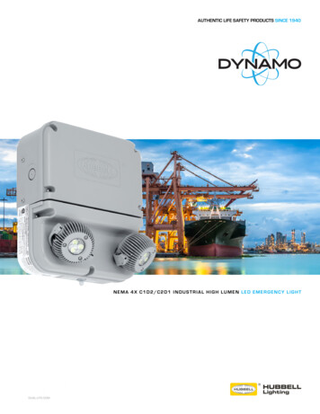
Obstruction Lights—LED General UseL810 GeNEral USELED OBSTRUCTION LIGHTCertified to: FAA AC NO: 150/5345-43FCompliant to: Canadian Aviation RegulationCAR 621.9 (Transport Canada) ICAO (Annex 14)Low intensity Type A (10cd)Low intensity Type B (32cd)VER IF I E DOrdering Information †Features/Benefits Available as a single or dual unitVoltage vailable in 12VDC, 24VDC, 48VDC, 120VAC, andA240VAC versions (50 or 60Hz)120VACOWLFSR/120OWLFDR/120240VACOWLFSR/240 ‡OWLFDR/240 ‡Earth grounding provisions provided12VDCOWLFSR/12OWLFDR/12 nique optically designed lens to enhance LEDUoperation and provide 360 FDR/24 eather/corrosion resistant lamp assemblyWand housingCatalog Numbering SYSTEM elf-contained wiring compartment eliminatesSadditional boxesO ObstructionS Single or D DualW Non Hazardous LocationR Red Threaded 1" and 3/4" bottom hub for mountingL Light Emitting Diode (LED)120, 240 Voltage AC an be operated steady or flashedC(controller not supplied)F FAA Type L81012, 24, 48 Voltage DCResistant to shock and vibration NEMA 4X rated and IP66† Standard product meets both 32cd and 10cd requirements‡ 240VAC lights are also available in 50cd and 10cd only. For 50cd only, remove “F”from catalog number and add “ICAO50CD” to end. For 10cd only remove “F” fromcatalog number and add “ICAO10CD to end. Ex. OWLSR/240 ICAO50CDApplication he Cooper Crouse-Hinds LED ObstructionTlight is a type FAA L810 red obstruction light.Designed for steady burning, this fixture is usedto mark any obstacle that may present hazardsto aircraft navigation.Specifications Dual FixtureState-of-the-art high-flux LED technology Single Fixture perating Temperature: -67 F to 131 FO(-55 C to 55 C)Finish Cast aluminum housing Stainless steel hardware20
Obstruction Lights—LED General UsePHOTOMETRIC DATAMECHANICAL DIMENSIONSL810 Isotropic Intensity Chart60.0-80.0Lens 0-20.01050(9.75") 247.7mmREFVertical 79") 147mmREF-1590 135 180 225 270 315Horizontal Angle (deg)(15.54") 394.6mmREFWeights & MeasurementsPart NumberApprox. Shipping WeightContainer DimensionsSingle Unit7.1 lbs16" x 9" x 8"Dual Unit16.1 lbs22" x 17" x 9"PFElectrical SpecificationsOPERATING VOLTAGEVAWATTS (W)MinTypMaxMinTypMaxAMPS120VAC UNITS.346.5921201321015180.120240VAC UNITS (60Hz).17721982402641115180.120240VAC UNITS (50Hz)––198240264121417–12VDC UNITS (STANDARD)––1012142025292.00024VDC UNITS––2124271722290.92048VDC UNITS––4348531114160.27521
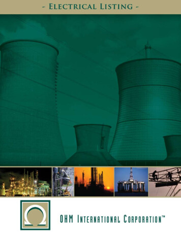
Obstruction Lights—LED Class I, Division 2L810 Class I, division 2LED OBSTRUCTION LIGHTSuitable for Use in Hazardous AreasETL Listed in compliance with UL1598 and UL844for use in Class I, Div 2 Hazardous LocationsCertified to: FAA AC NO: 150/5345-43FCompliant to: ICAO (Annex 14)Type A or Type BCanadian Aviation RegulationCAR 621.9 (Transport Canada)VER IF I E DOrdering InformationFeatures/Benefits Available as a single or dual unitVoltageSingle FixtureDual FixtureColor uitable for all Class I, Div 2, Groups A, B, C, DShazardous environments, T4 240OX2LFDR/240Red nique optically designed lens to enhance LEDUoperation and provide 360 visibilityCatalog Numbering SYSTEMUp to 100,000 hours of service life eather/corrosion resistant lamp assemblyWand housingO elf-contained wiring compartment eliminatesSadditional boxesThreaded 1" and 3/4" bottom hub for mounting an be operated steady or flashedC(controller not supplied) Resistant to shock and vibration NEMA 4X rated and IP66 Available in 120VAC and 240VAC (50 or 60Hz) Energy efficient LED technologyX2 H azardous LocationClass I, Div 2R RedL Light EmittingDiode (LED)12, 24, 48 Voltage DCF FAA Type L810 Cast a
Obstruction Lighting Devices as Tough as Your Environment For more than a century, companies have come to rely on Cooper Crouse-Hinds for value they can trust to grow their business. By integrating a comprehensive line of electrical products with expert support, industry insights and