Transcription
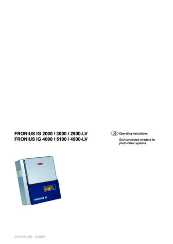
FRONIUS IG 2000 / 3000 / 2500-LVFRONIUS IG 4000 / 5100 / 4500-LV42,0410,1089022008US Operating instructionsGrid-connected inverters forphotovoltaic systems
Dear ReaderIntroductionThank you for choosing Fronius - and congratulations on your new, technically highgrade Fronius product! This instruction manual will help you get to know your newmachine. Read the manual carefully and you will soon be familiar with all the manygreat features of your new Fronius product. This really is the best way to get the mostout of all the advantages that your machine has to offer.Please also take special note of the safety rules - and observe them! In this way, youwill help to ensure more safety at your product location. And of course, if you treat yourproduct carefully, this definitely helps to prolong its enduring quality and reliability - thingswhich are both essential prerequisites for getting outstanding results.ud fr st et 00493012004
Safety rulesDANGER!WARNING!CAUTION!“DANGER!” indicates an imminently hazardous situation which, if notavoided, will result in death or serious injury. This signal word must belimited to the most extreme situations. This signal word is not used forhazards relating to property damage unless there is also a risk of personalinjury appropriate to this level.“WARNING!” indicates a potentially hazardous situation which, if notavoided, could result in death or serious injury. This signal word is not usedfor hazards relating to property damage unless there is also a risk of personal injury appropriate to this level.“CAUTION!” indicates a potentially hazardous situation which, if not avoided, may result in minor or moderate injury. It may also be used to drawattention to unsafe practices that may cause damage to property.NOTE!“NOTE!” indicates a situation which implies a risk of impaired results anddamage to the equipment.Important!“Important!” indicates practical hints and other particularly useful information. It is not a signal word for a harmful or dangerous situation.Whenever you see any of the symbols shown above, pay close attention tothe contents of the manual!General RemarksThis equipment has been manufactured in accordance with the state of theart and general safety-engineering principles. Nevertheless, incorrect operation or misuse may still endanger- the life and well-being of the operator or of third parties,- the equipment and other tangible assets belonging to the owner/operator,- working efficiently with the equipment.All persons involved in any way with starting up, servicing and maintainingthe equipment must- be suitably qualified- have good knowledge of dealing with electrical installations and- read this instruction manual thoroughly and follow the instructions to theletter.The instruction manual must be kept at the machine location at all times. Inaddition to the instruction manual, it is important to comply with both thegenerally applicable and local accident prevention and environmental protection regulations.Iud fr se sv 00923022005
General Remarks(continued)All the safety instructions and warning signs on the machine itself:- must be kept in a legible condition- must not be damaged- must not be removed- must not be covered, pasted or painted overFor information about where the safety instructions and warning signs arelocated on the machine, please refer to the section of your machine’s instruction manual headed “General Remarks”.Any malfunctions which might impair machine safety must be remediedimmediately before the machine is switched on.Your safety is at stake!Utilisation forIntended PurposeOnlyThe machine may only be used for jobs as defined by the “intended purpose”.Utilisation for any other purpose, or in any other manner, shall be deemed"not in accordance with the intended purpose". The manufacturer shall notbe liable for any damage resulting from such improper use.Utilisation in accordance with the “intended purpose” also comprises- thorough reading of and compliance with all the instructions, safetyinstructions and warnings given in this manual- performing all stipulated inspection and servicing work- installation in accordance with the instruction manualWhere appropriate, the following guidelines should also be applied:- regulations of the power supply company for input to the grid- information provided by the manufacturer of the solar modulesOperation or storage of the machine outside the stipulated range is deemed“not in accordance with the intended use”. The manufacturer shall not beliable for any damage resulting therefrom.AmbientConditionsPlease refer to the technical data in your instruction manual for accurateinformation about the permissible ambient conditions.Qualified StaffThe servicing information provided in this instruction manual is only intendedfor qualified staff. An electric shock can be fatal. Please do not carry out anyactivities other than those referred to in the documentation. This also applieseven if you are suitably qualified.All cables and other leads must be firmly attached, undamaged, properlyinsulated and adequately dimensioned. Have loose connections, scorched,damaged or under-dimensioned cables and wires repaired immediately byan authorised specialist company.ud fr se sv 00923022005II
Qualified Staff(continued)Maintenance and repair may only be carried out by an authorised specialistcompany.There is no guarantee in the case of parts sourced from other suppliers thatthese parts have been designed and manufactured to cope with the stressesand safety requirements that will be placed on them. Use only original spareparts (this also applies to standard parts).Do not carry out any alterations, installations or modifications to the machinewithout first getting the manufacturer’s permission.Replace immediately any components that are not in perfect condition.Safety Precautions at the Machine LocationEnsure when installing machines with cooling-air vents that the cooling air can flow freelythrough the air vents without obstruction. Only operate the machine with the degree ofprotection specified on the rating plate.EMC PrecautionsCare must be taken during installation to ensure that there is no occurrenceof electromagnetic interference with electrical and electronic equipment.Electrical InstallationsElectrical installations may only be executed in accordance with the relevantnational and regional standards and specifications.ESD ProtectiveMeasuresDanger of damage to electronic components due to electrostatic discharge.Take appropriate protective measures when replacing and installing thecomponents.Safety Precautions in NormalOperationOnly operate the machine if all its protective features are fully functional. Ifany of the protective features are not fully functional, there is a danger to:- the life and well-being of the operator or other persons- the equipment and other tangible assets belonging to the owner/operator- working efficiently with the equipment.Have any safety features that are not fully functional repaired by an authorised specialist company before switching the machine on again.Never bypass or disable safety features.IIIud fr se sv 00923022005
Safety markingsEquipment with the CE mark fulfils the basic requirements of the GuidelineGoverning Low-Voltage and Electromagnetic Compatibility. (More detailedinformation about this may be found in the Annex or in the section of yourdocumentation headed “Technical Data”.)DisposalDo not dispose of this device with normal domestic waste!To comply with the European Directive 2002/96/EC on Waste Electrical andElectronic Equipment and its implementation as national law, electricalequipment that has reached the end of its life must be collected separatelyand returned to an approved recycling facility Any device that you no longerrequire must be returned to our agent, or find out about the approved collection and recycling facilities in your area.Ignoring this European Directive may have potentially adverse affects on theenvironment and your health!Data securityThe user is responsible for backing up data relating to changes made tofactory settings. The manufacturer will not accept liability if personal settingsare deleted.CopyrightCopyright to this instruction manual remains the property of themanufacturer.The text and illustrations are all technically correct at the time of going toprint. The right to make modifications is reserved. The contents of theinstruction manual shall not provide the basis for any claims whatever on thepart of the purchaser. We should be most grateful for your comments if youhave any suggestions for improvement, or can point out to us any mistakeswhich you may have found in the manual.ud fr se sv 00923022005IV
Table of ContentsIMPORTANT SAFETY INSTRUCTIONS - SAVE THESE INSTRUCTIONS . 4General . 4Housing . 4Galvanic isolation . 5Monitoring the grid . 5Repair . 5Solar modules . 5Grid connection . 6Standards and Regulations. 6Product listings and compliance . 6How a photovoltaic system works . 7General information . 7Your roof is your power generator . 7Electricity is converted under the roof . 7Operation manual . 8The FRONIUS IG Unit in the PV System. 8General information . 8Converting DC into AC current . 8Fully automatic operation management . 9Voltage transformation and galvanic isolation. 9Monitoring the grid . 9Information for Field adjustable trip points . 10Display function and data communication . 10Your advantage . 10Product description.11The FRONIUS IG Unit .11How it functions .11Startup phase .11Overview for housing . 13LED for operating status . 15LED for GFDI status . 16Operating scheme . 17The Display. 17General information . 17Keys and symbols. 17Symbols . 171
Display Navigation . 18Display illumination . 18Menu level . 19Select display mode . 19Scrolling between display functions . 20Display Modes . 20Display mode outline . 20Display symbol key . 21Display mode "Now" . 22Display mode "Day / Year / Total" . 24The Setup Menu . 28List of menu items . 28Display mode "Setup" . 29Enter the setup menu . 29Scroll among menu items . 29Setting the menu items . 30Additional information . 39Upgrading the system . 39Forced ventilation . 40Installation manual . 41Installation . 42Installation instructions . 42Safety . 42General information . 42Choosing the location general . 43Choosing the location . 43Preparing the wall mounting . 44Connection . 45Safety . 45General . 45Connection to the Solar Modules and to the Utility Grid . 45Solar modules . 45Grid connection . 46Schemes with more than one inverter . 48Connection . 49Connect DC . 52Connect AC . 53Start up Operation . 53Configuring your Inverter . 53Factory pre-set configuration . 53Your personal configuration . 542
Ground fault indication . 54General . 54LocalNet . 55System upgrading / plug-in card system . 55Datalogger . 55COM Card . 55Insert plug-in cards . 56Configuration . 57Example . 57Status diagnosis and repair . 58Service-Codes Displayed . 58Service display. 58Normal operation service codes . 58System failure . 59FRONIUS IG with several power stage sets . 59Class 1 . 60Class 2 . 61Class 3 . 62Class 4 . 63Class 5 . 65Customer service . 66Annex . 67Technical Data . 67General . 67Field adjustable trip points . 68General . 69Field adjustable trip points . 70FRONIUS USA limited 10-Year Warranty . 71FRONIUS IG Solar Inverter Models:FRONIUS IG 2000 / 3000 / 2500 LV / 4000 / 5100 / 4500-LV . 71Policy and procedure for warranty returns and repairs . 71Disposal of obsolete equipment . 72Recycling . 72Declarations of conformityFronius Worldwide3
IMPORTANT SAFETY INSTRUCTIONS - SAVE THESE INSTRUCTIONSGeneralWARNING! Incorrect operation and work performed incorrectlycan cause serious injury & damage! Only qualified staff areauthorized to install your FRONIUS IG and only within the scope of the respective technical regulations. Do not start operation or carry out maintenance work before you have read thechapter “Safety Regulations“!This manual contains important instructions for the FRONIUS IG2000, 3000, 2500-LV, 4000, 5100, 4500-LV that shall be followedduring installation and maintenance of the inverters.WARNING! These servicing instructions are for use by qualifiedpersonnel only. To reduce the risk of electric shock, do notperform any servicing other than that specified in the operatinginstructions unless you are qualified to do so.Electrical installations must be made in accordance with the NationalElectrical Code, ANSI/NFPA 70, and any other codes and regulationsapplicable to the installation site.To reduce the risk of fire, do not connect multiwire branch circuits toan AC load center (circuit breaker panel).HousingOnly qualified installers are authorized to open the connection area.Do not open the connection area when the inverter is under voltage.Only Fronius-trained service staff may open the upper portion (powerstage) of the inverter, and only when it is not under voltage.4
GalvanicisolationThe design and function of the FRONIUS IG unit offers a maximumlevel of safety, both during installation as well as in operation. A complete galvanic isolation between the DC and AC sides is one suchsafety feature.The FRONIUS IG provides galvanic isolation and grid monitoring.The passive and active measures for the protection of persons andequipment help ensure safe installation and operation.Monitoringthe gridWhenever conditions in the electric grid are inconsistent with standard conditions (for example grid switch-off, interruption, etc.), yourFRONIUS IG unit will immediately stop operating and interrupt thesupply of power into the grid.Your FRONIUS IG unit determines the grid’s status by:- monitoring voltage- monitoring frequency- monitoring islanding conditionsThis scheme prevents dangerous voltages at the AC lines and constitutes an essential contribution towards avoiding hazards for themaintenance staff.RepairOnly FRONIUS service staff are authorized to carry out repairs to theFRONIUS IG unit.Solar modulesBefore connecting the solar modules, you must check whether thevoltage parameters specified in the manufacturer’s data correspondwith the actual parameters.When checking the voltage reading, please take into account thatsolar modules supply a higher open circuit voltage when temperatures are low and sunlight level remains unchanged.The data sheet of the solar module will tell you the temperature factors applicable for ascertaining the theoretical open-circuit voltage at14 F (-10 C).If the solar modules exceed an open-circuit voltage of 500 V, regardless of temperature the FRONIUS IG unit might be damaged and allwarranty rights will be voided.5
Solar modules(continued)The FRONIUS IG includes a ground fault detector interruptor (GFDI)according to UL 1741. This device measures the ground current ofthe PV array and prevents the inverter from feeding the grid in caseof a ground fault.Grid connectionOnly appropriately licensed contractors are authorized to connectyour FRONIUS IG to the grid. Consult your local authorities for specific requirements.Before connecting the FRONIUS IG to the grid, permission for theconnection must be granted by the utility company.Standardsand RegulationsYour FRONIUS IG unit complies with the requirements for "Inverters,converters and controllers for use in independent power systems"UL1741-2005 and IEEE 1547 standards. The ground-fault detectionand interruption is in compliance with NEC 690 building code requirements.Product listings andcomplianceThe respective conformity declarations can be found in the appendixto these operating instructions.6
How a photovoltaic system worksstringmod. 2mod. nmod. 1--mod. 2string 3string 2string 1mod. 1 total string voltagemodule 1module 2 module 3Power output and voltage are increased by combining a number ofsolar cells. If solar modules are connected in series like on a string,both the output power as well as the voltage will increase.voltageYour roof isyour powergeneratorvoltageThe energy from worldwide sunlight amounts to a total of about1,540,000,000,000,000,000 kWh/year (1,540 Peta kWh/year). This is15,000 times as much as the electricity consumption worldwide. Wecongratulate you on your decision to actively use world’s biggestenergy resource. The word "photovoltaic" comes from the drivingforce behind this technology, which is light. When light strikes photovoltaic cells, a voltage and current is created.voltageGeneral informationmod. ntotal array current current string 1 2, . nIn a parallel connection of several such strings the output power andthe output current will increase, while the voltage will remain unchanged (see right picture). The combination of all solar modules connected in series and parallel is called a solar array.Electricity isconvertedunder theroofThe direct current generated in the solar modules can only be fedinto the grid or used in your home after having been transformed byan inverter.This is the basic purpose of your FRONIUS IG unit.7
Operation manualThe FRONIUS IG Unit in the PV SystemGeneral informationThe FRONIUS IG is the latest generation of solar inverter. It is thehighly complex link between solar modules and the grid.As such it is responsible for a number of high-level tasks. The following diagram gives a graphical overview as to where the FRONIUSIG is placed in the PV system.FRONIUS IGMain ACLoadCenterPV arrayConvertingDC into ACcurrentEnergymeterThe FRONIUS IG unit transforms the direct current generated by thesolar modules into alternating current. This alternating current is fedinto your home system or into the public grid and synchronized withthe voltage that is used there. The FRONIUS IG has been designedexclusively for use in grid connected photovoltaic systems. It cannotgenerate electric power independent from the grid.8
Fully automatic operationmanagementThe FRONIUS IG is fully automatic. Starting at sunrise, as soon asthe solar modules generate enough power, the automatic control unitstarts monitoring voltage and frequency. As soon as there is a sufficient level of insolation, your solar inverter starts feeding energy tothe grid. A few Watts of solar power output are sufficient to achievethis.The control system of the FRONIUS IG unit ensures that the maximum possible power output is drawn from the solar modules at alltimes.This function is called MPPT (Maximum Power Point Tracking). Itoperates with extremely high precision. As dusk starts and there isno longer sufficient energy available to feed power into the grid, theFRONIUS IG unit shuts down the grid connection completely andstops operating. All settings and data recorded are saved.Voltage transformationand galvanicisolationThe FRONIUS IG has been designed for use with solar modules of awide range of input voltages. This allows the use of the greatestvariety of types of solar modules. Important notice: the parametersindicated for maximum DC voltage (total voltage of the solar modulesconnected) must at no time be exceeded!By its design and operation, the FRONIUS IG offers maximum safetyduring installation as well as in operation.The FRONIUS IG is equipped with an HF-transformer (HF highfrequency) that ensures galvanic isolation between the DC side andthe grid. In addition, the HF principle results in a drastic reduction ofthe transformer’s size, which means that it requires less space andhas considerably less weight. The FRONIUS IG unit achieves a highdegree of efficiency due to its innovative circuit schemes.Monitoringthe gridThe FRONIUS IG unit monitors the grid. This responsibility comprises all measures necessary for the protection of persons and machines in case of a power blackout or other grid loss.The FRONIUS IG unit is programmed to stop operation immediatelyand stop supplying power whenever conditions in the grid deviatefrom standard conditions (for example, when power is switched off orin case of any other kind of interruption).9
Monitoringthe grid(continued)There are several ways the FRONIUS IG unit can identify a gridcutoff, by monitoring:- voltage- frequency- islanding conditionsInformationfor Fieldadjustabletrip pointsThe FRONIUS IG unit is provided with field adjustable trip points. Forfurther information please contact Fronius technical su
FRONIUS IG 2000 / 3000 / 2500-LV FRONIUS IG 4000 / 5100 / 4500-LV 42,0410,1089 022008 US Operating instr
