Transcription
IEEE 1547IEEE 1547: Standard for Interconnection andInteroperability of Distributed EnergyResources with Associated Electric PowerSystems 7 revision/1547revision index.html
Index What is IEEE 1547?Ride throughVoltage regulationPower QualityOverview of interoperability, island systems,and testing
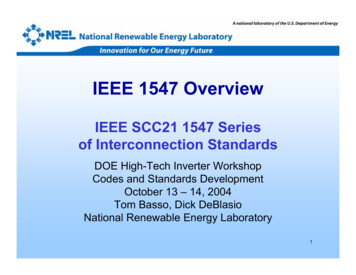
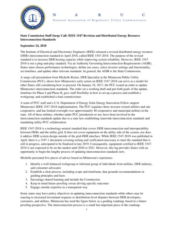
Challenges of Grid ModernizationTraditionalElectric Grid Modern ElectricityChoices Utility s3EV’sLoad as aresource3Power parkRemoteIndustrial DG LoadsFuelCellsSmartSubstationCombined Heat and Power
P1547 Revision: Draft Standard for Interconnection and Interoperability ofDistributed Energy Resources with Associated Electric Power SystemsInterfaces.Scope: This standard establishes criteria and requirements forinterconnection of distributed energy resources (DER) withelectric power systems (EPS), and associated interfaces.Note: Interfaces defined in IEEE 2030: “a logical interconnection from one entity toanother that supports one or more data flows implemented with one or more data links.Purpose: This document provides a uniform standard for theinterconnection and interoperability of distributed energyresources (DER) with electric power systems (EPS). It providesrequirements relevant to the interconnection andinteroperability performance, operation, and testing, and,safety, maintenance and security considerations.
5
1547: Interconnection Is The FocusIEEE Std 1547 covers:- INTERCONNECTION TECHNICAL SPECIFICATIONS & REQUIREMENTS- INTERCONNECTION TEST SPECIFICATIONS & Note: P1547 full revision started in(DER)year 2015 is also bility and interfacesSystem(EPS)
A Technical Standard – FunctionalRequirements For the interconnection itself the interconnection test Technology neutral, e.g., does not specify particular IEEE 1547IS:IEEE 1547Is NOT:IEEE 1547.1 is:Test Procedures forConformance to1547equipment nor type A single (whole) document of mandatory,uniform, universal, requirements that apply atthe PCC or Point of DER Connection. Should be sufficient for most installations. a design handbook an application guide an interconnection agreement prescriptive, e.g., does not addressDR self-protection, nor planning,designing, operating, or maintainingthe Area EPS.7
IEEE Std 1547a – Amendment 1, May 2014(Amendment 1: revisions to 4.1.1, 4.2.3, and 4.2.4)4.1.1 Voltage Regulation DER allowed to change its output of active and reactive power.4.2.3 (Response to abnormal grid ) Voltage . DER allowed to “ride through” abnormalities of grid voltage; grid and DER operators can mutually agree to other voltage trip and clearingtime settings4.2.4 (Response to abnormal grid ) Frequency DER allowed to provide modulated power output as a function of frequency grid and DER operators can mutually agree to other frequency trip andclearing time settings8
PCC vs Point of DER Connection
Point of EvaluationRequirements shall be met at the Point of Common Coupling(PCC) for all Local EPS having an aggregate DER nameplate rating of 500 kW orgreater, and having an average load demand of equal or less than 10%of the DER nameplate rating.In all other situations, the applicable point for meetingperformance requirements shall be the Point of DERconnection
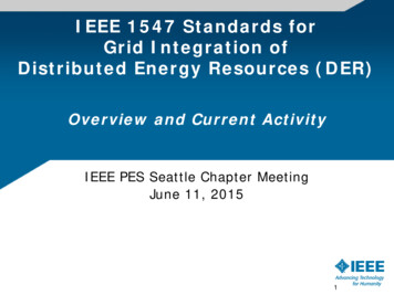
P1547 New Requirements forRide Through (Work In Progress) Three Categories of DER Operational Responses to Support the Grid -- Based onLocal and Farther Reaching Grid Requirements and DER
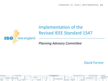
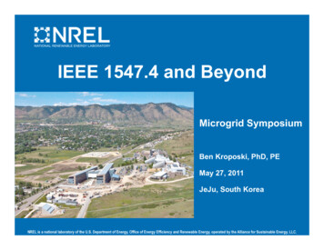
P1547 Example New Requirementsfor voltage Ride Through (work in progress)Category I(based on German requirements for sync. gen.)1.30may ride-through 0.16 sor may trip1.2021smayride-throughPermissive Operation1.10shall trip1.20 p.u.13 sNERCPRC-024-211.10 p.u.Continuous Operation1.00Voltage (p.u.)0.900.88 p.u.0.88 p.u.Mandatory Operation0.800.70Permissive Operation0.601GermanMV Code forsyncr. DERmay ride-through or may trip2s21 srange of adustability0.16 s0.50may ride-throughor may trip0.40default value0.50 p.u.0.16 s0.300.16 sLegendshall trip zonesmay ride-through ormay trip zones2s2shall ride-through zonesand operating regionsdescribing performance0.200.100.00 p.u.shall trip0.00 p.u.0.000.010.1110Time (s)1001000
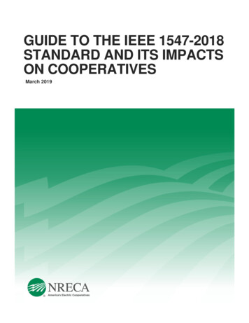
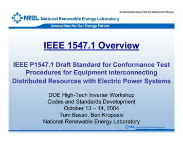
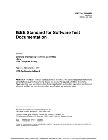
P1547 Example New Requirementsfor frequency Ride Through (work in progress)Category I, II, and III(harmonized)66.0 Hz66.0 Hz63.0may ride-throughor may trip62.5shall trip62.0 Hz62.00.16 s1 000 s2299 s61.5Mandatory Operation180 s61.060.6 HzFrequency (Hz)60.561.0 Hz1 may ride-through1 000 sor may trip60.0Continuous Operation(V/f 1.1)59.559.059.0 HzLegend58.5range of adustabilityMandatory Operation58.0default value57.5may ride-through ormay trip zones180 s299 sshall ride-through zonesand operating regionsdescribing performanceshall trip zones1 000 s157.0 Hz57.0may ride-throughor may trip56.5may ride-through or may trip0.16 s1 000 s2shall trip56.00.010.150.0 Hz110Time (s)1410050.0 Hz1000
Distribution grid impacts that need to be carefullyreviewed by the utility protection engineer !! Distribution Feeder Fault Detection Anti-islanding protection
P1547 voltage regulation(Work In Progress)Two performance categories are defined forDERs with voltage regulation capabilities:a)Category A covers minimum performance capabilities needed forArea EPS voltage regulation and are reasonably attainable by all state-of-theart DER technologiesb)Category B covers all requirements within Category A and specifiesadditional requirements to mitigate voltage variations due to resourcevariability
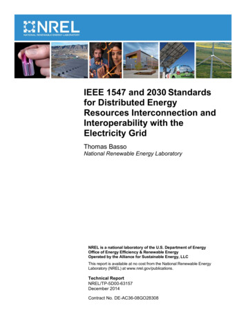
P1547 Example New ReactivePower Requirements (Work In Progress)The DER shall be capable of injecting reactive power (over-excited) and absorbing reactivepower (under-excited) equal to the minimum reactive power (kVar) corresponding to thevalue given in Table TBD at all active power output greater than or equal to 20% ofnameplate active power rating (kW) or the minimum steady-state power capability of theDER, whichever is greater. As an additional requirement, Category B DER shall providesaid capability at all active power levels subject to the restriction that the ratio of theaverage of absolute value of DER reactive power over the preceding 24 hour perioddivided by the average of absolute value of DER apparent power over the preceding 24hour period is less than 0.44.
Voltage and Reactive Power ControlThe DER shall provide the capabilities of the following modes ofreactive power control functions:1. Adjustable Constant Power factor mode – The capability ismandatory for categories A and B2. Voltage-reactive power (Volt-var) mode – The capability ismandatory for categories A and B3. Active power-reactive power mode (watt-var) – The capabilityis optional for category A and mandatory for categories B4. Reactive power mode – The capability is mandatory forcategories A and B
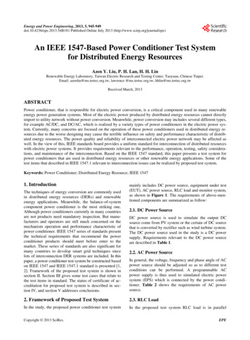
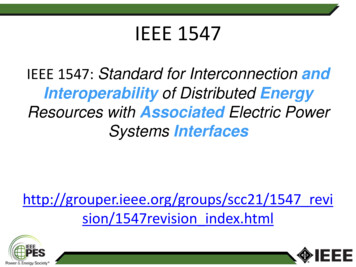
(V1,Q1)Injecting (over-excited)0Absorbing (under-excited)Reactive Power (% of Stated Capability)P1547 Example New Reactive Power Requirements(Work In Progress)Dead BandVoltage (p.u.)VRef (V3,Q3)VLV1(V2,Q2)VL: Voltage Lower Limit for DER Continuous operationVH: Voltage Upper Limit for DER Continuous operationV4(V4,Q4)VH
20The Volt/VAR characteristics curve is adjustableVolt-var ParametersDefinitionsDefault Values forCat A DERDefault Values forCat B DERVRefReference voltageNominal Voltage(VN)Nominal Voltage (VN)V2Dead band lower Voltage LimitNominal Voltage(VN)VRef – 0.02 VNQ2Reactive power injection orabsorption at voltage V200V3Dead band upper Voltage LimitNominal Voltage(VN)VRef 0.02 VNQ3Reactive power injection orabsorption at voltage V300V1Voltage at which DER shall injectQ1 reactive power0.9 VNVRef – 0.08 VNQ1Reactive power injection atvoltage V125% of NameplatekVA100% of stated reactivecapabilityV4Voltage at which DER shall absorbQ4 reactive power1.1 puQ4Reactive power absorption atvoltage V425% of NameplatekVA100% of stated reactivecapability10 sec60sOpen Loop Response TimeMode/setting timeTime to 95% of the reactive powerchange in response to the changein voltageMaximum Time by which mode orsetting changes are to be madeeffectiveVRef 0.08 VNAdjustable RangeMinimumMaximum0.95 VN1.05 VNCat A: VrefCat B; VRef – 0.03 VNVRef0100% of stated reactivecapabilityCat A: VrefVRefc00.82 of VN0Cat B: VRef 0.03 VN100% of stated reactivecapabilityV2 c-0.02 VN100% of stated reactivecapability1.18 VNV3 c 0.02 VN0100% of stated reactivecapability b5 sec1s90s60s5s5 min
Active Power – Reactive Power(Watt-Var or P - Q) ModeWhen in this mode, the DER shall actively control the reactivepower output as a function of the real power output following atarget real power – reactive power (Watt-Var or P-Q) jection/Capacitive/ OverExcited(P’1,Q’1)P’3(P’2,Q’2)(P1, Q1)(0,0)-0.2(P2, Q2)P30.2Absorption/Inductive/UnderExcited(P3, Q3)QminabsP/PRated1
P1547 Example New VoltageRegulation Requirements (Work In Progress)Voltage-Real Power (Volt-Watt) ModeWhen in this mode, the DER shall actively control the real output power as afunction of the system voltage following a target voltage – active power (voltwatt) characteristic ceVoltageV3 (% of VN)P3V4V1V2V3Voltage(% of VN)V4V1V2P3ESS going intoCharge mode
Transition from abnormal tonormal voltage conditionsThe requirements of the voltage regulationclause (4.1) apply to normal voltage range whenthe voltage is between 0.88 and 1.1 times thenominal voltage (VN). The voltage conditionsoutside of this range are defined to beabnormal. The DER shall return to its predisturbance operating mode after the systemvoltage returns to its normal range.
Grid impacts that need to be carefully reviewedby the utility engineer !! Anti-islanding protection Reactive Power coordination amongst existingDERs and utility assets i. e. capacitor banks, etc. Prioritizing the voltage regulation schemes
25Are voltage regulation and ride-throughrequirements proposed to be mandatory? The ride-through capability and performanceis proposed to be mandatory. The voltage regulation capability is proposedto be mandatory but the performance isproposed to be at the utility’s discretion (TheDER will provide this capability and the utilitywill decide to enable/disable it and choose theproper operating modes).
Rapid voltage changes (RVC) Rapid voltage changes are considered to be changes in fundamentalfrequency voltage less than one second . The DER shall not cause theΔV/V voltage variations to go outside the limits specified in table X. (Ref.IEEE 1453)Number of Changes (moving window)ΔV/V %n 4 per day6n 2 per hour and 4 per day42 n 10 per hour3For the one-day moving window of Table X, each new RVC event shall be assessed separately using a sliding one-day window. The new RVC event and all RVCevents that occurred in the preceding 24 hours shall be counted together to determine if the new RVC event exceeds the maximum number of rapid voltage changes allowedin one day. For the one-hour moving window of Table X, each new RVC event shall be assessed separately using a sliding one-hour window.The new RVC event and all RVC events that occurred in the preceding 60 minutes shall be counted together to determine if the new RVC event exceeds the maximumnumber of rapid voltage changes allowed in one hour.
FlickerFlicker- Flicker is the subjective impression of fluctuatingluminance caused by voltage fluctuations. Assessmentmethods for flicker are defined in IEC 61000-3-7. Pst99% (99th percentile value) shall not be greater than0.9. If not specified differently, the Pst evaluation timeis 10 minutes. Plt99% (99th percentile value) shall not be greater than0.7. If not specified differently, the Plt evaluation time is2 hours.
P1547 Example New Power QualityRequirements (Work in progress)Harmonics: When the DER is serving balanced linear loads, harmonic current injection into the AreaEPS at the Point of DER interconnection shall not exceed the limits stated below.The harmonic current injections shall be exclusive of any harmonic currents due toharmonic voltage distortion present in the Area EPS without the DER connected.
P1547 Example New Power QualityRequirements (Work in progress)Any aggregated interharmonic current distortionbetween h /-5Hz shall be limited to the associatedharmonic order h limit in Tables 3 and 4. Anyaggregated interharmonics current distortionbetween h 5Hz and (h 1)-5Hz shall be limited tothe lesser magnitude limit of h and h 1 harmonicorder.
P1547 Example New Power QualityRequirements (Work in progress)As an alternative, a self-excited DER, e.g., synchronous generator, shall be tested to meet the requirements of 4.3.3; either after installation orwhile powering a balanced resistive load and isolated from any other sources. The voltage harmonics while powering a resistive load at 100%of the machine kVA rating shall not exceed the levels in Tables 5 and 6 for odd and even harmonics, respectively. Voltage harmonics shall bemeasured line to line for 3-phase/3 wire systems, and line to neutral for 3-phase/4-wire systems.Table 5—Maximum odd harmonic voltage distortion in percent of rated voltageIndividualoddharmonicorder hh 1111 h 1717 h 2323 h 3535 hTotal rateddistortionup to the h 50harmonic(TRD)Percent (%)4.02.01.50.60.35.0Table 6- Maximum even harmonic voltage distortion in percent of rated voltageIndividual evenh 2harmonic order hPercent (%)1.0h 4h 68 h2.03.0Associated range specified on theprevious slide
P1547 Example New Power Quality RequirementsOver Voltage Contribution-Temporary Over-voltage (TOV)Limitation of over-voltage over one fundamental frequency period The DER shall not contribute to instantaneous or RMS over voltages with the followinglimits: The DER shall not cause the RMS Line-Ground voltage on any portion of the Area EPSt
IEEE 1547 IS: IEEE 1547 Is NOT: a design handbook an application guide an interconnection agreement prescriptive, e.g., does not address DR self-protection, nor planning, designing, operating, or maintaining the Area EPS. IEEE 1547.1 is: Test Procedures for Conformance to1547