Transcription
IEEE 1547 and Small Photovoltaic‐Based Generation Case StudiesGerald Johns, P.E.TVA KentuckyComprehensive Services
IEEE 1547 IEEE StaStandardda d foro Interconnectingte co ect g Distributedst butedResources with Electric Systemsppto anyy and all distributed resources Applicablewith aggregate capacity of 10 MVA and less. Primarily targets radial primary and secondarydistribution systems. “It provides requirements relevant to theperformance,foperation,tit ti safetytesting,f tconsiderations, and maintenance of theinterconnection ”1interconnection.1. IEEE Std. 1547‐20032
IEEE 1547 and UL 1741 Testing andCComplianceli To comply with IEEE 1547 the interconnection system must:– Exhibit a fixed 5‐minute5 minute time delay or adjustable delay of 5 minutes or less onstartup/restart– Respond to abnormal system conditions (voltage/frequency excursions) perIEEE 1547.– Not exceed steadysteady‐statestate harmonic and DC current content limitslimits.– Not produce objectionable flicker.– Detect and cease energization of the grid during unintentional islanding within2 seconds.– Pass synchronizationh i i andd interconnectiintegrityii testingi (EMI(andd surgewithstand). UL 1741 listing indicates compliance with IEEE 1547 as far asmanufacturer’s design and production testing is concerned.UL 1741 listing has no bearing on the installed interconnectionevaluation, commissioning test and periodic interconnection testsrequired by IEEE 1547.3
Basis for Commissioning Test from IEEE 1547 IEEE 1547 requires a visual inspection to verifygrounding coordination compliance and presence ofisolation device (when required by utility). Commissioning tests to include:– Isolation device operability.– Cease to energize functionality test on each phaseindividually (refrain from unintentional islanding)islanding).Verification of maximum response time and specified timedelay before reconnect.– Any of the design and/or production tests not alreadyperformed on the subject interconnection equipment (e.g.synchronization, response to abnormal voltage/frequencyconditions, etc. when discrete relayingy g is used).)4
Case 1: Excessive Steady‐State Voltage Due toCustomer Generation 37.44 kW in Rated Photovoltaic SystemyCapacityp y37.5 kVA, 7.2 kV to 120/240 1‐phase transformer at 2.5% ZMultiple DC to 240 VAC InvertersLittle to no load in office/shop building from which PVsystem fed. System complied with IEEE 1547.1547 Inverters are UL 1741listed.5
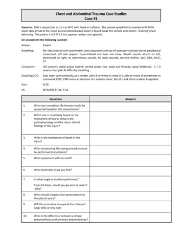
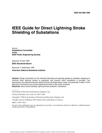
Example Utility‐InteractiveUtility Interactive Inverter6
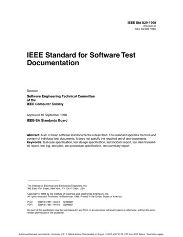
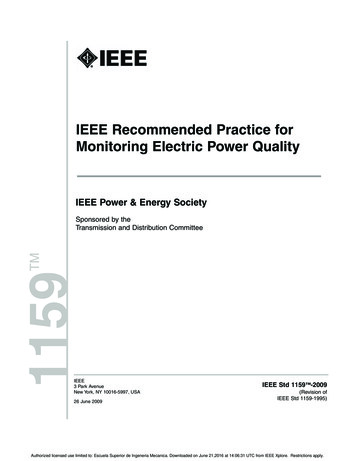
130 VAC Max at 35kW outputVoltageVoltageandlowerpowerdue tooutputdecreasedlowergenerationdue todecreased(overcast day)generation(overcast day)Fig. 1. Average/Maximum RMS Voltage and Average Total Power Output duringeach 5‐minute Interval7
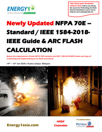
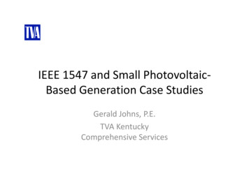
Fig. 2. Maximum/Average RMS Voltage during each 5‐minute Interval at OtherCustomer Site Just Upstream on Distribution Circuit8
Power Flow EquationsV1 Grid VoltageV2 Voltage at Inverter or Generator TerminalsMostlyy Resistive Systemy(low‐voltage systems)Mostlyy Reactive Systemy(high‐voltage systems)y, Voltageg at Inverter or Generator TerminalsIn Resistive Systems,Must be Greater than the Grid Voltage for Power Transfer TO theGrid!!9
248 voltslt (Utility(Utilitprimary voltage on 240volt base)0.033 W0.038 W258 volts248 (258 248) 35 kW0.07110
Recipe for Problems Virtually no load on the transformer secondary otherwise,most of the generated power would flow to the local load. Mild temperatures meaning reduced load on the utilitysystem resulting in slightly elevated baseline voltage andslightly higher solar panel output. PV system output near the kVA rating of the transformer.Voltage drop or voltage rise across the transformer higheras load/generation increases. Both the 260 volt RMS limit of the inverter and the126/252 volt RMS ANSI limit for the customer’s powerpsystem being exceeded. This is a problem for both theinverters and, potentially, the customer’s loads.Note that elevated voltage exceeded ANSI C84.1limits but did not constitute an abnormal voltagecondition as defined in IEEE 1547.11
Case 1 ‐ The Fix Replaced transformer that had no taps withtransformer with taps. Adjusted tap to lower secondary voltage.voltage Everybody happy (except for whoever had to pay forthe replacement transformer).12
Case 2: Use of Single‐PhaseInverters on a 3‐phasehSystem 208 volt threethree‐phasephase installation9.9 kW systemUsedd 1‐phasehmicroinvertersi iPerformance of the “3‐phase” interconnectionsystem questionable considering nocommunication between the 1‐phase units.13
Examples of Microinverters14
Common Workaround – PhaseMonitor Relayl15
Concerns with Using Phase Monitor Relay as aSolutionl i Only open phase and simultaneous disconnect of all threephases can be tested in typical commissioning test. Interconnection system includes components that have notbeen tested per IEEE 1547/UL 1741 in the factory, socommissioning test is to include testing response of thesystem to abnormal voltage/frequency conditions as well asother design/production tests. Design and production tests per IEEE 1547 requireequipment under test to be connected to a simulated utilityor signal injection test. Phase monitor relay performance may not satisfy IEEE 1547requirements.16
Other Solutions When inverters are installed using all threephases, a 3‐phase inverter is the best solution. Some manufacturers make accessories to linkindividual 1‐phase inverters together wheninstalled separately on 33‐phasephase systemssystems.These accessories should have been factorytested per IEEE 1547 and UL 1741 listed.listed17
IEEE 1547 and UL 1741 Testing and CliCompliance To comply with IEEE 1547 the interconnection system must: – Exhibit a fixed 5‐minute time delay or adjustable delay of 5 minutes or less on startup/restart – Respond to abnormal system conditions (voltage/frequency excursions) per IEEE 1547.