Transcription
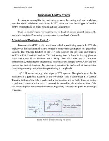
Microgrid System Design, Control, andModeling Challenges and SolutionsScott MansonSEL ES Technology Director SEL 2019
Agenda Example Projects Challenges Design Principles Reconnection Seamless Islanding Frequency Resilience Visualization Modelling What is Next?
Microgrid Examples
PowerMAX System Family TreePowerMAXTechnologyUtilitiesIndustrial PowerManagementCommercialMicrogridsGarrison MicrogridsMobile MicrogridsTypical CustomerSystem SizeBulk Electric PowerTransmission & GenerationOil & Gas, Heavy Industries 1 GWCommunities, Universities 10 MWFixed Military Installations 10 MWDisaster Relief, ForwardOperating Bases 0.5 MW 100 MW
POWERMAX Experience UncontestedOver 28,000 MW in Service Worldwide
How Others Use SEL Equipment forMicrogrids and DERsDo it yourselfSegmentSimple MicrogridsSimple DER PCC InterconnectionTechnologyRelaysRelays, RTACS Grid connect libraryProject FundinganyCustomer ExamplesEntergyApproximate ProjectCostApproximate ProjectSizeES officeIndependent power producers orUtilitiesUtilties ‐ XM (Columbia) Southerncompanies, Also Energy, New YorkPower Authority with Tesla batteries 5K 20K 10MW 100MWLocal OfficeLocal Office
PowerMAX for Utilities is Purpose Built forGigawatt Scale Generation
PowerMAX for IndustrialsDesigned for Heavy Industrial Customers
PowerMAX for Commercial CustomersAward Winning Controls for Complex Grids 10MW
Paris IslandPowerMAX Garrison Awarded to Ameresco via ESPC SEL PowerMAX being commissioned now“This is mostcomprehensiveseamlesslyintegrated DoDProject” - Ameresco
PowerMAX Mobile TechnologyInteroperable, Simple solution for 0.5MW Microgrids100 kW CAT30 kW Taylor30 kW GilletteLoadsLoads Red Cross60 kW TQGLoadsLoads FEMA Private DisasterReliefLoadsLoads ForwardOperating Base(FOBB)A4
Microgrid Challenges
Protective Relays Are MandatoryProtect Assets, Environment, and People
CR68SM32Not ResilientPower System Split Into Six Islands CollapsesIsland 451Island 6Island 3Island 5Frequency50.550Island 1Island 249.5495:256:257:25Time8:259:2510:25
ResilientSame Six Islands With Mature Microgrid me37:3138:3139:31
Frequency and Voltage are Resilience age (V)Frequency (Hz)6563Generation Shedding2Vt1 / Frequency (Hz)1.3 1.2Allowable OperationLoad Shedding5755Voltage (V)0.8 0.7
Engines Cannot Respond InstantaneouslyFrequency Decay Is Extraction ofKinetic Energy From Inertia6398Mechanical Power9762ElectricPower9661Note Lag in Response95Power(MW) 94Speed Frequency605993925891570510Time (s)1520
System InertiaSystem inertia (H) is J (kg m2) in terms of puJ (kg m2 )H secondsMVAFrequency decay is driven by power disparity and inertiadf Pdisparity dt2Hf
Load Composition Affects Frequency StabilityNoninertial Effects Electric loads increase transients Motors reduce transientsLoadsVSD Dominated70Frequency 60(Hz)50VSD and Induction Motor DominatedInduction Motor Dominated0204060Time (s)80100
Distributed Energy Resource (DER)Inverter-Based Generation HasLimited Overload CapacityQLong-Term Capacity LimitPQPRotating GeneratorsShort-TermCapacity LimitInverter-BasedGeneration
Load Balancing Must Happen Faster WithDER Inverter-Based GenerationPower,FrequencyRotating Generation PowerPowerInverter-Based PowerLoadFrequencyRotating Generation FrequencyInverter-Based FrequencyTime
Controller Must Understand DER CapabilityQ (MVAR)Q owableOperationalRegionP (MW)Operator-EnteredRegulation LimitsShort-TermCapacity LimitAllowableOperationalRegionP (MW)Long-Term Capacity Limit
Protection Must Adapt toChanging Fault Conditions Fault levelsDERt Grounding Directions2,000 ImpedancesRelay20,0002,00020,000I
DER Inverter Behavior IsSubject to Human PreferenceVInverter AFaultInverter BVttICurrentLimitItt
DER Inverter Behavior IsSubject to Human yPSoftwareEngineerMistakePSoftwareEngineerMistake
DER Inverter Phase-Locked Loops (PLLs)Fail When You Need Them Most DC–VdVq“Best Guess”FrequencyDQACIPWMABABC CMod. 60 Hz dtPLL4 kHzMeasureFrequencyMeasured Frequency
Design
Requirements for Technology1. Safe2. Reliable (resilient)3. Economical
Relays Are the Foundationof Microgrid Controls Multifunction protection Remote I/O Metering MIRRORED BITS high-speedcommunications Continuous self-diagnostics Power quality monitoring Synchrophasors Programmable logiccontroller function DC battery monitoring IEC 61850 compliance Front-panel interface thatreplaces all control switchesand pushbuttons
Relays Provide Distributed Protectionand Control for Small MicrogridsReconnectionLoad SheddingShort- and Open-Circuit ProtectionIEEE CompliancePower and Power Factor ControlProtectionGovernor and Exciter DispatchInverter DispatchLoad SharingVoltage and Frequency RegulationSCADADNP3PCCSEL-751PCC ratorDERRelaysSEL-751SEL-751SEL-751IEC 61850GOOSE
Centralized Controllers Communicate to RelaysVisualization and Diagnostic SystemSEL-3555RTACSEL POWERMAX Control SystemsEthernet Communications bstation Front-End Processor (FEP)Other IED
HMI SEL-2730MSEL-3555SEL-2730MPower Management System LANRelay-BasedControlsScale to AnySize PowerSystemSEL-2730MRTACSEL-3530Primary FEPSEL-2440 DPACRemote I/ORTACSEL-3530SEL-751A RelaysSubstationBackup FEPSEL-2730MRTAC
Use Relays for Small Grids;Use Relays and Controllers for Larger Grids120100Control80Functionality60in Relay(%)402001101001,00010,000 100,000 1,000,000 10,000,000Size of Islanded Grid (kW)Bulk ElectricCommunity MicrogridsIndustrial Microgrids Power Systems
POI orPCCIEEE 1547DERPCCDistributed Energy Resource(DER) is a catch-all name fortraditional and intermittentsourcesIEEE 1547IEEE 2030.8 – TestingPOIDERPOIPOIDERDERIEEE 2030.7 – Control
IEEE 2030.8-2018 RequiresThree Types of Mandatory Data CollectionWhich are in SEL relays!RequirementSEL Relay SolutionSequence of Events (SOE)SEREvent oscillographyEvent recordsContinuous data collectionSYNCHROWAVECentral
Reconnection
PCC Reconnection Is a Relay FunctionMacrogrid VPCCRelayVMACROGRID δ V, SlipVMICROGRIDMicrogridDERRelayDispatchδ (slip)
1,000500SynchronizationDone es35351,000500SynchronizationDone RightCurrent0(A)–500–1,0001520254045
Seamless Islanding
PCC Disconnection Is Protective Relay Function500Current(A)0Loads Cycles455565
PCC Disconnection Is Protective Relay FunctionIACurrent(A rms)VABVoltage(kV rms)Fault Starts700350RelayTrips020Microgrid ControllerSheds LoadLoad CurrentInterrupted100BreakerOpens60Frequency(Hz) 59.55900.2FrequencyRecovers!0.4Seconds0.60.81
Fast 81RF Element ImprovesSeamless IslandingIEEE ackoutTripRegionPCC TripDER sturbance OpensConventionalBlackoutt
Fast 81RF Element ImprovesSeamless IslandingIEEE /s)PCC TripDER TripPCCRelayTripsDERTripsMacrogridPCCDisturbance OpensConventionalBlackoutt
MacrogridIntegrated Relays and ControllersProvide Resilient Behavior60.04Frequency dsDieselGeneratorLoadsPhotovoltaicand BatterySystemLoadsCombinedHeat andPower59.8412,00016,000VAB Voltage (V rms)20,000
Seamless Islanding RequiresFast Load rationSubcycleFASTRelayStatusTrip
Make Sure Your Controller Is up to the Task1,000160Process Control Systems120IndustrialControl SystemsLoad-ShedTime (ms) 804001SEL Controllers101001,000Quantity of IEDs10,000
Fast and Scalable Architectures Are RequiredSmall ( 20 ms)Medium ( 30 ms)Large ( 40 ms)ControllerScan Time: 2 msControllerScan Time: 2 msControllerScan Time: 2 msCentral FEPScan Time: 2 ms20 RelaysScan Time: 2 msSubstation FEPScan Time: 2 msSubstation FEPScan Time: 2 ms200 RelaysScan Time: 2 ms1,000 RelaysScan Time: 2 ms
Contingency Load-Shedding CalculationLn Pn where:m IRMngg 1n contingency (event) numberm number of generators in systemg generator number, 1 through mLn amount of load selected for n event (kW)Pn power disparity caused by n event (kW)IRMng incremental reserve margin of all remaininggenerators after n events (kW)
Inertial Based Load-Shedding SystemsOperate when a Contingency Load SheddingSystem is out of service Broken wires Fuel or air problems DC battery failures Improper maintenance Breaker contact failures Incomplete commissioning Governor problems
Inertia and Load Composition CompensatedLoad Shedding Systems stop BlackoutsMW Load to ShedFFNormal Operation60595958 0.524480.5 to1.048812 oadShed58F1Traditional FailureF2Microgrid57TBlackoutLoad Shed H DFDT 8 1 8 MWLoad Shed H DFDT 4 2 8 MWComplex GridL1F1L2F1L3F2
Fast Load Shedding MakesSeamless Islanding PossibleFastestContingency basedInertial compensatedFrequency basedOverloadSlowestManual
Frequency Resilience
What Affects Power System Resilience? Frequency response characteristic (FRC) Major disturbances Inverter misoperation Voltage and MVAR margins Frequency and MW margins Economics
FRC Example – Large OffshoreNatural Gas Liquefaction PlantSudden 0.3 pu Load IncreaseFrequency(Hz)4% Drop5049.44948CALockedB
Three Common FRC VariantsLocationFRC TypeCalculationFRCPoint ATransient50 0.3 / (50 – 48.7)11.5Point BLocked rotor(extraction mode)50 0.3 / (50 – 48)7.5Point CSystem long-term(system droopcharacteristic)50 0.3 / (50 – 49.4)25
Solutions for Poor FRC Use better engine and voltage controls Add inertia Add motor loads with windage Limit electronic loads with variable speed drive (VSD) Use batteries Include load shedding or curtailment Include generation shedding or runback
Step 1 – Identify Grid Time ConstantsHow Much Responsive GenerationIs Required to Ensure Stability?Steady-State Electrical LoadDER Frequency /Droop Controller ––1JSFrequencyPower System τ2 (seconds)1RSimplificationDER Frequency /Droop Controller –R1 Sτ2Utility0.5–1.2Microgrid0.25–2.5Frequency
Step 2 – Tabulate IncrementalReserve Margin (IRM)100%Rating(kW)IRM(%)IRM(kW)20000Battery (slow)1,000550Battery (fast)1,0001001,000Steam extraction turbine1,200009001090Gas turbine1,50040600Diesel generator ture0.5 second IRMNowΔt1 minuteTime (seconds)Combined heat and power
Step 3 – Compare Total IRMto Largest DisturbanceFrequency(Hz)5049.44948DERs Will TripEventkWSmall motor200Load commutatedinverter drive2,000Large feeder5,000Small feeder800Available IRM2,140
Visualization
Time-Synchronized Condition Monitoring
Load SelectionScreens TeachOperators toDispatch GridDifferently
Simplified Graphics for Small Microgrids
DERDispatchControlScreens
SimplifiedLoad-SheddingConfiguration
Modeling
cHIL Modelling Mandatoryfor big PowerMAX jobs
Hardware-in-the-Loop (HIL)Testing Controls QualityMacrogridMicrogrid SystemDispatch and Load SheddingModbusUDPHIL SystemCT, PT,DI, DOAutomation ControllerLoadsIEC 61850MicrogridDNP3PCC1Real-TimeDigital SimulatorPCC Controlsand ProtectionHardware sPhotovoltaicand BatterySystemLoadsCombinedHeat andPowerMicrogrid
Capturing Live System Dynamics EnablesEngineers to Build Accurate Models56.956.4SystemResponseto Unit Trip55.9Phase Angle ofWest Texas WithRespect to UT Austin55.454.954.400.20.40.6Time (minutes)0.81
Not All Simulation Software Is Appropriate forTesting Microgrid Control and ProtectionFunctionRelay coordinationSimplifiedEMTP (NotReal Time)EMTPcHIL(Real Time) fRotor angle stability Frequency stability Voltage collapse EMTP SimplifiedIRM / DRM andUF / OF coordination Voltage collapse Power flowMotor starting FAT simulation Operator training
10,000–15,000–20,000010203040Iteration5060
What Is Next?
“Self Driving” Power SystemPublish - Subscribe CommunicationsHi! I’m a generator.Great! Send me data.
Complete Interopability Between Generators ofDifferent sizes & Manufacturers
InteroperableMaking All DERs Play Nicely Together100 kW CAT60 kW TQG30 kW Taylor30 kW GilletteLoadsLoadsLoadsLoadsLoadsLoads
Resilience ModeSuperior Load Sharing and FrequencyControl PerformanceEngine ManufacturerFrequency(Hz)SEL State-SpaceEnergy-PacketControlsNo overshootNo integral windupNo oscillationsPower(W)No tuningFully interoperable
Conclusions Design for resilience Use relays for simple microgrid systems Use relays centralized controllers forcomplex microgrid systems Test all controls and protection systems with cHIL Use OT SDN for networking and security
Questions?
Oct 03, 2019 · IEEE 1547 IEEE 1547 IEEE 2030.7 –Control IEEE 2030.8 –Testing DER POI or PCC. Requirement SEL Relay Solution Sequence of Events (SOE) SER Event oscillography Event records Continuous data collection SYNCHROWAVECentral IEEE 2030.8-2018 Requires Three Types of Mandato