Transcription
Overview of Revised AS/NZS4777Geoff StapletonTraining Consulting Engineering Publicationscreating sustainable change through education, communication and leadership 2010 GSES P/L
What’s this all about?The objective is this session is to provide participants with an overview of the recentdevelopment with AS/NZS4777 and in particular the upcoming new features in inverters AS/NZS 4777.1: 2016 - Grid connection of energy systems via inverters - Installationrequirements AS/NZS 4777.2:2015 - Grid connection of energy systems via inverters Part 2:Inverter requirementscreating sustainable change through education, communication and leadership 2010 GSES P/L
AS/NZS 4777.1: 2016- GRID CONNECTION OFENERGY SYSTEMS VIA INVERTERS - INSTALLATIONREQUIREMENTScreating sustainable change through education, communication and leadership 2010 GSES P/L
Scope AS/NZS 4777.1 specifies the electrical and general safety installation requirementsfor inverter energy system (IES) up to or equal to 200kVA for the injection ofelectrical power to an electrical installation connected to the grid at low voltage. This standard should be used in adherence with the connection and technicalrequirements of the appropriate electricity distributor or local electricity legislations.creating sustainable change through education, communication and leadership 2010 GSES P/L
General RequirementsClause 2.1 states that the installation should comply with the following : The inverter shall comply with the requirements of AS/NZS 4777.2. Where a PV array is used as an energy source, the installation of the array shall complywith AS/NZS 5033. Where lead acid batteries and/or nickel cadmium batteries are installed for energystorage, their installation shall comply with -AS 4086.2-1997 (Secondary batteries for use with stand-alone power systems,Installation and maintenance) or the,-AS 3011 series - Electrical installations - Secondary batteries installed in buildings Part1: Vented cells Where other energy storage technologies and sources are used, the installation shall bein accordance with manufacturer’s instructions.creating sustainable change through education, communication and leadership 2010 GSES P/L
General Requirements for Inverter Energysystems (IES)Clause 2.3 states that an IES installation comprises of an inverter, an energy source, wiringand control, monitoring and protection devices connected at a single point in an electricalinstallation The rating limit for a single-phase IES in an individual installation shall be equal to 5kVA. A multi-phase IES shall have a balanced output with respect to its rating with atolerance of no greater than 5 kVA unbalance between any phases. Installations in domestic dwellings shall not have maximum d.c. voltages that spangreater than 600 V. For non-domestic installations where the maximum d.c. voltages exceed 600 V, theentire d.c. installation and associated wiring and protection shall have restrictedaccess. The inverter shall comply with the requirements of AS/NZS 4777.2 to ensure safeoperation.creating sustainable change through education, communication and leadership 2010 GSES P/L
Connector or Coupling Connections to the IESClause 3.2.3 states that in case of connection tothe IES is by a flexible cable and connector orcoupling device, The cable shall be secured to preventinadvertent disconnection or mechanicalstresses on electrical connections. No greater than 300 mm of flexible cable shallbe unsupported. The flexible cable shall be provided withstrain relief by a cable gland or clampingmechanism at each end of the flexible cable.creating sustainable change through education, communication and leadership 2010 GSES P/L
General Requirements for WiringSystemClause 3.3.1 states that, All cables shall be installed andsized in accordance with AS/NZS3000 and AS/NZS 3008.1.1. All the cables between the IES andany switchboard and all the cablesbetweenanydistributionswitchboards and the mainswitchboard that carry current fromthe IES shall have a current-carryingcapacity of at least the ratedcurrent of the IES.creating sustainable change through education, communication and leadership 2010 GSES P/L
Installation Method for WiringSystemClause 3.2.2 states that, All the cables should be installed inaccordance with AS/NZS 3000. Cables shall not lie on roofs or floorswithout an enclosure or conduit. Cable enclosures and conduits on roofsor floors shall not obstruct the naturalwater drain paths or promoteaccumulation of debris. Cables shall be protected from abrasion,tension, compression and cutting forcesthat may arise from thermal cycles,wind and other forces during installationand throughout the service life of theIES.creating sustainable change through education, communication and leadership 2010 GSES P/L
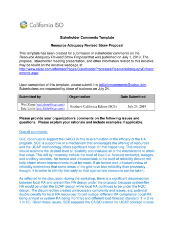
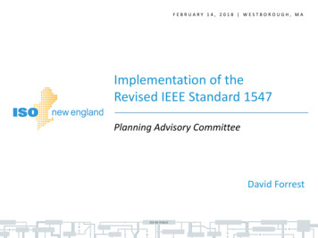
Voltage RiseClause 3.3.3 states that, Under normal service conditions, the voltage at the terminals of any power consumingelectrical equipment shall not be greater than the higher limit specified in the relevantelectrical equipment Standard. The overall voltage rise from the point of supply to the inverter a.c. terminals (gridinteractive port) shall not exceed 2% of the nominal voltage at the point of supply. The value of the current used for the calculation of voltage rise shall be the ratedcurrent of the IES.creating sustainable change through education, communication and leadership 2010 GSES P/L
Voltage Risecreating sustainable change through education, communication and leadership 2010 GSES P/L
Isolation SwitchesClause 3.4.3 states that, an isolation switch or circuit-breaker shall: be provided on the switchboard to which the IES is directly connected be able to be secured in the open position operate in all active conductors be capable of breaking the rated current of the IES isolate the IES from that switchboard be installed in accordance with the requirements for main switches as per AS/NZS 3000include the prohibition on the use of solid state devices for isolation be clearly labelledcreating sustainable change through education, communication and leadership 2010 GSES P/L
Central and inverter integratedprotectionAs per clause 3.4.4, Central protection shall be installed to perform the following functions—(a) coordinate multiple IES installations at the one site;(b) provide protection for the entire IES installation;(c) provide islanding protection to the connected grid; and(d) preserve safety of grid personnel and the general public.Any central protection shall be placed as close to the main switch (grid supply) of theinstallation as practicable. This protection is in addition to and separate from the inverterprotection.From table 1 of the AS/NZS4777.1 : 2016, additional central protection is required for thefollowing – 15kVA IES 30kVA : Phase balance protection where not integrated in the inverter 30kVA IES 200kVA : Phase balance protection where not integrated in the inverter andUnder/over voltage /frequency protection.creating sustainable change through education, communication and leadership 2010 GSES P/L
Phase Balance ProtectionClause 3.4.4.2 states that, Phase Balance Protection shall respond to current imbalance at the IES connection pointcaused by an IES (or multiple IES) between phases greater than 21.7A (5 kVA at 230 V) bydisconnecting all IES from the installation by automatic operation of a disconnectiondevice located adjacent to the main switch (Inverter supply) or adjacent to the invertersand/or the internal inverter disconnection device by asserting DRM 0 to the inverter. The disconnection device shall operate when there is loss of power to the centralprotection, loss of control signal from the central protection or an internal fault in thecentral protection. Phase balance protection shall operate within 30 seconds.creating sustainable change through education, communication and leadership 2010 GSES P/L
Central Voltage and Frequency ProtectionRequirementsSetting ParameterDisconnection timeIn Australia onlyIn New Zealand onlySustained overvoltage (V )*15 seconds255 V246 VOver voltage (V )2 seconds260 V250 VUnder voltage (V )2 seconds180 V180 VOver frequency (F )2 seconds52 Hz52 HzUnder frequency (F )2 seconds47 Hz45 HzTable 2, AS/NZS 4777.1:2016creating sustainable change through education, communication and leadership 2010 GSES P/L
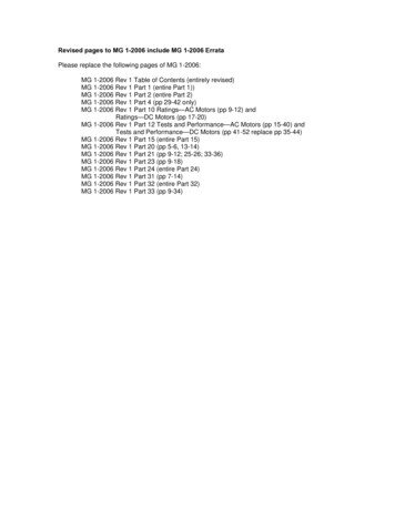
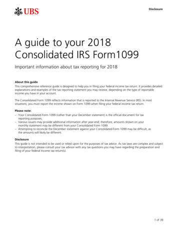
Residual Current Devices(RCDs)Clause 3.4.5 use of a dedicated RCD between the IES and the MSB, is now permittedas a means to meet mechanical cable protection requirements for grid-connect onlyinverters.However, this configuration is not allowed on a multiple mode inverter with standalonefunctionality in use.If the multiple mode inverter disconnects the stand-alone port neutral conductor from themain installation neutral when it switches to stand-alone mode, it will remove both theearth reference required for RCDs (whether RCCB or RCBO) to operate in earth leakagemode, which can then create shock hazardsThe RCD shall: disconnect all live conductors (including the actives and neutral) be of the type specified in the inverter manufacturer’s instructions or as labelled on theinverter.creating sustainable change through education, communication and leadership 2010 GSES P/L
creating sustainable change through education, communication and leadership 2010 GSES P/L
Export Control of an IESClause 3.4.8 states that, the export control for an IES is used to control the generation froman IES and amount of energy exported from an electrical installation to the grid. The exportcontrol function may be integrated into the inverter or an external device.The export control function for an IES may operate with the following export limits: Hard limit: A limit that will require the IES to disconnect. Soft limit: A limit that will cause the IES to reduce its output, preventing ongoing exportgreater than the limit.creating sustainable change through education, communication and leadership 2010 GSES P/L
Hard LimitClause 3.4.8.2 states that the hard limit of an export control function may apply to an IESthat has a capacity greater than 30 kVA. Where the limit is in total kVA, or total kW for multi-phase systems, this shall be thenet amount at the point of supply across all phases. For both single and three-phase systems, the export function shall monitor the exporton each phase.creating sustainable change through education, communication and leadership 2010 GSES P/L
Hard Limit When export control function is an external device: Where the net export limit is exceeded, the export control function shall ensure theIES has completed operating the disconnection device within two seconds. If the IES loses its connection with the export control device, the IES shall operate itsdisconnection device. When export control function is integrated into inverter: Where the net export limit is exceeded, the export control function shall be used todisconnect the IES and cease exporting within two seconds. If the IES loses its connection with external devices required for the export controlfunction, the IES shall operate its disconnection device.creating sustainable change through education, communication and leadership 2010 GSES P/L
Soft LimitClause 3.4.8.3 states that the soft limit of an export control function may apply to all typesof IES. Where the limit is in total kVA, or total kW for multi-phase systems, this shall be the netamount at the point of supply across all phases. Where the net export limit is exceeded, the export control function shall operate toensure the IES meets the export conditions within 15 seconds. If the IES and/or export control function loses its connection with the external device,the IES shall reduce IES output, to the limit setting as a maximum. The connection shallbe re-established and stable for a minimum of 60 seconds before the export controlfunction is restored.creating sustainable change through education, communication and leadership 2010 GSES P/L
Examplescreating sustainable change through education, communication and leadership 2010 GSES P/L
Overcurrent Protection Where the energy source is a PV array, AS/NZS 5033 shall be used to determine ifovercurrent protection is required and at which locations. All other energy source cabling shall be protected against overcurrent in accordancewith AS/NZS 3000. Where the energy system incorporates a battery storage system, overcurrent protectionshall be provided to protect, as far as practicable, all wiring from prospective shortcircuit current or overload current from the battery storage system. The wiring from the battery terminals to the overload protection device should be asshort as possible.creating sustainable change through education, communication and leadership 2010 GSES P/L
Isolation Devices A labelled isolation device, able to be secured in the open position, shall be providedbetween any energy source and the inverter. This device shall comply with the requirements of devices for isolation and switching inAS/NZS 3000 and be capable of safely breaking voltage and current under both normaland fault conditions. The isolation device shall be located adjacent to the inverter energy source port and bereadily available unless the energy storage and the inverter are physically integral, inwhich case the requirements of AS 62040.1.1 shall be adhered to. Where there are multiple inverter energy source ports, each port shall have an isolatorfor each connected energy source.creating sustainable change through education, communication and leadership 2010 GSES P/L
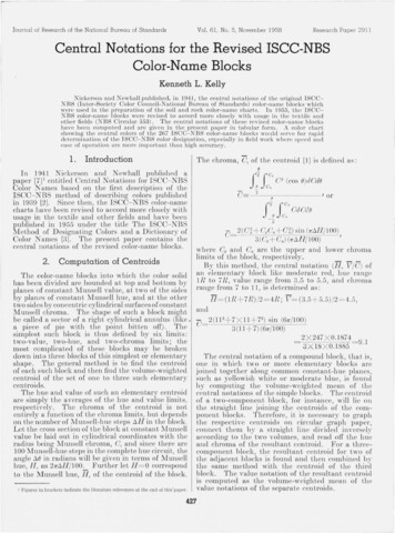
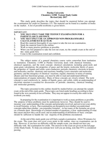
Segregation of CircuitsClause 5.2 states that, In addition to the requirements in AS/NZS 3000, segregation shall be provided betweend.c. and a.c. circuits within enclosures such that connections and pathways are physicallysegregated from each other by an insulating barrier. Where devices such as switches for circuits requiring segregation are mounted on acommon mounting rail in an enclosure, this rail shall not be metallic or conductive Segregation insulation barriers between the d.c. and a.c. circuits shall be equivalent todouble insulation for the highest voltage level present and appropriate for the installationenvironment. Outside of enclosures, a separation of 50 mm or a segregation insulation barrier betweena.c. and d.c. circuits shall be provided. Segregation insulation barriers between the d.c. and a.c. circuits shall be to theappropriate level for the installation environment and not less than IP4X.creating sustainable change through education, communication and leadership 2010 GSES P/L
Segregation of Circuitscreating sustainable change through education, communication and leadership 2010 GSES P/L
Multiple Mode IESThe inverter shall comply with the requirements of AS/NZS 4777.2 for multiple modeinverters with a stand-alone functionality.Typical Multiple mode IES with separate stand alone loads (Figure 3, AS/NZS 4777.1:2016)creating sustainable change through education, communication and leadership 2010 GSES P/L
Multiple Mode IESTypical Multiple mode IES with external disconnection device to separate from grid and provides stand alonesupplyNote: An external disconnection device is controlled by the multiple mode inverter that switchesfrom grid-connect mode to stand-alone mode. (Table 4, AS/NZS 4777.1:2016)creating sustainable change through education, communication and leadership 2010 GSES P/L
Multiple Inverter InstallationTypical Multiple Distribution Boards used as aggregation points for the IES then connected to a mainSwitchboard. (Figure 5, AS/NZS 4777.1:2016)creating sustainable change through education, communication and leadership 2010 GSES P/L
Multiple Inverter InstallationTypical Multiple Distribution boards used as aggregation points for the IES then connected to a distributionswitchboard (Figure 6, AS/NZS 4777.1:2016)creating sustainable change through education, communication and leadership 2010 GSES P/L
SignageTypical sign for the switchboard to whichthe IES is connectedTypical sign for a main switchboard orintermediate distribution switchboardswhen the IES is connected to a subsequentdistribution switchboardTypical labelling of energy source located atisolation pointExample battery energy source labelLocated on battery enclosurecreating sustainable change through education, communication and leadership 2010 GSES P/L
SignageExample label where specific operationalConsiderations for isolation existExample of energy storage label required atmain switchboard for emergency workersExample of demand response labelling oninverter showing DRM functions availableTypical warning sign for main switchboardand Intermediate distribution boardscreating sustainable change through education, communication and leadership 2010 GSES P/L
AS/NZS 4777.2: 2015- GRID CONNECTION OFENERGY SYSTEMS VIA INVERTERS - INVERTERREQUIREMENTScreating sustainable change through education, communication and leadership 2010 GSES P/L
Scope This Standard specifies requirements and tests for low voltage inverters for the injectionof electric power through an electrical installation into the grid at low voltage. ThisStandard applies to inverters that have power flow in either direction between theenergy source and the grid. This Standard needs to be read in conjunction with the regulations, service andinstallation rules of the electricity distributor approving the connection. This Standardshould also be read in conjunction with AS/NZS 3000.creating sustainable change through education, communication and leadership 2010 GSES P/L
Photovoltaic Array Earth Fault/Earth LeakageDetectionClause 5.3 states that, For inverter energy systems used with PV array systems that require earth fault detectionand a residual current detection, either internal or external to the inverter, the type ofdetection used shall be declared in accordance with IEC 62109-1 and IEC 62109-2. Where the additional detection for functionally earthed PV arrays, as required by AS/NZS5033, is present in the inverter, this additional detection shall, before start-up of the system: open circuit the functional earth connection to the PV array; measure the resistance to earth of each conductor of the PV array; if the earth resistance is above the resistance limit (Riso limit) threshold, the systemshall reconnect the functional earth and shall be allowed to start; if the earth resistance is equal to or less than the resistance limit (Riso limit) threshold,the inverter shall shut down and initiate an earth fault alarm in accordance with therequirements of IEC 62109-2.creating sustainable change through education, communication and leadership 2010 GSES P/L
Power FactorClause 5.5 states that, The displacement power factor of the inverter, considered as a load from theperspective of the grid, shall, for all current outputs from 25% to 100% of rated current,operate at unity power factor within the range 0.95 leading to 0.95 lagging. Operation at power factor other than unity is acceptable where the inverter operates inpower quality response modes.creating sustainable change through education, communication and leadership 2010 GSES P/L
Harmonic CurrentsClause 5.6 states that ,the harmonic currents of the inverter shall not exceed the limitsspecified in the tables below. The total harmonic current distortion to the 50th harmonicshall be less than 5%.Odd harmonicorder numberLimit for eachindividual oddharmonic basedon percentage offundamentalEven harmonicorder numberLimit for eachindividual evenharmonic basedon percentage offundamental3,5 and 74%2,4,6 and 81%9,11 and 132%15,17 and 191%10,12,14,16,18,20, 0.5%22,24,26,28,30and 3221,23,25,27,29,31and 330.6%creating sustainable change through education, communication and leadership 2010 GSES P/L
DC Current InjectionClause 5.9 states that In the case of a single-phase inverter, the d.c. output current of the inverter at any a.c.port including the grid-interactive and/or stand-alone port shall not exceed 0.5% ofthe inverter’s rated current or 5 mA, whichever is the greater. In the case of a three-phase inverter, the d.c. output current of the inverter at any a.c.port, including the grid-interactive and/or stand-alone port, measured in each of thephases, shall not exceed 0.5% of the inverter’s per-phase rated current or 5 mA,whichever is the greater. For any inverter capable of injecting d.c. fault current into the electrical installationthe selection of an RCD, where required, needs to be such that the RCD operatescorrectly with the level of d.c. fault current being injected.creating sustainable change through education, communication and leadership 2010 GSES P/L
Current Balance for ThreePhase InverterClause 5.10 states that In the case of a three-phase inverter the a.c. output current shall be generated andinjected into the three-phase electrical installation as a three-phase balanced current. The a.c. output current for each phase for three-phase balanced current shall be within5% of the measured value of the other phases at rated current when injected into abalanced three phase voltage.creating sustainable change through education, communication and leadership 2010 GSES P/L
Inverter Demand Response Modes(DRMs)ModeRequirementDRM 0Operate the disconnection deviceDRM 1Do not consume powerDRM 2Do not consume at more than 50% of rated powerDRM 3Do not consume at more than 75% of rated power and source reactive power if capableDRM 4Increase power consumption (subject to constraints from other active DRMs)DRM 5Do not generate powerDRM 6Do not generate at more than 50% of rated powerDRM 7Do not generate at more than 75% of rated power and sink reactive power if capable.DRM 8Increase power generation (subject to constraints from other active DRMs)NOTE: Demand response modes of Table 5 are as described in AS/NZS 4755.3 series of StandardsDemand Response Management is defined as being the automated alteration of an electrical product’s normal mode of operationin response to an initiating signal originating from or defined by a remote agent. (Table 5, AS/NZS 4777.2:2015)creating sustainable change through education, communication and leadership 2010 GSES P/L
Demand Response EnablingDevice (DRED)Clause 6.2.2 states that, A Demand Response Enabling Device (DRED) acts to provide the interface betweenthe remote agent (i.e. the grid) and the demand controller built into the inverter. DREDs must be connected to the DRM port of the inverter as per the manufacturer sguidelines. In some of the cases where a DRM port is not available, DREDs should beinstalled according to manufacturer s specifications. The communication cabling forsuch devices shall be protected and isolated from other cables.creating sustainable change through education, communication and leadership 2010 GSES P/L
InverterPowerResponse ModesQualityClause 6.3.1 states that, Inverters may be capable of providing support to the grid byworking outside the typical operating characteristics of an inverter. There various operatingmodes may be enabled or disabled in the inverter and may include following: Volt response modesFixed power factor or reactive power modePower response modePower rate limitcreating sustainable change through education, communication and leadership 2010 GSES P/L
Volt Response ModeClause 6.3.2 states that the mode responds to voltage changes at the inverter terminals andhelps to increase the number of systems that can be connected at a point on the gridwithout affecting the voltage within an electrical installation. Each of the voltage responsemodes may be programmed for different response values from the other modes, thusallowing for different response curves in different modes to suit local distributorrequirements.ReferenceAustralian Default Value (V)Range (V)V1207NAV2220216 to 230V3250235 to 255V4265244 to 265Volt Response Reference Values (Table 9, AS/NZS 4777.2:2015)creating sustainable change through education, communication and leadership 2010 GSES P/L
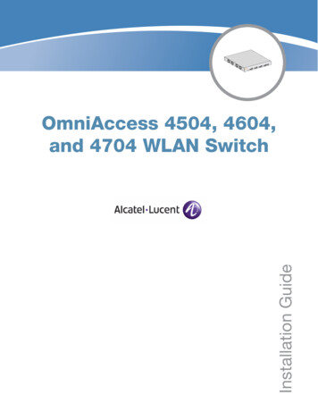
Volt Watt Response ModeClause 6.3.2.2 states that in this mode,the output power of the inverter isvaried in response to terminal voltage. Ifthis mode is available, it shall beenabled by default. The table belowshows the maximum set point values forreference voltages.ReferenceMaximum Value (P/Prated), %V1100%V2100%V3100%V420%Figure 2(A), AS/NZS 4777.2:2015Table 10, AS/NZS 4777.2:2015creating sustainable change through education, communication and leadership 2010 GSES P/L
Volt Var Response ModeClause 6.3.2.3 states that, In this mode,the reactive power output of theinverter is varied in response to thevoltage at its grid interactive port.Some inverters include an optional VoltVAr response capability which isdisabled by default.ReferenceDefault valuesfor VAr level(VAr % ratedVA)MinimumRangeV130% leadingV20%0 to 60%leading0%V30%0%V430% lagging0 to 60 %laggingFigure 3, AS/NZS 4777.2:2015Table 11, AS/NZS 4777.2:2015creating sustainable change through education, communication and leadership 2010 GSES P/L
Voltage Balance ModeClause 6.3.2.4 states that, Voltage balancing mode is where a three-phase inverter or single-phase inverters usedin a three-phase combination are used to balance the voltages between phases on acustomer’s installation by injecting unbalanced three-phase currents into theinstallation. For example if “A” phase is more heavily loaded than “B” and “C” phases, the voltage on“A” phase would normally drop in comparison to “B” and “C” phases. By injecting morecurrent into the “A” phase than into the “B” and “C” phases the heavier load is offsetand the installation voltage is balanced. The voltage balance mode must be able to detect faults and either: operate correctly with a single fault applied disconnect the inverter from the electrical installation for three phase inverters, force the inverter to revert to injecting current into thethree phase electrical installation as a three phase balanced current.creating sustainable change through education, communication and leadership 2010 GSES P/L
Power Rate LimitClause 6.3.5 states that, The power rate limit for an inverter is a power quality response mode which states thatinverter shall have the capability to rate limit changes in power generation through gridinteractive mode. The power rate limit does not apply when the inverter disconnection device is requiredto operate. The power rate limit causes the inverter power output to either ramp up or ramp downsmoothly as it transitions from one power output level to another power output level. These changes in power output level are constrained by several factors such as thetype of energy source connected, energy storage and operating state of the inverter. Ramp rates are adjustable between 5% and 100% of rated power per minute and maybe different for ramp up to that for ramp down.creating sustainable change through education, communication and leadership 2010 GSES P/L
Fixed Power Factor Mode and Reactive PowerModeClause 6.3.3 states that, The fixed power factor mode and the reactive power mode may be required in somesituations by the electrical distributor to meet local grid requirements and should bedisabled by default. If the inverter is capable of operating with reactive power mode, the maximum ratio ofreactive power (VARs) to rated apparent power should be 100%. If the inverter is capable of operating with fixed power factor mode, the minimum rangeof settings should be 0.8 leading to 0.8 lagging.creating sustainable change through education, communication and leadership 2010 GSES P/L
Multiple Mode InverterOperationClause 6.4.1 states that, When the multiple mode inverter is disconnected from the grid any stand-alone portshall ensure that all active conductors are also isolated from the grid-interactive port. Multiple mode inverters shall be arranged to ensure that the continuity of the neutralconductor to the load from the electrical installation is not interrupted when theinverter disconnects from the grid and supplies a load via the stand-alone port. Multiple mode inverters shall be arranged such that only the allowed installationmethods of AS/NZS 3000 and AS/NZS 4777.1 can be used. The a.c. output voltage waveform of a stand-alone mode shall have a voltage totalharmonic distortion (THD) not exceeding of 5% and no individual harmonic at a levelexceeding 5%.creating sustainable change through education, communication and leadership 2010 GSES P/L
Active Anti-Islanding ProtectionClause 7.3 states that, the automatic disconnection device shall incorporate at least onemethod of active anti-islanding protection such as : Frequency Shift: shifting the frequency of the inverter away from nominal conditions inthe absence of a reference frequency Frequency Instability: allowing the frequency of the inverter to be inherently unstablein the absence of a reference frequency Power Variation: periodically varying the output power of the inverter Current Injection: monitoring for sudden changes in the impedance of the grid byperiodically injecting a current pulsecreating sustainable change through education, communication and leadership 2010 GSES P/L
Voltage and Frequency LimitsClause 7.4 states that the automatic disconnection device shall incorporate the following formsof passive anti-islanding protection: Undervoltage and overvoltage protection. Under-frequency and over-frequency protection.Protective FunctionProtective FunctionLimitTrip Delay TimeMaximumDisconnection TimeUndervoltage (V )180 V1s2sOvervoltage (V )260 V1s2sOvervoltage (V )265 V-0.2 sUnder frequency(F )47 Hz (Aus)45 HZ (NZ)1s2sOver frequency (F )52 Hz-0.2 sPassive Anti-islanding Set-point Values (Table 13, AS/NZS 4777.2:2015)creating sustainable
3000 and AS/NZS 3008.1.1. All the cables between the IES and any switchboard and all the cables between any distribution switchboards and the main switchboard that carry current from the IES shall have a current-carryi