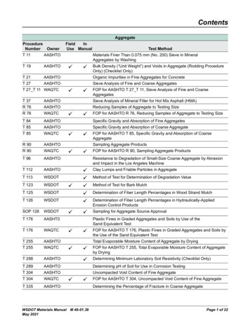
Transcription
State of CaliforniaDEPARTMENT OF TRANSPORTATIONCalifornia State Transportation AgencyMemorandumTo:STRUCTURE POLICY BOARDFrom:RUTH FERNANDESState Bridge Engineer (A)Deputy Division Chief (A)Structure Policy & InnovationDivision of Engineering ServicesSubject:Making Conservationa California Way of LifeDate:August 19, 2019ADOPTION OF THE AASHTO LRFD BRIDGE DESIGN SPECIFICATIONS, EIGHTHEDITION WITH CALIFORNIA AMENDMENTSEffective November 1, 2019, the AASHTO LRFD Bridge Design Specifications,Eighth Edition with California Amendments (AASHTO-CA BDS-8), constitutes theprimary design specifications for California bridges and transportation-relatedstructures.For projects under development, adoption of AASHTO-CA BDS-8 is: Mandatory for all projects with a Type Selection approval on or afterNovember 1, 2019. Optional if it would not impose a significant delay in the project scheduleor a significant increase in the project engineering or construction costs.The project history notes and plans must indicate the design criteria used.Caltrans’ Standard Plans and Standard Specifications remain valid for use. If aproject under development requires significant deviation from these standards,the design must meet the requirements of AASHTO-CA BDS-8.The State Bridge Engineer shall approve any exceptions to adopting provisions inthe AASHTO-CA BDS-8 as stated above. This request shall be made as early aspossible.AASHTO-CA BDS-8 shall be the basis of all Caltrans’ guidance material underdevelopment.“Provide a safe, sustainable, integrated and efficient transportation system to enhance California’s economy and livability”
STRUCTURE POLICY BOARDAugust 19, 2019Page 2For questions or concerns on the application of the AASHTO-CA BDS-8 on aspecific project, consultants and local agencies should contact the StructureLiaison Engineer. Caltrans’ staff may contact the appropriate TechnicalCommittee Chair or Technical Specialist.AASHTO-CA BDS-8 is available on the Caltrans’ Division of Engineering Serviceswebsite. If you are not able to locate AASHTO-CA BDS-8 or any other bridgemanual, please contact us at: manuals.products@dot.ca.gov.c:Thomas A. Ostrom, Acting Chief, Division of Engineering ServicesJanice Benton, Chief, Division of DesignSue Hida, Chief, DES SP&I Office of State Bridge Engineer SupportNina Choy, Chief, DES SP&I Office of Structure Quality ManagementMark Mahan, Chief, DES SP&I Office of Earthquake EngineeringJoel Magaña, Chief, DES SP&I Office of Design & Technical ServicesOffices of Bridge Design, DES SDSergio Aceves, Assistant Division Chief, Division of Pavements“Provide a safe, sustainable, integrated and efficient transportation system to enhance California’s economy and livability”
California Amendmentsto the AASHTO LRFD Bridge DesignSpecifications(2017 Eighth Edition)April 2019DEPARTMENT OF TRANSPORTATIONSTATE OF CALIFORNIA
ForewordIn 1993, the AASHTO Subcommittee on Bridge and Highway Structures(SCOBS) voted to accept the AASHTO LRFD Bridge Design Specifications as analternate design specification. In June 2000, FHWA mandated that LRFD beused on all new bridge design commencing on or after October 1, 2007 andprovided additional information in a clarification memorandum dated January 22,2007.In 1999, California Department of Transportation (Caltrans) began developingamendments to the AASHTO LRFD Bridge Design Specifications that werenecessary to adopt the national code into California’s bridge design practice. InDecember 2004, Richard D. Land, former State Bridge Engineer, establishedApril 2006 as the transition date to use the LRFD specifications for bridgesdesigned by the State. Similarly, October 2006 was established for using theLRFD specifications for bridges designed by Local Agencies or others locatedwithin state right-of-way.In April 2006, Kevin J. Thompson, State Bridge Engineer, confirmed that allstructural components for bridges designed by the State that had not receivedType Selection approval, shall conform to the AASHTO LRFD Bridge DesignSpecifications, 3rd Edition, with 2005 Interim Revisions, as amended by Caltrans.Similarly, October 1, 2006 was confirmed for the LRFD structural design forbridges, without Type Selection approval, designed by Local Agencies or otherslocated within state right-of-way. Full implementation of the complete theAASHTO LRFD Design Specifications including the geotechnical design offoundations was set for April 1, 2007 for bridges designed by the State andOctober 1, 2007 for bridges designed by others.In December 2008, Kevin J. Thompson, State Bridge Engineer, approved theAASHTO LRFD Bridge Design Specifications, 4th Edition with the CaliforniaAmendments, as the primary Caltrans bridge design specifications. InSeptember 2010, Tony Marquez, Deputy Division Chief, expanded thisrequirement to include earth retaining structures. In December 2011, BartonNewton, State Bridge Engineer approved updates to Sections 2, 3, 4, 5, 6, 10,11, 12, and 13.In March 2014, Barton Newton, State Bridge Engineer, approved the AASHTOLRFD Bridge Design Specifications, Sixth Edition with the CaliforniaAmendments, January 2014 as the primary Caltrans bridge design specifications.In August 2019, Ruth Fernandes, State Bridge Engineer (A), approved theAASHTO LRFD Bridge Design Specifications, 8th Edition with the CaliforniaAmendments as the primary Caltrans bridge design specifications. The LRFDSpecifications with the most current California amendments shall be the basis forall advance planning studies, geotechnical investigation, bridge design and otherproject supporting documentation and bridge design guidance material.CA-i
PREFACEtoCALIFORNIA AMENDMENTSCALTRANS STANDARD SPECIFICATIONS (CURRENT VERSION):Shall supersede all references to the AASHTO LRFD BridgeConstruction Specifications within the AASHTO LRFD Bridge DesignSpecifications. However, the AASHTO Construction Specifications arerecommended as reference.THE GENERAL PLAN TITLE BLOCK SHALL SPECIFY THE DESIGNLIVE LOAD AS:“Load and Resistance Factor Design”, and “HL93 w/ ‘Low-Boy’ andPermit Design Vehicle”THE GENERAL NOTES SHALL SPECIFY:“Load and Resistance Factor Design” and list the “AASHTO LRFD BridgeDesign Specifications, 8th edition with California Amendments”.CA-iiApril 2019
SECTION 1: INTRODUCTIONCALIFORNIA AMENDMENTS TO AASHTO LRFD BRIDGE DESIGN SPECIFICATIONS – 8TH EDITION1-3A1.2—DEFINITIONSReplace the definition:Service Life—The period of time that the bridge is expected to be in operation. The servicelife for new construction is considered to be 75 years unless otherwise specified.April 2019
SECTION 1: INTRODUCTIONCALIFORNIA AMENDMENTS TO AASHTO LRFD BRIDGE DESIGN SPECIFICATIONS – 8TH EDITION1-3BThis page intentionally left blank.April 2019
SECTION 1: INTRODUCTIONCALIFORNIA AMENDMENTS TO AASHTO LRFD BRIDGE DESIGN SPECIFICATIONS – 8TH EDITION1-5A1.3—DESIGN PHILOSOPHY1.3.3—DuctilityC1.3.3Replace the article with the following:Add a new last paragraph as follows:The structural system of a bridge shallbe proportioned and detailed to ensure thedevelopment of significant and visibleinelastic deformations at the strength limitstate before failure. The structural systemof a bridge shall be proportioned anddetailed to ensure a significant inelasticdeformation capacity at the extreme eventlimit state to ensure an extremely lowprobability of collapse.Energy-dissipating devices may besubstituted for or used to supplementconventional ductile earthquake resistingsystems and the associated methodologyaddressed in these Specifications or theAASHTO Guide Specifications for SeismicDesign of Bridges.A value of 1.0 is being used for ηDuntil its application is better defined.For all limit states:ηD 1.00April 2019
SECTION 1: INTRODUCTIONCALIFORNIA AMENDMENTS TO AASHTO LRFD BRIDGE DESIGN SPECIFICATIONS – 8TH EDITION1-6A1.3.4—RedundancyC1.3.4Replace the article with the following:Add a new last paragraph as follows:Multiple-load-path and continuousstructures should be used unless there arecompelling reasons not to use them.A value of 1.0 is being used for ηR untilits application is better defined.For all limit states:ηR 1.00April 2019
SECTION 1: INTRODUCTIONCALIFORNIA AMENDMENTS TO AASHTO LRFD BRIDGE DESIGN SPECIFICATIONS – 8TH EDITION1-7A1.3.5—Operational ImportanceC1.3.5Replace paragraphs 3 and 4 with thefollowing:Add a new last paragraph as follows:For all limit states:ηI 1.00A value of 1.0 is being used for ηI untilits application is better defined.April 2019
SECTION 1: INTRODUCTIONCALIFORNIA AMENDMENTS TO AASHTO LRFD BRIDGE DESIGN SPECIFICATIONS – 8TH EDITION1-7BThis page intentionally left blank.April 2019
SECTION 2: GENERAL DESIGN AND LOCATION FEATURESCALIFORNIA AMENDMENTS TO AASHTO LRFD BRIDGE DESIGN SPECIFICATIONS – 8TH EDITION2-5A2.3.2.2.2—Protection of UsersReplace the 3rd paragraph with thefollowing:In the case of movable bridges,warning signs, lights, signal bells, gates,barriers, and other safety devices shall beprovided for the protection of pedestrian,cyclists, and vehicular traffic. These shallbe designed to operate before theopening of the movable span and toremain operational until the span hasbeen completely closed. The devicesshall conform to the requirements for“Traffic Control for Movable Bridges,” inthe California Manual on Uniform TrafficControl Devices (CA MUTCD) or asshown on plans.2.3.2.2.3—Geometric StandardsReplace the article with the following:Requirements of the Caltrans HighwayDesign Manual shall either be satisfied orexceptions thereto shall be justified anddocumented. Width of shoulders andgeometry of traffic barriers shall meet thespecifications of the Owner.Add the following commentary:2.3.2.2.4—Road SurfacesReplace the article with the following:Road surfaces on a bridge shall begivencrown,drainage,andsuperelevation in accordance with theCaltrans Highway Design Manual or localrequirements.C2.3.2.2.4Bridge deck surface characteristicsare specified in Caltrans StandardSpecifications.April 2019
SECTION 2: GENERAL DESIGN AND LOCATION FEATURESCALIFORNIA AMENDMENTS TO AASHTO LRFD BRIDGE DESIGN SPECIFICATIONS – 8TH EDITION2-6A2.3.3.2—Highway VerticalReplace the article with the following:The vertical clearance of highwaystructures shall be in conformance with theCaltrans Highway Design Manual for theFunctional Classification of the Highway orexceptions thereto shall be justified.Possible reduction of vertical clearance,due to settlement of an overpass structure,shall be investigated. If the expectedsettlement exceeds 1.0 in., it shall beadded to the specified clearance.The vertical clearance to sign supportsand pedestrian overpasses shall be inconformance with the Caltrans HighwayDesign Manual.The vertical clearance from theroadway to the overhead cross bracing ofthrough truss structures should not be lessthan 17.5 ft.2.3.3.3—Highway HorizontalReplace the 2nd paragraph with thefollowing:Horizontal clearance under a structureshould meet the requirements of Article2.3.2.2.April 2019
SECTION 2: GENERAL DESIGN AND LOCATION FEATURESCALIFORNIA AMENDMENTS TO AASHTO LRFD BRIDGE DESIGN SPECIFICATIONS – 8TH EDITION2.6.4.4.2—Bridge ScourReplace the 3rd paragraph with thefollowing:Spread footings on soil or erodiblerock shall be located so that the top offooting is below the total scour elevationand the bottom of footing is below thescour depths determined for the checkflood for scour. Spread footings on scourresistant rock shall be designed andconstructed to maintain the integrity of thesupporting rock.2-21AC2.6.4.4.2Add the following after the 3rd paragraph:Total scour is the cumulative sum ofcontraction, degradation, and local scour.Figure C2.6.4.4.2-1 shows a typicalspread footing foundation.Replace the 4th paragraph with thefollowing:Deep foundations with footings shallbe designed to place the top of the footingbelow the estimated degradation pluscontraction scour depth where practical tominimize obstruction to flood flows andresulting local scour. Even lowerelevations should be considered for pilesupported footings where the piles couldbe damaged by erosion and corrosionfrom exposure to stream currents. Whereconditions dictate a need to construct thetop of a footing to an elevation above thetotal scour elevation, attention shall begiven to the scour potential of the designFigure C2.6.4.4.2-1 Spread FootingLocationAdd the following after the 4th paragraph:Foundations should be designed towithstand the conditions of scour. Ingeneral, this will result in deepfoundations. Figure C2.6.4.4.2-2 shows atypical deep foundation.Figure C2.6.4.4.2-2 Deep FoundationLocationApril 2019
SECTION 2: GENERAL DESIGN AND LOCATION FEATURESCALIFORNIA AMENDMENTS TO AASHTO LRFD BRIDGE DESIGN SPECIFICATIONS – 8TH EDITION2-21BThis page intentionally left blank.April 2019
SECTION 2: GENERAL DESIGN AND LOCATION FEATURESCALIFORNIA AMENDMENTS TO AASHTO LRFD BRIDGE DESIGN SPECIFICATIONS – 8TH EDITION2.6.6.3—Type, Size, and Numberof Drains2-23AC2.6.6.3Replace the 1st paragraph with thefollowing:For further guidance or design criteriaon bridge deck drainage, see theCaltrans Highway Design Manual, Memoto Designers, and Bridge Design Aids.April 2019
SECTION 2: GENERAL DESIGN AND LOCATION FEATURESCALIFORNIA AMENDMENTS TO AASHTO LRFD BRIDGE DESIGN SPECIFICATIONS – 8TH EDITION2-23BThis page intentionally left blank.April 2019
SECTION 3-LOADS AND LOAD FACTORSCALIFORNIA AMENDMENTS TO AASHTO LRFD BRIDGE DESIGN SPECIFICATIONS – 8TH EDITION3-8A3.3.2—Load and Load DesignationAdd the following notations:DCSub deadloadofstructuralcomponents and nonstructuralattachments of substructureDCSup deadloadofstructuralcomponents and nonstructuralattachments of superstructureESH earth surcharge horizontal loadESV earth surcharge vertical loadApril 2019
SECTION 3-LOADS AND LOAD FACTORSCALIFORNIA AMENDMENTS TO AASHTO LRFD BRIDGE DESIGN SPECIFICATIONS – 8TH EDITION3-8BThis page intentionally left blank.April 2019
SECTION 3-LOADS AND LOAD FACTORSCALIFORNIA AMENDMENTS TO AASHTO LRFD BRIDGE DESIGN SPECIFICATIONS – 8TH EDITION3.4.1—Load Factors and LoadCombinations3-9AC3.4.1Replace the following notation in the 1stparagraph:γi load factors specified in Tables3.4.1-1, 3.4.1-2, 3.4.1-3, 3.4.1-4,3.4.5.1-1 and 3.4.5.1-2.Replace the 2nd bullet in the 2nd paragraphwith the following: Strength II—Load combinationrelating to the use of the bridge byOwner specified special designvehicles, evaluation permit vehicles,or both without wind. The Caltransspecified special design vehicle andevaluation permit vehicle shall bethe Permit Vehicle as specified inArticle 3.6.1.8.Replace the 2nd paragraph with thefollowing:The vehicular braking force is notincluded in this load combination.April 2019
SECTION 3-LOADS AND LOAD FACTORSCALIFORNIA AMENDMENTS TO AASHTO LRFD BRIDGE DESIGN SPECIFICATIONS – 8TH EDITION3-9BThis page intentionally left blank.April 2019
SECTION 3-LOADS AND LOAD FACTORSCALIFORNIA AMENDMENTS TO AASHTO LRFD BRIDGE DESIGN SPECIFICATIONS – 8TH EDITIONReplace the 6th bullet of the 2nd paragraphof the article with the following: Extreme Event I – Load combinationincluding earthquake. The load factorfor live load, γEQ, shall be determinedon a project-specific basis foroperationally important structures.For standard bridges γEQ 0.03-10AReplace the 9th paragraph of thecommentary with the following:Vehicular live loads have not beenobserved to be in-phase with the bridgestructure during seismic events. Thus, theinertial effect of actual live loads on typicalbridges is assumed to be negligible.Bridges that were seismically retrofittedwithout consideration of vehicular loadsperformed well during the 1994 Northridgeearthquake.Replace the 4th bullet of the 10th paragraphof the commentary with the following: Although these limit states includewater loads, WA, the effects due toWA are considerably less significantthan the effects on the structurestability due to scour. Therefore,unless specific site conditionsdictate otherwise, local pier scourdepths should not be combined withBL, EQ, CT, CV, or, IC in thestructural or geotechnical design.However, the effects due todegradation and contraction scourofthechannelshouldbeconsidered.April 2019
SECTION 3-LOADS AND LOAD FACTORSCALIFORNIA AMENDMENTS TO AASHTO LRFD BRIDGE DESIGN SPECIFICATIONS – 8TH EDITION3-10BReplace the 5th bullet of the 10th paragraphof the commentary with the following: The joint probability of these eventsis extremely low, and, therefore, theevents are specified to be appliedseparately. Under these extremeconditions, the structure mayundergo considerable inelasticdeformation by which locked-inforce effects due to TU, TG, CR, SHand SE are expected to be relieved.The effects due to degradation andcontractionscour shouldbeconsidered for both structural andgeotechnical design.April 2019
SECTION 3-LOADS AND LOAD FACTORSCALIFORNIA AMENDMENTS TO AASHTO LRFD BRIDGE DESIGN SPECIFICATIONS – 8TH EDITIONReplace the 13th bullet of the 2ndparagraph of the article with the following: Fatigue II—Fatigue and fractureload combination related to finiteload-induced fatigue life due to onepermit truck (P9) specified in Article3.6.1.4.1.3-12AReplace the 23rd paragraph of thecommentary with the following:Finite fatigue life is the design concept usedfor lower traffic volume bridges. Theeffective fatigue stress range is kept lowerthan the fatigue resistance, which is afunction of load cycles and details, toprovide a finite fatigue life. The load factorfor the Fatigue II load combination, appliedto a single design truck, reflects a load levelfound to be representative of the permittruck population with respect to a smallnumber of stress range cycles and to theircumulative effects in steel elements,components, and connections for finitefatigue life design.Add the following after the 2nd paragraph ofthe article:Load combinations applicable toabutment construction conditions havebeen added as cases I and II: Construction I - Load combinationrelated to the construction conditionwhere the abutment has been builtbut the superstructure has not beenconstructed. For post-tensionedsuperstructures, when consideringConstruction I load combination,lateral soil pressure shall becalculated using the height of theabutment below the backwall.Construction II- Load combinationrelated to construction condition,where soil surrounding the abutmenthas been removed for repair,widening, or other reasons after thesuperstructurehasbeenconstructed.April 2019
SECTION 3-LOADS AND LOAD FACTORSCALIFORNIA AMENDMENTS TO AASHTO LRFD BRIDGE DESIGN SPECIFICATIONS – 8TH EDITION3-12BThis page intentionally left blank.April 2019
SECTION 3-LOADS AND LOAD FACTORSCALIFORNIA AMENDMENTS TO AASHTO LRFD BRIDGE DESIGN SPECIFICATIONS – 8TH EDITION3-15AReplace the 10th paragraph of the articlewith the following:The load factor for settlement, γSE, shallbe taken as:1. For predefined settlements used forgeotechnical design of foundations,that is 1.0 in. for continuous spansand simple spans with diaphragmabutments and 2.0 in. for simplespans with seat abutments: Whengeotechnicalinformation indicates thatactual differential settlementis not expected to exceed 0.5in., settlement does not needto be considered in thedesign of the superstructure. Whengeotechnicalinformation indicates thatdifferential settlement is likelyto exceed 0.5 in., forceeffects due to predefinedsettlements shall be includedin the design of thesuperstructure, and the loadfactor γSE shall be taken as0.5 and 0.0.2. For refined analysis using nonlinearsoil springs, the force effects due tosettlement are directly included inthe structural analysis. In that casesettlement load factor γSE shall betaken as 1.0 and 0.0.April 2019
SECTION 3-LOADS AND LOAD FACTORSCALIFORNIA AMENDMENTS TO AASHTO LRFD BRIDGE DESIGN SPECIFICATIONS – 8TH EDITION3-15BReplace Table 3.4.1-1 with the following:Table 3.4.1-1―Load Combinations and Load FactorsDCDDDWEHEV LLHL-93ESIMELCEPSBR LLPermitLoadPLIMCombination CRLSCEWALimit State SHSTRENGTHI(unless SERVICEIVFATIGUEILLHL-93, IM &CE onlyFATIGUEIILLPermit , IM &CE onlyUse One of These at aTimeWSWLFRTUTGSEEQBLICCTCVγp1.7501.00001.00 �p001.00 1.0001.00 0.50/1.201.00 0.50/1.20γTGγSE00000γp001.0001.00 0.50/1.200000000γp1.3501.00 1.00 1.00 1.00 001.000.5001.00001.0000001.001.0001.00 1.00 1.00 1.00 1.00/1.20γTGγSE000001.001.3001.00001.00 1.00/1.2000000001.00γLL01.00001.00 1.00/1.20γTGγSE000001.00001.00 1.00001.000000001.7500001.00 1.00/1.20000000000001.0000000000000001.00 1.00 1.00 1.00April 2019
SECTION 3-LOADS AND LOAD FACTORSCALIFORNIA AMENDMENTS TO AASHTO LRFD BRIDGE DESIGN SPECIFICATIONS – 8TH EDITION3-18AAdd Article 3.4.5 as follows:3.4.5—Load Factors for AbutmentsAbutments shall be designed for theService, Strength, Extreme Event, andConstruction limit states specified inArticles 3.4.5.1 and 3.4.5.2. The maximumhorizontal shear force transferred from thesuperstructure to a non-integral abutmentmay be assumed as 20% of the sum of theDC and DW reactions, that is 0.2(DC DW).For this shear force, a load factor of 1.25shall be used for both DC and DW for theStrength Limit State combinations.3.4.5.1—Service, Strength, andConstruction Load CombinationsAbutments shall be designed for theService-I load combination in Table 3.4.1-1and the Strength, and Construction loadcombinations specified in Table 3.4.5.1-1.For γp values of abutments refer to Table3.4.5.1-2. For dynamic load allowance (IM)of abutments, refer to Article 3.6.2.1.Table 3.4.5.1-1—Strength and Construction Load Factors for AbutmentsLLHL93IMCEBRPLLS1.75LLPermitIMCEWA01.00WS WL00PSCRSTUH1.00 1.00Strength IDCSup DCSub DDγpγpγpDWγpEH,ESHEVESVγpStrength IIγpγpγpγpγp01.351.00001.001.00Strength IIIγpγpγpγpγp001.001.0001.001.00Strength ion I0γp00γp0000000Construction II1.251.2501.500000001.001.00CombinationApril 2019
SECTION 3-LOADS AND LOAD FACTORSCALIFORNIA AMENDMENTS TO AASHTO LRFD BRIDGE DESIGN SPECIFICATIONS – 8TH EDITION3-18BTable 3.4.5.1-2—Load Factors for Permanent Loads, γp (for Abutments)Type of Load and Method Used to Calculate DowndragDCSub: Dead Load of Structure Components and NonstructuralAttachments of SubstructureDCSup: Dead Load of Structure Components and NonstructuralAttachments of SuperstructurePile, α Tomlinson MethodDD: DowndragPile, λ MethodDrilled Shaft, O’Neill and Reese (2010) MethodDW: Dead load of Wearing Surface and UtilitiesEH: Active Horizontal Earth PressureESH: Earth Surcharge Horizontal LoadESv: Earth Surcharge Vertical LoadEV: Vertical Earth PressureLoad 3.4.5.2—Extreme Event-I (Seismic)Load CombinationIf an abutment in Type S1 (as defined inArticle 6.1.2 of SDC version 2.0) soil meetsthe following height limitations, seismicforces shall be considered only in globalstability analysis of the abutment: The height measured from thesuperstructure deck to the bottom ofthe stem is not greater than 36 ft fornon-integral abutments. The height measured from thesuperstructure soffit to the bottom ofthe stem is not greater than 10 ft forintegral abutments.Components of abutments such as shearkeys are checked for seismic effects perCaltrans Seismic Design Criteria (SDC).Abutments that do not meet the abovelimitations and/or are located in Type S2(as defined in Article 6.1.3 of SDCversion 2.0) soil require special analysis.April 2019
SECTION 3-LOADS AND LOAD FACTORSCALIFORNIA AMENDMENTS TO AASHTO LRFD BRIDGE DESIGN SPECIFICATIONS – 8TH EDITION3-19A3.5.1—Dead Loads: DC, DW, and EVAdd the following after the 2nd paragraph:The dead load, DC, of cast-in-placeconcrete decks between precast concreteand steel girder flange edges shall beincreased by 10 percent.A future wearing surface load of 35 psfof roadway shall be included in thesuperstructure dead load, DW. This load isin addition to any surface or deck sealprovided in the structure.April 2019
SECTION 3-LOADS AND LOAD FACTORSCALIFORNIA AMENDMENTS TO AASHTO LRFD BRIDGE DESIGN SPECIFICATIONS – 8TH EDITION3-19BThis page intentionally left blank.April 2019
SECTION 3-LOADS AND LOAD FACTORSCALIFORNIA AMENDMENTS TO AASHTO LRFD BRIDGE DESIGN SPECIFICATIONS – 8TH EDITION3-23A3.6.1.2.6a—GeneralReplace the 2nd and 3rd paragraphs withthe following:Live load shall be distributed to the topslabs of flat top three-sided, box, or longspan concrete arch culverts with less than2.0 ft of fill as specified in Article 4.6.2.10.For unique situations, such as existingculverts or extensions, round culverts withless than 1.0 ft of fill shall be analyzed withmore comprehensive methods such asfinite element method considering soilstructure interaction.Where the depth of fill over roundculverts is greater than 1.0 ft, or when thedepth of fill over flat top three-sided, box, orlong-span concrete arch culverts is 2.0 ft orgreater the live load shall be distributed tothe top surface of the structure as wheelloads, uniformly distributed over arectangular area with sides equal to thedimension of the tire contact area specifiedin Article 3.6.1.2.5 increased by the liveload distribution factors (LLDF) specified inTable 3.6.1.2.6a-1, and the provisions ofArticles 3.6.1.2.6b and 3.6.1.2.6c. Moreprecise methods of analysis may be used.April 2019
SECTION 3-LOADS AND LOAD FACTORSCALIFORNIA AMENDMENTS TO AASHTO LRFD BRIDGE DESIGN SPECIFICATIONS – 8TH EDITION3-24AReplace Table 3.6.1.2.6a-1 with thefollowing:Table 3.6.1.2.6a-1—Live LoadDistribution Factor (LLDF) for BuriedStructuresStructure TypeLLDF Transverse or Parallel toSpanConcrete Pipes1.15 for diameters 2.0 ft or less1.75 for diameters 8.0 ft orgreaterLinearly interpolate for LLDFbetween these limitsAll other culvertsand buriedstructures1.153.6.1.2.6b—Traffic Parallel to theCulvert SpanReplace the equation 3.6.1.2.6b-1 with thefollowing:Hint-t sw -wt 0.06Di1212LLDF(3.6.1.2.6b-1)April 2019
SECTION 3-LOADS AND LOAD FACTORSCALIFORNIA AMENDMENTS TO AASHTO LRFD BRIDGE DESIGN SPECIFICATIONS – 8TH EDITION3-25AReplace equation 3.6.1.2.6b-6 with thefollowing: where H Hint-p :lw lt12 sa LLDF(H)(3.6.1.2.6b-6)April 2019
SECTION 3-LOADS AND LOAD FACTORSCALIFORNIA AMENDMENTS TO AASHTO LRFD BRIDGE DESIGN SPECIFICATIONS – 8TH EDITION3.6.1.3.1—GeneralAdd a 4th bullet to the 1st paragraph asfollows: For negative moment betweenpoints of contraflexure under auniform load on all spans, andreaction at interior piers only, 100percent of the effect of two designtandems spaced anywhere from26.0 ft to 40.0 ft from the rear axle ofthe leading tandem to the lead axleof the other, combined with 100percent of the design lane loadspecified in Article 3.6.1.2.4. Thetwo design tandems shall be placedin adjacent spans to producemaximum force effects.3-26AC3.6.1.3.1Replace the 3rd paragraph with thefollowing:The notional design loads were basedon the information described in ArticleC3.6.1.2.1, which contained data on “lowboy” type vehicles weighing up to about110 kip. In California, side-by-sideoccurrences of the “low boy” truckconfiguration are routinely found. Thisamendment is consistent with Article3.6.1.2.1, will control negative bendingserviceability in two-span continuousstructures with 20-ft to 60-ft span lengths,and should not be considered areplacement for the Strength II LoadCombination.April 2019
SECTION 3-LOADS AND LOAD FACTORSCALIFORNIA AMENDMENTS TO AASHTO LRFD BRIDGE DESIGN SPECIFICATIONS – 8TH EDITION3.6.1.3.3—Design Loads for Decks,Deck Systems, and the Top Slabs ofBox Culverts.3-27AC3.6.1.3.3Add a new 5th paragraph as follows:The force effects due to one 32.0-kipaxle on the strip-widths specified in Table4.6.2.1.3-1, were found to be similar toCaltrans’ past practice and envelope two24.0-kip axles spaced 4’-0” on center(design tandem). Also, the 54.0-kip tandemaxle of the permit vehicle typically doesn’tcontrol deck designs when applying theappropriate load factors or allowablestresses.April 2019
SECTION 3-LOADS AND LOAD FACTORSCALIFORNIA AMENDMENTS TO AASHTO LRFD BRIDGE DESIGN SPECIFICATIONS – 8TH EDITION3-28A3.6.1.4—Fatigue LoadC3.6.1.4.13.6.1.4.1—Magnitude andConfigurationReplace the 1st paragraph with thefollowing:For the Fatigue I limit state, the fatigueload shall be one design truck or axlesthereof specified in Article 3.6.1.2.2, butwith a constant spacing of 30.0 ft. betweenthe 32.0-kip axles.Add the following after the 2nd paragraph:Add the following paragraph:For the Fatigue II limit state, the fatigueload, LLpermit, shall be one permit truck,P9, as specified in Figure 3.6.1.4.1-2.The permit truck, P9, specified inFigure 3.6.1.4.1-2 represents the majorityof permit trucks allowed in California.(a)(b)Figure 3.6.1.4.1-2 — Permit Truck, P9April 2019
SECTION 3-LOADS AND LOAD FACTORSCALIFORNIA AMENDMENTS TO AASHTO LRFD BRIDGE DESIGN SPECIFICATIONS – 8TH EDITION3.6.1.4.2—Frequency3-29AC 3.6.1.4.2Add the following as the last 2 paragraphs:Add the following as the last paragraph:All bridges shall be designed for loadinduced infinite fatigue life as specified inFatigue I Limit State. If the Caltransapproved ADTTSL is less than the 75-year(ADTT)SL as specified in Table 6.6.1.2.3-2,then a live load factor of 0.8 and nominalfatigue resistance as specified in Eq.(6.6.1.2.5-2) shall apply.An (ADTT)SL of 2500 for the designfatigue truck as specified in Article 3.6.1.4.1has been successfully used for designingnew structures and widenings in California.Since the number of stress cycles causedby an ADTT of 2500 is greater than thatcaused by a 75-year (ADTT)SL satisfyinginfinite life, all bridges are designed forload-induced infinite fatigue life asspecified in Fatigue I Limit State. Based onvariation of si
EDITION WITH CALIFORNIA AMENDMENTS Effective November 1, 2019, the AASHTO LRFD Bridge Design Specifications, Eighth Edition with California Amendments (AASHTO-CA BDS-8), constitutes the primary design specifications for California bridges and transportation-related structures. For pr