Transcription
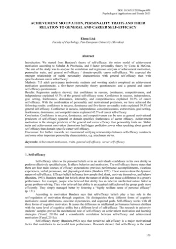
MODEL AND SIMULATION SCALABILITY TRAITS FOR INTERACTION (NEXUS)MODELING OF WATER AND ENERGY SYSTEMSMostafa D. FardHessam S. SarjoughianArizona Center for Integrative Modeling & SimulationSchool of Computing and Augmented IntelligenceArizona State UniversityTempe, AZ, USAABSTRACTIt is beneficial to combine simulation models via I/O data exchanges. The Knowledge Interchange Broker(KIB) modeling approach can be used to develop interaction models that also have time, state, operations,and concurrency. A unique advantage of the interaction model is the composed models can have their ownspecifications. The KIB is used to model the nexus of the water and energy models of city metropolises.The RESTful WEAP, LEAP, and DEVS-Suite are used to model and simulate the composition of hybridwater, nexus, and energy models. The performance measurements of the simulations of these integratedsimulators are evaluated. The results show the DEVS and Algorithmic interaction models have nearlyidentical computational times. These simulation times are contrasted with the use of links that share databetween WEAP and LEAP models. This research highlights the interaction model flexibility and visibilityat almost twice the computational time cost for data sharing.Keywords: Hybrid Models, Interaction Models, Knowledge Interchange Broker, Water-Energy Systems.1INTRODUCTIONEffective management of interdependent water and energy systems is critical to sustainable developmentfor cities, countries, regions, and the entire planet. Over the past few decades, analyzing issues within theWater-Energy Nexus (WEN) has become a topic of increasing attention for the scientific and policycommunities (Dai et al. 2018). The rapid population, urban growth, and global economic developmentadversely affect limited natural and man-made resources, including water, energy, food, and land. Modelingthe WEN is a challenging endeavor that requires extensive data on specific study areas (Zhang et al. 2019).Furthermore, the water and energy systems have bi-directional dependencies. For example, water is neededto cool the power plants, and energy is required to pump, treat, and distribute water. In addition to theseinternal interactions between the systems, external factors such as climate change, population growth, andeconomic instabilities increase the complexity of the Water-Energy system.Domain experts can participate in collective work using existing tools to better use previously acquiredknowledge and experience. Frameworks reduce the effort and resources needed for model development andsimulation studies. The proprietary Water Evaluation and Planning (WEAP) (Sieber, Swartz, and HuberLee 2005) and Low Emissions Analysis Platform (LEAP) (Heaps 2022) tools used in this research arespecialized for modeling, simulating, and evaluating the water and energy systems.ANNSIM’22, July 18-20, San Diego, CA, USA; 2022 Society for Modeling & Simulation International (SCS)
Fard and SarjoughianIn this paper, we detail the use of a DEVS-Based Interaction Model (DEVS-IM) (Fard and Sarjoughian2021b) developed for composing models defined using the WEAP and LEAP systems. We show the nexusof the water and energy models can be modeled independently to create flexible and scalable WEN models.This paper demonstrates the use of the DEVS-IM framework for composing the water and energy modelsof the Phoenix Active Management Area (Phoenix AMA) at scale. We also evaluate the computational costof the RESTful Componentized WEAP (Fard and Sarjoughian 2021a) and Componentized LEAPsimulators with a RESTful DEVS-Suite simulator relative to the Algorithmic-IM (Fard and Sarjoughian2020) and the internally linked WEAP & LEAP systems for the Phoenix AMA (Fard et al. 2020).2BACKGROUND2.1 WEAP & LEAP Tools with their Internal LinkageThe Water Evaluation and Planning (WEAP) system is a tool for modeling, simulating, and evaluatingwater systems. Models are defined as a network of water supply and demand entities (nodes) that areconnected via transportation entities (links). A WEAP model defines water allocation from different sourcesthrough preferences and mass balance constraints. The WEAP tool is widely used globally for waterallocation and management (Gao, Christensen, and Li 2017; Psomas et al. 2016; Amin et al. 2018). TheLow Emissions Analysis Platform (LEAP) system is an integrated modeling and simulation tool that canbe used to calculate energy consumption, production, and extraction in all sectors of an economy.The structure of the WEAP and LEAP models are defined using different types of entities (e.g., River,Demand Site, and Reservoir in the WEAP system; and Demand, Transformation, and Resource in the LEAPsystem) with their Data (as the input) and Result (as the output) variables. Both systems are based on massbalance equations using the variables of the entities. They have a scenario-based approach that studiestypically include a historical period (known as the Current Accounts). These models are simulated to testtheir abilities to replicate known statistical data using multiple forward-looking scenarios. Defining the timegranularity for the water and energy models has an essential distinction in the WEAP and LEAP systems.The time-step in the WEAP system divides a year into a finite equal number of segments (e.g., yearly,monthly, or daily). Unlike time-steps in the WEAP system, the time granularity in the LEAP system (calledtime-slices) must be defined one by one, and the size of the segments can be different subject to the timeslices equal to a whole year.From a model coupling perspective, the WEAP and LEAP systems use an internal linking mechanism thatcan bi-directionally share data to read the Data and Result variables from one to another. The WEAP-LEAPInternal Linkage allows basic data sharing but has some limitations. First, the WEAP and LEAP modelsmust have the same time interval (start year and end year of the simulation) and the same time granularityin a year (the same time-steps/time-slices in a year). Otherwise, some data is lost. Second, both tools mustrun on the same machine. Third, the WEAP-LEAP Internal Linkage strongly depends on the internalstructures and behaviors of the water and energy models. Any change related to the interactions in onemodel may cause changes in other models. Forth, the WEAP and LEAP tools must be executed manuallyand sequentially in the WEAP-LEAP Internal Linkage. Furthermore, the use of internal linkage for theWEAP and LEAP tools limits defining data transformations that should have multiple time resolutions anddifferent control rules. The DEVS-IM framework lifts these limitations.2.2 Componentized WEAP and Componentized LEAP FrameworksExperts develop models of systems in terms of their parts and relationships. This approach allows someparts of a system to be modeled in detail while others are kept simple. This approach to multi-resolutionmodeling is important for constraining model complexity and scale. Furthermore, the need for componentbased modeling and simulation is evident for understanding the interactions (nexus) among different partsof an integrated system (e.g., the WEN model) (Hoff 2011).
Fard and SarjoughianThe Componentized WEAP and Componentized LEAP RESTful frameworks are designed and developed,given the significance of combining the defined model in the WEAP and LEAP systems with each other(to define the WEN model). Other types of modeling and simulation tools may be changed to be used forspecialized domains (e.g., Food, Climate, and Economics). These frameworks have the same schemas forWEAP’s and LEAP’s projects, scenarios, and entities with variables mapped to separate components withinput and output data. The WEAP and LEAP models are mapped to meta-components using the Ecoremodeling methodology. In other words, the Componentized WEAP and Componentized LEAP frameworksare provided as a set of REST APIs to extract the structure of the defined models in the WEAP and LEAPsystems (Fard and Sarjoughian 2021a). They also have a set of APIs to read and/or write the Data andResult variables (the simulation data) and other APIs to control the simulation execution.2.3 Algorithmic Interaction ModelAn Algorithmic Interaction Model (Algorithmic-IM) is developed based on the Knowledge InterchangeBroker (KIB) approach (Sarjoughian 2006) for coupling the defined models in the WEAP and LEAPsystems using the Componentized WEAP and Componentized LEAP frameworks (Fard and Sarjoughian2021a). The interactions between the water and energy models in the Algorithmic-IM are defined asseparate models. Thus, the water and energy models do not have direct knowledge of each other. The inputand output relationships between the composed models are defined as two levels of hierarchically structuredcomponents (Modules and Transformations). The Algorithmic-IM has a cyclic, discrete time-step, andsynchronous fixed execution protocol (consisting of six sequential steps); see Section 4.2 of (Fard andSarjoughian 2020). The outcome was a concurrent and bidirectional interaction model for data mappingsbetween the water and energy models (Fard and Sarjoughian 2020). However, this interaction model didnot separate domain-specific model specification from its simulation execution protocol (a fundamentalprinciple of the KIB modeling approach for model composability).2.4 DEVS-Based Interaction ModelA component-based, hierarchical modeling approach that aligns with system thinking helps develop, reuse,and raise the interaction models’ maintainability. The parallel Discrete Event System Specification (DEVS)has strong modularity, hierarchy, and support for discrete-time state transitions with inputs and outputs(Chow and Zeigler 1994). A DEVS-Based Interaction Model (DEVS-IM) is developed based on the DEVSformalism for coupling the defined models in the WEAP and LEAP systems using the ComponentizedWEAP and Componentized LEAP frameworks (Fard and Sarjoughian 2021a). The DEVS-IM model canbe defined using Input Connector, Output Connector, Process, Task, Port, and Coupling entities. It alsosupports defining an interface for external systems (WEAP and LEAP systems) via System, Component,and Function entities. The DEVS-IM is supported with a RESTful framework to define the models’structure and store them in the MongoDB database. After defining the model via REST APIs, a codegenerator is used to generate meaningful java classes for the DEVS-Suite Simulator. Finally, the DEVSSuite Simulator is used to define the behavior, simulate, test, and debug the interaction model (ACIMS2022b, McLaughlin and Sarjoughian 2020). The DEVS-IM framework is grounded in system theory andcomponent-based modeling. The model specification and execution protocol are separated in the DEVSIM framework. It supports the model reusability, flexibility, and maintainability traits essential fordeveloping realistic simulations of coupled energy and water systems.3RELATED WORKResearchers with a variety of perspectives have been investigating the inter-relations between Water andEnergy resources and others such as Climate and Food. These inter-relations were considered at differentmodel scales: Urban, National, Regional, Global (Newell, Goldstein, and Foster 2019). Furthermore, theWEAP and LEAP tools are widely used by domain experts to establish the coupled model of the water andenergy systems. For example, a study uses the WEAP and LEAP tools to design 26 scenarios to explore theenergy/water saving of different policies in Beijing, China, over 2015 to 2050 (Liu et al. 2021). Another
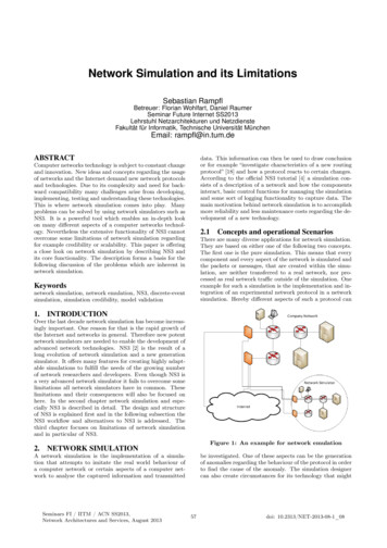
Fard and Sarjoughianstudy in Sacramento, California, over the period 1980 to 2001 with weekly time-step was undertaken onfour climate scenarios to represent the impact of future temperature and precipitation extremes (Dale et al.2015). In another study, the WEAP and LEAP were used for Xiamen, China, to define eleven futurescenarios designed to explore the impacts of different factors on the urban WEN model from both supplyand demand sides (Lin et al. 2019).The Phoenix Active Management Area is a subject study area for understanding the WEN model. The waterand energy systems serve as both demand and supply. A study of the WEN for the Phoenix AMA is carriedout (Mounir, Mascaro, and White 2019; Guan et al. 2020) using the internally linked WEAP and LEAPtools. The models defined for the Phoenix AMA have 119 and 291 different entities. Also, there are nineinterconnections from the energy system to the water system and 172 interconnections from the watersystem to the energy system. A WEN model has been developed using the Algorithmic-IM for the PhoenixAMA (Fard et al. 2020). It replicates the same nexus which was developed using the WEAP-LEAP InternalLinkage. The Algorithmic-IM model for the Phoenix AMA consists of 2 modules and 89 transformations.The computational cost of the Algorithmic-IM is approximately twice that of the WEAP-LEAP InternalLinkage. Furthermore, the DEVS-IM has a theoretical modeling foundation while also having a similarcomputational performance as the Algorithmic-IM (cf. Section 4.3 in (Fard et al. 2020)). The findingsdescribed in this paper show the formal system-theoretic modeling approach is advantageous, for example,in model verification.4PHOENIX AMA WATER-ENERGY NEXUS MODELING VIA DEVS-IMFigure 1 presents the main steps to model and simulate water-energy nexus systems using the DEVS-IMframework. First, the structure of the interaction model must be defined. Second, code is generated for theskeleton of a complete project in the DEVS-Suite simulator. Third, the behavior of the interaction model isdefined by identifying the external connectors and the data transformations under sequential andsynchronous control schemes. Forth, the DEVS-Suite simulator is used to test, debug, and run theinteraction model. This section describes the developed Phoenix AMA model using the DEVS-IMframework (Fard and Sarjoughian 2021b).Figure 1: Steps of developing a model in the DEVS-IM Framework.In the first step, the DEVS-IM REST APIs are used to define the structure of the Phoenix AMA WaterEnergy model (via around 2,000 APIs). This DEVS-IM has two interfaces for the entities belonging to theComponentized WEAP and Componentized LEAP systems. The interfaces are defined using 181Component and 144 Function elements (see Section 2.4). The interaction model has 15 Process, 91 Task,and 201 Connector elements. The interaction model has around 307 atomic and coupled DEVS modelswith 942 ports and 740 couplings. This interaction model replicates the same WEN model developed usingthe WEAP-LEAP Internal Linkage (same as the developed model using the Algorithmic-IM framework).The DEVS-IM model structure is verified for correctness before storing it in MongoDB.In the second step, the skeleton of the DEVS-Suite Simulator project is created using the stored data in theMongoDB database (see Figure 2.a). A package with the same name as the DEVS-IM project (calledProject) is added under the InteractionModel package (which is under the Models package). The root ofthe interaction model (a coupled DEVS model) is implemented using Java with the same name as theDEVS-IM project and a package (DEVS-IM project’s name Models) for the sub-models (i.e., Project.java
Fard and Sarjoughianfile and ProjectModels package). The same approach is applied to implement the Process entities of theinteraction model (i.e., Coupled.java file and CoupledModels package). Also, all Task entities of theinteraction model are implemented using Java (i.e., Atomic.java file). This approach is used for the wholehierarchy of the interaction model. Likewise, each external system is implemented using Java with the samename as the external system and a package (external system’s name Components) for its sub-components(i.e., System.java file and SystemComponents package). Each component is implemented using Java andtwo packages for its sub-components and functions (i.e., Entity.java file and EntityComponents andEntityFunctions packages). This approach is also used to define an interface for the WEAP or LEAPsystems. Figure 2.b presents a portion of the generated files and packages for the DEVS-IM model in theDEVS-Suite Simulator. The “PhoenixAMA.java” file and “PhoenixAMAModels” package contain therequired files to model the interaction model. Also, the “WEAP.java” and “LEAP.java” files and“WEAPComponents” and “LEAPComponents” packages contain the required files to define the interfacesfor the WEAP and LEAP systems.In Figure 2, the “core” package under the “InteractionModel” package contains the main classes for theelements of the DEVS-IM model (Fard and Sarjoughian 2021b). Default behaviors are defined for the InputConnector and Output Connector elements. Each Output Connector of the interaction model is connectedto at least one Function of the external systems. The modeler must define the functionality of the Functionelements in the external systems. For example, the modeler must define how the “setFlow” mponents/DemandsComponents/Power PlantFunction/setFlow.java in Figure 2.b) calls the “ s/Monthly%20Demand/Current%20Accounts” API from the Componentized WEAP framework towrite data to the “Monthly Demand” input variable of the ”Power Plant“ demand site in the “CurrentAccounts” scenario of the Phoenix AMA model in the WEAP system.(a) Folder structure schema(b) The Phoenix AMA DEVS-IM modelFigure 2: DEVS-Suite Simulator generated project via DEVS-IM framework.Having an interface for the external system increases the model complexity, but it has two main advantages.First, it promotes the interaction model to define the external system at different levels of abstraction orignore some parts of the actual model. Second, it helps to have a high level of modularity between how to
Fard and Sarjoughianget data from the external systems and how the interaction model is manipulating the sent/received data.As an example, the Phoenix AMA WEAP model has six demand-site entities, but just one of them is usedinside the Phoenix AMA DEVS-IM model (presented via DemandsComponents/Power Plant.java in Figure 2.b).Figure 3 shows a portion of the Phoenix AMA DEVS-IM model in the DEVS-Suite Simulator’s SimViewwhich hides the sub-models of some coupled models (presented in black-box mode). For example, the submodels of the “Municipal CAP” and “Municipal SRP” coupled models are hidden in Figure 3. The blackbox mode in the DEVS-Suite Simulator allows hierarchical viewing of large-scale models. The white-boxmode (shown for “Municipal Groundwater” coupled model in Figure 3) presents one level of the hierarchyfor the coupled models. This viewing mode is for developing and debugging complex models via step-bystep tracking of the input and output messages among models and monitoring the states of atomic models.Figure 3: Hierarchical WEAP-LEAP Portion of the Phoenix AMA DEVS-IM model depicted in theDEVS-Suite Simulator’s SimView.Figure 4 presents another portion of the DEVS-IM model in the DEVS-Suite Simulator. The outputconnectors are connected to the Componentized WEAP and Componentized LEAP systems. The purplemodels are used to control the execution, and the gray models are used for time-based data transformations.Applying the data transformation to the received data from the external systems must be defined by themodeler via adding behavior to the Task elements (the Atomic models in the DEVS-Suite Simulator). Also,the execution control for the whole interaction model must be defined in a Task element named “Control”.The “Control” model defines the ordering of receiving/sending data from/to the external systems and theorder of executing the WEAP and LEAP systems. As shown in Figure 4, the “Control” model has fiveinputs (“start”, “LEAP Executed”, “LEAP Input Applied”, “WEAP Executed”, and “WEAP InputApplied”) and four outputs (“Get LEAP Data”, “Get WEAP Data”, “Run LEAP”, and “Run WEAP”). The“Control” model replicates the execution of the WEAP and LEAP systems via the WEAP-LEAP InternalLinkage.Figure 5 presents a state machine for the “Control” protocol of the Phoenix AMA DEVS-IM model.Initially, two “WEAPAppliedCount“ and “LEAPAppliedCount“ variables (indicate the number of write dataon the WEAP and LEAP systems) are set to zero, and the state is changed to “Idle”. By receiving a messageon the “start“ input port, a message will be sent on the “runWEAP“ output port, and the state will be changedto “Running WEAP”. As shown in Figure 4, the message will be sent to the “Execute WEAP” outputconnector, which calls an API from the Componentized WEAP framework to run the WEAP simulation.After completing the execution, a message will be sent on the “out” output port of the “Execute WEAP”output connector. This message will be transferred to the “WEAP-Executed” input connector and then willbe transferred to the “WEAP Executed” input port of the “Control” model.
Fard and SarjoughianFigure 4: A portion of the Phoenix AMA DEVS-IM model shown in the DEVS-Suite Simulator.As shown in Figure 5, the arrived message changes the state from the “Running WEAP” to the “GettingWEAP Data”, and a message is sent on the “Get WEAP Data“ output port. The output message will be sentto the output connectors to get data from the WEAP system (by calling the corresponding APIs from theComponentized WEAP framework). The received data from the WEAP system will be sent to the inputconnectors and then to a Task element to apply data transformation (e.g., the “Flow Electricity” in Figure4). After that, the transformed data will be sent to an output connector to send it to the LEAP system viacalling a proper API from the Componentized LEAP framework. Then, the output connector sends anacknowledgment of applying data which will receive on the “LEAP Input Applied” input port of the“Control” model. The “LEAPAppliedCount” variable in Figure 5 increments one unit by receiving thismessage and checks the variable’s value. The state will not change if the variable’s value is less than thetotal number of write processes that must be applied to the LEAP system (the value 88 in Figure 5).Otherwise, the state will be changed to “Running LEAP” and the “LEAPAppliedCount” variable sets tozero. The same scenario happens for running the LEAP system, getting data from the LEAP system, andapplying the transformed data to the WEAP system (see Figure 4 and Figure 5).Figure 5: A state machine for the Control task element of the Phoenix AMA DEVS-IM model.5EVALUATIONVerification is the process of determining that a model implementation and its associated data accuratelyrepresent the developer’s conceptual description and specifications (answering the question “Have we builtthe model, right?”). Validation is the process of determining the degree to which a simulation model and
Fard and Sarjoughianits associated data accurately represent the real world from the perspective of the intended uses of the model(answering the question “Have we built the right model?”). As mentioned in Section 4, the structure of thedefined model is verified during the modeling process using the DEVS-IM framework.5.1 Model ValidationThe developed DEVS-IM Phoenix-AM model, described in Section 4, is converted from the correspondingAlgorithmic-IM model (Fard et al. 2020). Moreover, both Algorithmic-IM and DEVS-IM models arereplications of the Phoenix AMA model developed by domain experts using the WEAP-LEAP InternalLinkage (Guan et al. 2020; Mounir, Mascaro, and White 2019). Figure 6 illustrates the parts and theirrelationships for the Internal Linkage and Interaction Model. The 𝑅𝑒𝑎𝑑(𝑥) on the arrows between thesystems means reading the 𝑥 variable from the source system. Also, the 𝑊𝑟𝑖𝑡𝑒(𝑥, 𝑦) means writing thevalues of the variable 𝑥 (from the source system) to the 𝑦 variable (from the target system). The 𝑊𝑉 and𝐿𝑉 in the formulas represent the WEAP Variables and LEAP Variables, respectively. In the WEAP-LEAPInternal Linkage (see Figure 6.a), the value of a WEAP/LEAP variable drives from some function(s) of theWEAP variables, some function(s) of the LEAP variable, and some constants. As an example, the valuesof the 𝑊𝑉𝑖 calculated by reading the 𝐿𝑉𝑝 variable from the LEAP system, reading the 𝑊𝑉𝑜 variable fromthe WEAP system, and constant coefficient values (i.e., 𝑐1 , 𝑐2 , and 𝑐3 ).(a) WEAP-LEAP Internal Linkage(b) Interaction ModelFigure 6: Comparing the WEAP-LEAP Internal Linkage and Interaction Model.In the Interaction Model approach (Figure 6.b), the data transformation formulas can be completely orpartially applied to the data in the interaction model. For example, the computation formulas for the 𝑊𝑉𝑖in Figure 6.b applied completely, and the computation formulas for the 𝑊𝑉𝑗 applied partially to the data inthe Interaction Model. Completely applying data transformation to the Interaction Model formalizes andreduces the complexity of the relationship between the WEAP and LEAP models. In the WEAP-LEAPInternal Linkage, the systems are responsible for reading the required data from the other system andapplying the data transformation before starting the execution (the 𝑅𝑒𝑎𝑑(𝑥) on the arrows between thesystem in Figure 6.a). Whereas, in our approach, the Interaction Model is responsible for reading the datafrom the system, performing data transformations, writing the transformed data to the system, andcontrolling the execution of the componentized WEAP and LEAP systems (i.e., manage the 𝑅𝑒𝑎𝑑(𝑥) and𝑊𝑟𝑖𝑡𝑒(𝑥, 𝑦) operations for time-driven data transformations shown in Figure 6.b).A variety of methods are used to validate simulation models; for example, “Face Validity”, “HistoricalData Validation”, “Sensitivity Analysis”, etc. (Law 2019). The validation in this research is based on the
Fard and Sarjoughian“Comparison to Other Models” method. The WEAP-LEAP Internal Linkage model is considered to be thereal-world data for validating the DEVS-IM model. The initial states of the Phoenix AMA model in theWEAP and LEAP systems are the same as those in the WEAP-LEAP Internal Linkage and DEVS-IMmodels. The water and energy Phoenix AMA systems are defined as deterministic mass-balance equations.Given the same WEAP and LEAP models with the same initial states, the transformation formulas definedin the Interaction Model should have the same results as those of the internal linkage.The results of executing the Phoenix AMA DEVS-IM model are validated in two scenarios. First, theWEAP model is executed (considering zeros for the dependent variables to the LEAP system), its resultsare read, and the transformed data are applied to the LEAP model (see Figure 5). Then, the LEAP systemis executed (using the applied data by the Interaction Model), its results are read, and the transformed dataare applied to the WEAP model. At this step, the results of both WEAP-LEAP Internal Linkage and DEVSIM approaches are exported to CSV files. Then, a separate application (written in Java programminglanguage) compares the results based on the components, variables, years, and time steps. The outcomeshows that the results are identical in most cases. In some cases, the results have negligible differences( 10-6) due to the transferred data precision and computation/rounding mechanism. The WEAP and LEAPAPIs allow extracting the data from their systems up to 15 digits (maximum six decimal places). However,their computation engines may use data with higher precision. Second, the same mechanism, but firstrunning the LEAP system and then the WEAP system, is applied. Consequently, simulating the WEN modelvia the WEAP-LEAP Internal Linkage and the DEVS-IM have nearly identical results.5.2 Performance EvaluationThe stages in their execution cycles are examined in detail to show the different modeling approachesdescribed in the previous sections. Table 1, Table 2, and Figure 7 present the allocated time and their orderfor different execution steps for one round of simulating the Phoenix AMA model using three simulationapproaches. In the WEAP-LEAP Internal Linkage, the WEAP and LEAP systems are running alternatively(the WEAP system runs first in this experiment). As shown in Table 1, the execution time of each systemincludes reading the required data (interconnection between the systems) from the other system (the amountis not distinguishable from the outside), applying the data transformations, then computing the results. Asshown in Figure 7, the total time for an execution cycle for the WEAP-LEAP Internal Linkage is δt w δt l . The periods for the water and energy models to read the data from one another are δt wr and δt lr (0 δt wr δt w and 0 δt lr δt l ). For one complete simulation round, the WEAP system first reads theLEAP data; then, the water model executes. Next, the LEAP system first reads the WEAP data, and thenthe energy model executes (see Figure 7). The execution time of the Phoenix AMA model using the WEAPLEAP Internal Linkage is 394.5 seconds, with around 19% and 81% of computation time consumed by theWEAP and LEAP systems, respectively.Table 1: Phoenix AMA model time allocation for one round using WEAP-LEAP Internal Linkage.76.1Read Datafrom LEAPApply DataTransformation318.4Quartile3WEAP-LEAPInternal LinkageApply DataTransformationQuartile1Read Datafrom WEAPLEAP ExecutionTotalWEAP Execution394.5389.4395.7The numbers in Table 1 and Table 2 are the average of 10 different runs presented in the second unit. Thelast three columns show the center (median) and the spread of the data (Quartile 1 and Quartile 2). Thesame experiment has been performed for the same Phoenix AMA model (for the internal linkage andAlgorithmic-IM) using older versions of the WEAP and LEAP system (Fard et al. 2020), which results indifferent execution times.As mentioned before, the defined Phoenix AMA mo
ANNSIM'22, July 18-20, San Diego, CA, USA; 2022 Society for Modeling & Simulation . Hessam S. Sarjoughian Arizona Center for Integrative Modeling & Simulation School of Computing and Augmented Intelligence Arizona State University Tempe, AZ, USA ABSTRACT It is beneficial to combine simulation models via I/O data exchanges. The Knowledge .