Transcription
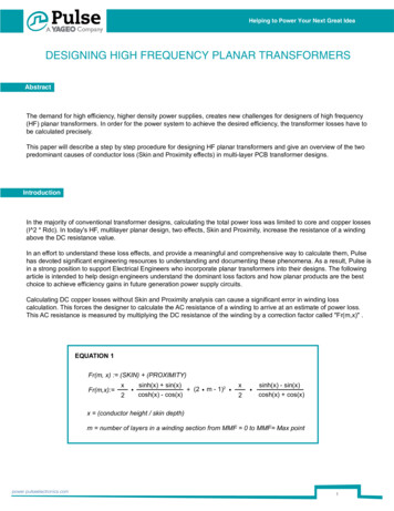
Helping to Power Your Next Great IdeaDESIGNING HIGH FREQUENCY PLANAR TRANSFORMERSAbstractThe demand for high efficiency, higher density power supplies, creates new challenges for designers of high frequency(HF) planar transformers. In order for the power system to achieve the desired efficiency, the transformer losses have tobe calculated precisely.This paper will describe a step by step procedure for designing HF planar transformers and give an overview of the twopredominant causes of conductor loss (Skin and Proximity effects) in multi-layer PCB transformer designs.IntroductionIn the majority of conventional transformer designs, calculating the total power loss was limited to core and copper losses(I 2 * Rdc). In today's HF, multilayer planar design, two effects, Skin and Proximity, increase the resistance of a windingabove the DC resistance value.In an effort to understand these loss effects, and provide a meaningful and comprehensive way to calculate them, Pulsehas devoted significant engineering resources to understanding and documenting these phenomena. As a result, Pulse isin a strong position to support Electrical Engineers who incorporate planar transformers into their designs. The followingarticle is intended to help design engineers understand the dominant loss factors and how planar products are the bestchoice to achieve efficiency gains in future generation power supply circuits.Calculating DC copper losses without Skin and Proximity analysis can cause a significant error in winding losscalculation. This forces the designer to calculate the AC resistance of a winding to arrive at an estimate of power loss.This AC resistance is measured by multiplying the DC resistance of the winding by a correction factor called "Fr(m,x)" .EQUATION 1Fr(m, x) : (SKIN) (PROXIMITY)Fr(m,x): x2sinh(x) sin(x) (2cosh(x) - cos(x)m - 1)2x2sinh(x) - sin(x)cosh(x) cos(x)x (conductor height / skin depth)m number of layers in a winding section from MMF 0 to MMF Max pointpower.pulseelectronics.com1
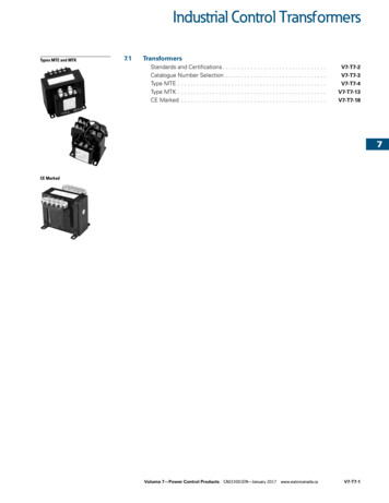
Skin and Proximity generate most HF conductor losses, the Proximity effect being the foremost cause in multi-layertransformer designs. Effective design requires an understanding of these effects and their interactions.Figures 1- 7 illustrate the necessary steps in the design process.Figure 1 illustrates two conductors (C1 andC2) carrying currents in opposite directions(I1 and I2) with their internal (B1 and B3)and external (B2 and B4) generated fields.FIGURE 1Figure 2 concentrates on the effect of the internal generated field (B1) and ignores the external field (B2). A positive signmeans the internal field (B1) is entering the conductor and a negative sign means the field is exiting the conductorsurface. The circles around the positive and negative signs show the generated eddy currents and their correspondingdirections.Notice the addition of eddy currents and I1 on the surfaces of conductor C1 and their reduction in the center. Thisphenomenon causes a change in the distribution of the current density throughout the diameter of conductor C1,resulting in a higher current distribution on the surfaces.Next, analyze the effect of the external field (B2) in C1 on conductor C2. For simplicity assume conductor C2 is notcarrying any of its own current.FIGURE 2power.pulseelectronics.com2
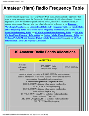
FIGURE 3Figure 3 shows that even if conductor C2 is not carrying any of its own current, it will have an induced eddy currentcaused by the external field of another conductor (C1). An example of this type of conductor is a shield around atransformer.FIGURE 5FIGURE 4Figure 4 reveals the distribution of the current inC2 caused by its own current (I2) and the currentgenerated by the external field of anotherconductor (C1).Figure 5 illustrates a significant effect: the currentin C2 redistributes itself on only one side,which increases the AC resistance of the winding.Figure 6 shows the effect of two conductors in close Proximity. Thiscauses the current to concentrate only on the two adjacent sides. TheProximity effect is often the primary cause of winding loss in highfrequency multi-layer transformer design.power.pulseelectronics.comFIGURE 63
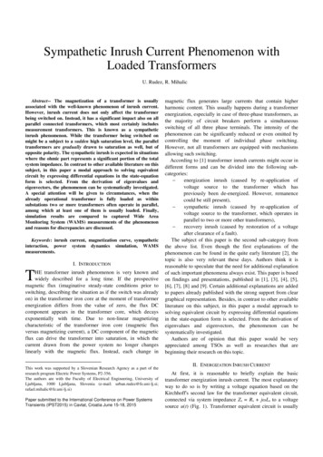
FIGURE 7Figure 7 represents two conductors with current flowing in the same direction. Now that we are familiar with Skin andProximity effects, we can return to Equation 1 and define the variables "x " & "m".EQUATION 1Fr(m, x) : (SKIN) (PROXIMITY)Fr(m,x): x2sinh(x) sin(x) (2cosh(x) - cos(x)m - 1)2x2sinh(x) - sin(x)cosh(x) cos(x)x (conductor height / skin depth)m number of layers in a winding section from MMF 0 to MMF Max pointHOW TO FIND “X” IN EQUATIONx (ConductorHeight / SkinDepth)Conductor’s height for a 2 oz. copper conductorThk : .00007112mmSkin depth for copper @70 Cs: 2.276FreqThis calculation shows that as frequency increases, it reduces the skin depth. So in order to find the skin depth atany harmonic (n), frequency can be replaced with: (n · Frequency)power.pulseelectronics.com4
Using this in EQUATION 1, we can find the AC resistance {Fr[m, X (n)]} for any harmonics.Now we must be able to calculate the AC resistance for any number of layers. Before doing that, “m” in EQUATION 1must be defined.HOW TO FIND “M” IN EQUATIONM Number of layers in a winding section from MMF 0 to MMF Maximum pointTo calculate power loss and leakage inductance, it is essential to know the field intensitybetween layers in a winding section. We can use a spreadsheet application to find theoptimum layer arrangement graphically. Keep in mind that the leakage energy is the energystored between layers, which is a function of H 2 so interleaving reduces the field gradient(H ) between each layer and causes a reduction in leakage inductance.EXAMPLE 1Pri 10TSec 1TLayer arrangement: Sec-Pri-Pri-Pri-Pri-Pri-Pri-Pri-Pri-Pri-Pri-Secmp No. of layers in the Pri winding section from zero to maximum MMF pointms No. of layers in the Sec winding section from zero to maximum MMF pointpower.pulseelectronics.commp 5ms 15
EXAMPLE 2Pri 8TSec 4TLayer arrangement: Sec-Pri-Pri-Pri-Pri-Sec-Sec-Pri-Pri-Pri-Pri-Secmp No. of layers in the Pri winding section from zero to maximum MMF pointms No. of layers in the Sec winding section from zero to maximum MMF pointpower.pulseelectronics.commp 2ms 16
Knowing the AC resistance and the current at each harmonic, the power loss for each harmonic can becalculated.Since we have a PWM square waveform with a given period (T) and Duty (D) the formula below can be applied tocome up with a Fourier series equivalent of the current waveform:power.pulseelectronics.com7
Since it is possible to calculate the correctionfactor (EQUATION 1) and the current for anyharmonic (EQUATION 2), the total AC powerloss for any given number of harmonics can becalculated by summation of power losses ateach harmonic:After calculating DC loss caused by the RMS current, DC resistance of the windings and the core loss, thetransformer's total loss is represented by the summation of all three calculated losses.Total transformer power loss is then:EQUATION 4PTotal PLossAC PLossDC Core lossConclusion1. Skin effect causes current to go to the surface of a conductor and Skin depth is inversely proportional tosquare root of frequency.2. Proximity effect causes the current to flow ONLY on surfaces closest to each other.3. In multilayer PCB transformers, losses in the inner layers can be an order of magnitude higher than on theouter layers. Therefore the innermost layers need to be the thinnest.4. More interleaving causes a reduction in leakage inductance and better regulation with a penalty of higherintrawinding capacitance.Written by: Majid Dadafsharpower.pulseelectronics.com Copyright 2012, Pulse Engineering Inc. Subject to change without notice. All rights reserved8
As a result, Pulse is in a strong position to support Electrical Engineers who incorporate planar transformers into their designs. The following article is intended to help design engineers understand the dominant loss factors and how planar products are the best choice to achieve eff