Transcription
Antennas & Projects20ANTENNA BASICSvery ham needs at least one antenna, and most hams have built one. This chapter, by ChuckHutchinson, K8CH, covers theory and construction of antennas for most radio amateurs. Hereyou’ll find simple verticals and dipoles, as well as quad and Yagi projects and other antennas thatyou can build and use.The amount of available space should be high on the list of factors to consider when selecting anantenna. Those who live in urban areas often must accept a compromise antenna for the HF bandsbecause a city lot won’t accommodate full-size wire dipoles, end-fed systems or high supporting structures. Other limitations are imposed by the amount of money available for an antenna system (includingsupporting hardware), the number of amateur bands to be worked and local zoning ordinances.Operation objectives also come into play. Do you want to dedicate yourself to serious contesting andDXing? Are you looking for general-purpose operation that will yield short- and long-haul QSOs duringperiods of good propagation? Your answers should result in selecting an antenna that will meet yourneeds. You might want to erect the biggest and best collection of antennas that space and finances willallow. If a modest system is the order of the day, then use whatever is practical and accept the performance that follows. Practically any radiator works well under some propagation conditions, assumingthe radiator is able to accept power and radiate it at some useful angle. Any antenna is a good one if itmeets your needs!In general, the height of the antenna above ground is the most critical factor at the higher end of theHF spectrum, that is from roughly 14 through 30 MHz. This is because the antenna should be clear ofconductive objects such as power lines, phone wires, gutters and the like, plus high enough to have a lowradiation angle. Lower frequency antennas, operating between 2 and 10 MHz, should also be kept wellaway from conductive objects and as high above ground as possible if you want good performance.EAntenna PolarizationMost HF-band antennas are either vertically or horizontally polarized, although circular polarizationis possible, just as it is at VHF and UHF. Polarization is determined by the position of the radiatingelement or wire with respect to the earth. Thus a radiator that is parallel to the earth radiates horizontally,while an antenna at a right angle to the earth (vertical) radiates a vertical wave. If a wire antenna is slantedabove earth, it radiates waves that have both a vertical and a horizontal component.Antennas & Projects20. 1
For best results in line-of-sight communications, antennas at both ends of the circuit should have thesame polarization; cross polarization results in many decibels of signal reduction. It is not essential forboth stations to use the same antenna polarity for ionospheric propagation (sky wave). This is becausethe radiated wave is bent and it tumbles considerably during its travel through the ionosphere. At the farend of the communications path the wave may be horizontal, vertical or somewhere in between at anygiven instant. On multihop transmissions, in which the signal is refracted more than once from theionosophere, and subsequently reflected from the Earth’s surface during its travel, considerable polarization shift will occur. For that reason, the main consideration for a good DX antenna is a low angleof radiation rather than the polarization.Antenna BandwidthThe bandwidth of an antenna refers generally to the range of frequencies over which the antenna canbe used to obtain good performance. The bandwidth is often referenced to some SWR value, such as,“The 2:1 SWR bandwidth is 3.5 to 3.8 MHz.” Popular amateur usage of the term “bandwidth” most oftenrefers to the 2:1 SWR bandwidth. Other specific bandwidth terms are also used, such as the gainbandwidth and the front-to-back ratio bandwidth.For the most part, the lower the operating frequency of a given antenna design, the narrower is thebandwidth. This follows the rule that the bandwidth of a resonant circuit doubles as the frequency ofoperation is doubled, assuming the Q is the same for each case. Therefore, it is often difficult to coverall of the 160 or 80-m band for a particular level of SWR with a dipole antenna. It is important torecognize that SWR bandwidth does not always relate directly to gain bandwidth. Depending on theamount of feed-line loss, an 80-m dipole with a relatively narrow 2:1 SWR bandwidth can still radiatea good signal at each end of the band, provided that an antenna tuner is used to allow the transmitter toload properly. Broadbanding techniques, such as fanning the far ends of a dipole to simulate a conicaltype of dipole, can help broaden the SWR response curve.Current and Voltage DistributionWhen power is fed to an antenna, the current and voltage vary along its length. The current is nearlyzero (a current node) at the ends. The current does not actually reach zero at the current nodes, becauseof capacitance at the antenna ends. Insulators, loops at the antenna ends, and support wires all contributeto this capacitance, which is also called the “end effect.” In the case of a half-wave antenna there is acurrent maximum (a current loop) at the center.The opposite is true of the RF voltage. That is, there is a voltage loop at the ends, and in the case ofa half-wave antenna there is a voltage minimum (node) at the center. The voltage is not zero at its nodebecause of the resistance of the antenna, which consists of both the RF resistance of the wire (ohmic lossresistance) and the radiation resistance. The radiation resistance is the equivalent resistance that woulddissipate the power the antenna radiates, with a current flowing in it equal to the antenna current at acurrent loop (maximum). The loss resistance of a half-wave antenna is ordinarily small, compared withthe radiation resistance, and can usually be neglected for practical purposes.ImpedanceThe impedance at a given point in the antenna is determined by the ratio of the voltage to the currentat that point. For example, if there were 100 V and 1.4 A of RF current at a specified point in an antennaand if they were in phase, the impedance would be approximately 71 Ω.Antenna impedance may be either resistive or complex (that is, containing resistance and reactance).This will depend on whether or not the antenna is resonant at the operating frequency. You need to knowthe impedance in order to match the feeder to the feedpoint. Some operators mistakenly believe that amismatch, however small, is a serious matter. This is not true. The importance of a matched line is20.2Chapter 20
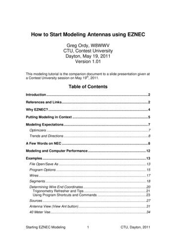
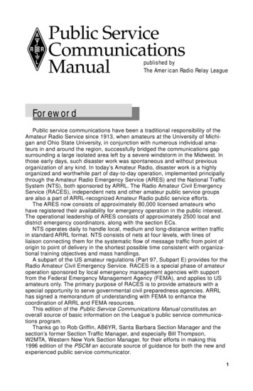
described in detail in the Transmission Lines chapter of this book. The significance of a perfect matchbecomes more pronounced only at VHF and higher, where feed-line losses are a major factor.Some antennas possess a theoretical input impedance at the feedpoint close to that of certain transmission lines. For example, a 0.5-λ (or half-wave) center-fed dipole, placed at a correct height aboveground, will have a feedpoint impedance of approximately 75 Ω. In such a case it is practical to use a75-Ω coaxial or balanced line to feed the antenna. But few amateur half-wave dipoles actually exhibita 75-Ω impedance. This is because at the lower end of the high-frequency spectrum the typical heightabove ground is rarely more than 1/4 λ. The 75-Ω feed-point impedance is most likely to be realized ina practical installation when the horizontal dipole is approximately 1/2, 3/4 or 1 wavelength aboveground. Coax cable having a 50-Ω characteristic impedance is the most common transmission line usedin amateur work.Fig 20.1 shows the difference between the effects of perfectground and typical earth at low antenna heights. The effect ofheight on the radiation resistance of a horizontal half-wave antenna is not drastic so long as the height of the antenna is greaterthan 0.2 λ. Below this height, while decreasing rapidly to zeroover perfectly conducting ground, the resistance decreases lessrapidly with height over actual ground. At lower heights the resistance stops decreasing at around 0.15 λ, and thereafter increasesas height decreases further. The reason for the increasing resistance is that more and more of the induction field of the antennais absorbed by the earth as the height drops below 1/4 λ.Conductor SizeThe impedance of the antenna also depends on the diameter ofthe conductor in relation to the wavelength, as indicated inFig 20.2. If the diameter of the conductor is increased, the capacitance per unit length increases and the inductance per unit lengthdecreases. Since the radiation resistance is affected relativelylittle, the decreased L/C ratio causes the Q of the antenna to decrease so that the resonance curve becomes less sharp with changein frequency. This effect is greater as the diameter is increased,and is a property of some importance at the very high frequencieswhere the wavelength is small.Fig 20.1—Curves showing theradiation resistance of verticaland horizontal half-wavelengthdipoles at various heights aboveground. The broken-line portionof the curve for a horizontaldipole shows the resistance over“average” real earth, the solidline for perfectly conductingground.Directivity and GainAll antennas, even the simplest types, exhibit directive effectsin that the intensity of radiation is not the same in all directionsfrom the antenna. This property of radiating more strongly insome directions than in others is called the directivity of the antenna.The gain of an antenna is closely related to its directivity. Because directivity is based solely on the shape of the directive pattern, it does not take into account any power losses that may occurin an actual antenna system. Gain takes into account those losses.Gain is usually expressed in decibels, and is based on a comparison with a “standard” antenna—usually a dipole or an isotropicradiator. An isotropic radiator is a theoretical antenna that would,Fig 20.2—Effect of antennadiameter on length for halfwavelength resonance, shown asa multiplying factor, K, to beapplied to the free-space, halfwavelength equation.Antennas & Projects20. 3
if placed in the center of an imaginary sphere, evenly illuminate that sphere with radiation. The isotropicradiator is an unambiguous standard, and so is frequently used as the comparison for gain measurements.When the standard is the isotropic radiator in free space, gain is expressed in dBi. When the standard isa dipole, also located in free space, gain is expressed in dBd.The more the directive pattern is compressed—or focused—the greater the power gain of the antenna.This is a result of power being concentrated in some directions at the expense of others. The directivepattern, and therefore the gain, of an antenna at a given frequency is determined by the size and shapeof the antenna, and on its position and orientation relative to the Earth.Elevation AngleFor HF communication, thevertical (elevation) angle ofmaximum radiation is of considerable importance. You will wantto erect your antenna so that itradiates at desirable angles.Tables 20.1, 20.2 and 20.3 showoptimum elevation angles fromlocations in the continental US.These figures are based on statistical averages over all portions ofthe solar sunspot cycle.Since low angles usually aremost effective, this generallymeans that horizontal antennasshould be high—higher is usuallybetter. Experience shows that satisfactory results can be attainedon the bands above 14 MHz withantenna heights between 40 and70 ft. Fig 20.3 shows this effectat work in horizontal dipole antennas.Imperfect GroundEarth conducts, but is far frombeing a perfect conductor. Thisinfluences the radiation patternof the antennas that we use. Theeffect is most pronounced at highvertical angles (the ones thatwe’re least interested in for longdistance communications) forhorizontal antennas. The consequences for vertical antennas aregreatest at low angles, and arequite dramatic as can be clearlyseen in Fig 20.4, where the eleva20.4Chapter 20Table 20.1Optimum Elevation Angles to EuropeBand10 m12 m15 m17 m20 m30 m40 m75 mNortheast5 5 5 4 11 11 15 20 Southeast3 6 7 8 9 11 15 15 UpperMidwest3 4 8 7 8 11 14 15 LowerMidwest7 6 5 5 5 9 14 11 WestCoast3 5 6 5 6 8 12 11 Table 20.2Optimum Elevation Angles to Far EastBand10 m12 m15 m17 m20 m30 m40 m75 mNortheast4 4 7 7 4 7 11 12 Southeast5 8 10 10 10 13 12 14 UpperMidwest5 5 10 9 9 11 12 14 LowerMidwest5 12 10 10 10 12 12 12 WestCoast6 6 8 5 9 9 13 15 Table 20.3Optimum Elevation Angles to South AmericaBand10 m12 m15 m17 m20 m30 m40 m75 mNortheast5 5 5 4 8 8 10 15 Southeast4 5 5 5 8 11 11 15 UpperMidwest4 6 7 5 8 9 9 13 LowerMidwest4 3 4 3 6 9 9 14 WestCoast7 8 8 7 8 9 10 14
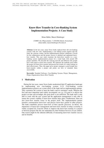
Fig 20.3—Elevation patterns fortwo 40-m dipoles over averageground (conductivity of 5 mS/mand dielectric constant of 13) at1/4 λ (33 ft) and 1/ 2 λ (66 ft)heights. The higher dipole hasa peak gain of 7.1 dBi at anelevation angle of about 26 ,while the lower dipole has moreresponse at high elevationangles.Fig 20.4—Elevation patterns fora vertical dipole over sea watercompared to average ground. Ineach case the center of thedipole is just over 1/ 4 λ high.The low-angle response isgreatly degraded over averageground compared to sea water,which is virtually a perfectground.tion pattern for a 40-m verticalhalf-wave dipole located overaverage ground is compared toone located over saltwater. At10 elevation, the saltwater antenna has about 7 dB more gainthan its landlocked counterpart.A vertical antenna may workwell at HF for a ham living in thearea between Dallas, Texas andLincoln, Nebraska. This area ispastoral, has low hills, and richsoil. Ground of this type has verygood conductivity. By contrast,a ham living in New Hampshire,where the soil is rocky and a poorconductor, may not be satisfiedwith the performance of a vertical HF antenna.Antennas & Projects20. 5
Dipoles and the Half-Wave AntennaA fundamental form of antenna is a wire whose length is half the transmitting wavelength. It is theunit from which many more complex forms of antennas are constructed and is known as a dipole antenna.The length of a half-wave in free space isLength(ft ) 492f (MHz)(1)The actual length of a resonant 1/2-λ antenna will not be exactly equal to the half wavelength in space,but depends on the thickness of the conductor in relation to the wavelength. The relationship is shownin Fig 20.2, where K is a factor that must be multiplied by the half wavelength in free space to obtainthe resonant antenna length. An additional shortening effect occurs with wire antennas supported byinsulators at the ends because of the capacitance added to the system by the insulators (end effect). Thefollowing formula is sufficiently accurate for wire antennas for frequencies up to 30 MHz.Length of half - wave antenna (ft ) 492 0.95468 f (MHz)f (MHz)(2)Example: A half-wave antenna for 7150 kHz (7.15 MHz) is 468/7.15 65.45 ft, or 65 ft 5 inches.Above 30 MHz use the following formulas, particularly for antennas constructed from rod or tubing.K is taken from Fig 20.2.Length of half - wave antenna (ft ) length (in.) 492 Kf (MHz)5904 Kf (MHz)(3)(4)Example: Find the length of a half-wave antenna at 50.1 MHz, if the antenna is made of 1/2-inch-diametertubing. At 50.1 MHz, a half wavelength in space is492 9.82 ft50.1From equation 1 the ratio of half wavelength to conductor diameter (changing wavelength to inches) is(9.82 12) 235.70.5 inchFrom Fig 20.2, K 0.965 for this ratio. The length of the antenna, from equation 3 is492 0.965 9.48 ft50.1or 9 ft 53/4 inches. The answer is obtained directly in inches by substitution in equation 45904 0.965 113.7 inches50.1The length of a half-wave antenna is also affected by the proximity of the dipole ends to nearbyconductive and semiconductive objects. In practice, it is often necessary to do some experimental“pruning” of the wire after cutting the antenna to the computed length, lengthening or shortening it inincrements to obtain a low SWR. When the lowest SWR is obtained for the desired part of an amateurband, the antenna is resonant at that frequency. The value of the SWR indicates the quality of the match20.6Chapter 20
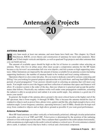
between the antenna and the feed line. If the lowest SWR obtainable is too high for use with solid-staterigs, a Transmatch or line-input matching network may be used, as described in the Transmission Linesand Station Setup chapters.Radiation CharacteristicsThe radiation pattern of a dipole antenna in free space is strongestat right angles to the wire (Fig 20.5). This figure-8 pattern appearsin the real world if the dipole is 1/2 λ or greater above earth and is notdegraded by nearby conductive objects. This assumption is basedalso on a symmetrical feed system. In practice, a coaxial feed linemay distort this pattern slightly, as shown in Fig 20.5. Minimumhorizontal radiation occurs off the ends of the dipole if the antennais parallel to the earth.As an antenna is brought closer to ground, the elevation patternpeaks at a higher elevation angle as shown in Fig 20.3. Fig 20.6illustrates what happens to the directional pattern as antenna heightchanges. Fig 20.6C shows that there is significant radiation off theends of a low horizontal dipole. For the 1/2-λ height (solid line), theradiation off the ends is only 7.6 dB lower than that in the broadsidedirection.Feed MethodsMost amateurs use either coax or open-wire transmission line.Coax is the common choice because it is readily available, its characteristic impedance is close to that of the antenna and it may beeasily routed through or alongwalls and among other cables.The disadvantages of coax are increased RF loss and low workingvoltage (compared to that ofopen-wire line). Both disadvantages make coax a poor choice forhigh-SWR systems.Take care when choosing coax.Use 1/4-inch foam-dielectriccables only for low power (25 Wor less) HF transmissions. Soliddielectric 1/4-inch cables are okayfor 300 W if the SWR is low. Forhigh-power installations, use Fig 20.5—Response of a dipole1/ -inch or larger cables.antenna in free space, where2conductor is along 90 toThe most common two-wire the270 axis, solid line. If thetransmission lines are ladder line currents in the halves of theand twin lead. Since the conduc- dipole are not in phase, slighttors are not shielded, two-wire distortion of the pattern willoccur, broken line. This illuslines are affected by their envi- trates case where balun is notronment. Use standoffs and insu- used on a balanced antenna fedlators to keep the line several with unbalanced line.Fig 20.6—At A, elevation response pattern of a dipoleantenna placed 1/2 λ above aperfectly conducting ground. AtB, the pattern for the sameantenna when raised to onewavelength. For both A and B,the conductor is coming out ofthe paper at right angle. Cshows the azimuth patterns ofthe dipole for the two heights atthe most-favored elevationangle, the solid-line plot for the1/ -λ2 λ height at an elevation angleof 30 , and the broken-line plotλ height at an elevationfor the 1-λangle of 15 . The conductor in Clies along 90 to 270 axis.Antennas & Projects20. 7
inches from structures or other conductors. Ladder line has very low loss (twin lead has a little more),and it can stand very high voltages (SWR) as long as the insulators are clean.Two-wire lines are usually used in balanced systems, so they should have a balun at the transition toan unbalanced transmitter or coax. A Transmatch will be needed to match the line input impedance tothe transmitter.BalunsA balun is a device for feeding a balanced load with an unbalanced line, or vice versa (see theTransmission Lines chapter of this book). Because dipoles are balanced (electrically symmetrical abouttheir feed-points), a balun should be used at the feed-point when a dipole is fed with coax. When coaxfeeds a dipole directly (as in Fig 20.7), current flows on the outsideof the cable shield. The shield can conduct RF onto the transmitterchassis and induce RF onto metal objects near the system. Shieldcurrents can impair the function of instruments connected to the line(such as SWR meters and SWR-protection circuits in the transmitter). The shield current also produces some feed-line radiation,which changes the antenna radiation pattern, and allows objectsnear the cable to affect the antenna-system performance.The consequences may be negligible: A slight skewing of the antenna pattern usually goes unnoticed. Or, they may be significant: False Fig 20.7—Method of affixingSWR readings may cause the transmitter to shut down or destroy the feed line to the center of aoutput transistors; radiating coax near a TV feed line may cause strong dipole antenna. A plastic blockis used as a center insulator.local interference. Therefore, it is better to eliminate feed-line radia- The coax is held in place by ation whenever possible, and a balun should be used at any transitionclamp. A balun is often used tofeed dipoles or other balancedbetween balanced and unbalanced systems. (The Transmission Linesto ensure that thechapter thoroughly describes baluns and their construction.) Even so, antennasradiation pattern is not disbalanced or unbalanced systems without a balun often operate with no torted. See text for explanation.apparent problems. For temporary or emergency stations, do not let thelack of a balun deter you from operating.Practical Dipole AntennasA classic dipole antenna is 1/2-λ long and fed at the center. Thefeed-point impedance is low at the resonant frequency, f0, and oddharmonics thereof. The impedance is high near even harmonics.When fed with coax, a classic dipole provides a reasonably lowSWR at f0 and its odd harmonics.When fed with ladder line (see Fig 20.8A) and a Transmatch, theclassic dipole should be usable near f0 and all harmonic frequencies.(With a wide-range Transmatch, it may work on all frequencies.) Ifthere are problems (such as extremely high SWR or evidence of RFon objects at the operating position), change the feed-line length byadding or subtracting 1/8 λ at the problem frequency. A few suchadjustments should yield a workable solution. Such a system is sometimes called a “center-fed Zepp.” A true “Zepp” antenna is an end-feddipole that is matched by 1/4 λ of open-wire feed line (see Fig 20.8B).The antenna was originally used on zeppelins, with the dipole trailingfrom the feeder, which hung from the airship cabin. It is intended foruse on a single band, but should be usable near odd harmonics of f0.20.8Chapter 20Fig 20.8—Center-fed multiband“Zepp” antenna (A) and an endfed Zepp at (B).
Most dipoles require a little pruning to reach the desired resonant frequency. Here’s a technique tospeed the adjustment.How much to prune: When assembling the antenna, cut the wire 2 to 3% longer than the calculatedlength and record the length. When the antenna is complete, raise it to the working height and check theSWR at several frequencies. Multiply the frequency of the SWR minimum by the antenna length anddivide the result by the desired f0. The result is the finished length; trim both ends equally to reach thatlength and you’re done.Loose ends: Here’s another trick, if you use nonconductive end support lines. When assembling theantenna, mount the end insulators in about 5% from the ends. Raise the antenna and let the ends hangfree. Figure how much to prune and cut it from the hanging ends. If the pruned ends are very long, wrapthem around the insulated line for support.Dipole OrientationDipole antennas need not be installed in a horizontal straight line. They are generally tolerant ofbending, sloping or drooping as required by the antenna site. Remember, however, that dipole antennasare RF conductors. For safety’s sake, mount all antennas away from conductors (especially power lines),combustibles and well beyond the reach of passersby.A sloping dipole is shown in Fig 20.9. This antenna is often usedto favor one direction (the “forward direction” in the figure). Witha nonconducting support and poor earth, signals off the back areweaker than those off the front. With a nonconducting mast and goodearth, the response is omnidirectional. There is no gain in anydirection with a nonconductingmast.A conductive support such as atower acts as a parasitic element.(So does the coax shield, unless itis routed at 90 from the antenna.)The parasitic effects vary withearth quality, support height andother conductors on the support(such as a beam at the top). Withsuch variables, performance isvery difficult to predict.Losses increase as the antenna Fig 20.9—Example of a sloping1ends approach the support or the /2-λλ dipole, or “full sloper.” Onthe lower HF bands, maximumground. To prevent feed-line ra- radiation over poor to averagediation, route the coax away from earth is off the sides and in thethe feed-point at 90 from the an- “forward direction” as indiFig 20.10—At A, details for antenna, and continue on that line cated, if a nonconductivesupport is used. A metal supinverted V fed with open-wireas far as possible.port will alter this pattern byline for multiband HF operation.An Inverted V antenna appears acting as a parasitic element.A Transmatch is shown at B,suitable for matching the anin Fig 20.10. While “V” accu- How it alters the pattern is atenna to the transmitter over arately describes the shape of this complex issue depending onthe electrical height of the mast, wide frequency range. Theantenna, this antenna should not what other antennas are located included angle between the twobe confused with long-wire V on the mast, and on the conlegs should be greater than 90 for best performance.antennas, which are highly direc- figuration of guy wires.Antennas & Projects20. 9
tive. The radiation pattern and dipole impedance depend on the apexangle, and it is very important that the ends do not come too close tolossy ground.Bent dipoles may be used where antenna space is at a premium.Fig 20.11 shows several possibilities; there are many more. Bendingdistorts the radiation pattern somewhat and may affect the impedance as well, but compromises are acceptable when the situationdemands them. When an antenna bends back on itself (as inFig 20.11B) some of the signal is canceled; avoid this if possible.Remember that current produces the radiated signal, and currentis maximum at the dipole center. Therefore, performance is bestwhen the central area of the antenna is straight, high and clear ofnearby objects. Be safe! Keep any bends, sags or hanging ends wellclear of conductors (especially power lines) and combustibles, andbeyond the reach of persons.Multiband DipolesThere are several ways to construct coax-fed multiband dipolesystems. These techniques apply to dipoles of all orientations. Eachmethod requires a little more work than a single dipole, but the materials don’t cost much.Fig 20.11—When limited spaceParallel dipoles are a simple and convenient answer. See Fig 20.12. is available for a dipole anCenter-fed dipoles present low-impedances near f0, or its odd har- tenna, the ends can be bentmonics, and high impedances elsewhere. This lets us construct simple downward as shown at A, oron the radiator as shownmultiband systems that automatically select the appropriate antenna. backat B. The inverted V at C can beConsider a 50-Ω resistor connected in parallel with a 5-kΩ resistor. erected with the ends bentA generator connected across the two resistors will see 49.5 Ω, and parallel with the ground when99% of the current will flow through the 50-Ω resistor. When reso- the available supporting structure is not high enough.nant and nonresonant antennasare parallel connected, thenonresonant antenna takes littlepower and has little effect on thetotal feed-point impedance.Thus, we can connect severalantennas together at the feedpoint, and power naturally flowsto the resonant antenna.There are some limits, however. Wires in close proximitytend to couple and produce mutual inductance. In parallel dipoles, this means that the resonant length of the shorter dipoles Fig 20.12—Multiband antenna using paralleled dipoles, all conΩ coax line. The half-wavelengthens a few percent. Shorter nected to a common 50 or 75-Ωantennas don’t affect longer ones dimensions may be either for the centers of the various bands orselected for favorite frequencies in each band. The length of a halfmuch, so adjust for resonance in wave in feet is 468/frequency in MHz, but because of interactionorder from longest to shortest. among the various elements, some pruning for resonance may beMutual inductance also reduces needed on each band. See text.20.10Chapter 20
the bandwidth of shorter dipoles, so a Transmatch may be needed to achieve an acceptable SWR acrossall bands covered. These effects can be reduced by spreading the ends of the dipoles.Also, the power-distribution mechanism requires that only one of the parallel dipoles is near resonanceon any amateur band. Separate dipoles for 80 and 30 m should not be parallel connected because thehigher band is near an odd harmonic of the lower band (80/3 30) and center-fed dipoles have lowimpedance near odd harmonics. (The 40 and 15-m bands have a similar relationship.) This means thatyou must either accept the lower performance of the low-band antenna operating on a harmonic or erecta separate antenna for those odd-harmonic bands. For example, four parallel-connected dipoles cut for80, 40, 20 and 10 m (fed by a single Transmatch and coaxial cable) work reasonably on all HF bandsfrom 80 through 10 m.Trap dipoles provide multiband operation from a coax-fed single-wire dipole. Fig 20.13 shows a twoband trap antenna. A trap is a parallel-resonant circuit that effectively disconnects wire beyond the trapat the resonant frequency. Traps may be constructed from coiled sections of coax or from discrete LCcomponents.
Antennas & Projects 20.3 described in detail in the Transmission Lines chapter of this book. The significance of a perfect match becomes more pronounced only at VHF and higher, where feed-line losses are a major factor. Some antennas possess a theoretical input impedance at th