Transcription
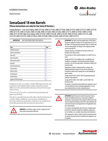
Installation InstructionsOriginal InstructionsSensaGuard 18 mm Barrels(These instructions are only for the Series B Version.)Catalog Numbers—Low-level Coding: 440N-Z21S16A, 440N-Z21S16B, 440N-Z21S16H, 440N-Z21S16J, 440N-Z21S17A, 440N-Z21S17B,440N-Z21S17H, 440N-Z21S26A, 440N-Z21S26B, 440N-Z21S26H, 440N-Z21S26J, 440N-Z21S17J, 440N-Z21X16H, 440N-Z21S16E,440N-Z21S17B-PUR, High-level Coding: 440N-Z21U16A, 440N-Z21U16B, 440N-Z21U16H, 440N-Z21U16J, 440N-Z21U17A, 440NZ21U17B, 440N-Z21U17H, 440N-Z21U26A, 440N-Z21U26B, 440N-Z21U26H, 440N-Z21U26J, 440N-Z21U17JIMPORTANTSAVE THESE INSTRUCTIONS FOR FUTURE USE.TopicPageAdditional Resources2Technical Specifications2Dimensions2Mode of Operation3Mounting Information3Diagnostic3Typical Wiring Diagram4Commissioning4OSSD Test Pulses5Timing Diagram6Troubleshooting7Application Wiring Examples8Installation must be in accordance with the following instructions andspecifications and implemented by suitable competent personnel.Adherence to the recommended maintenance instructions forms partof the warranty.This unit is not to be used as a mechanical stop. Guard stops andguides must be fitted.This device is intended to be part of the safety-related control system ofa machine. Before installation, a risk assessment is performed todetermine whether the specifications of this device are suitable for allforeseeable operational and environmental characteristics.WARNING: Do not defeat, tamper, remove, or bypass this unit.Severe injury to personnel could result.ATTENTION: This device must be provided with a 24V DC PELV orSELV power supply that conforms to the requirements of 414-3 ofIEC 60364-4-41 where provisions have been taken. To confirm that,even if an internal fault, the voltage at the outgoing terminalscannot exceed 60V DC.Improper selection or installation of the devices affects theintegrity of the safety systems.Personal injury or death, property damage, or economic loss canresult.Comply with ISO 14119 including section, accessibility to theinstallation, arrangement, and mounting, possible substituteactuation, access to the escape release, motivation to defeat, andactuation mode.Management controls, working procedures, training, andadditional protective measures can be used to minimize themotivation to defeat and to manage the use and availability ofspare actuators.Comply with ISO 13857 and ISO 13855 for guard openings andminimum (safe) distances.Comply with IEC 62061 or ISO 13849-1 and ISO 13849-2 forfunctional safety.This product is intended for industrial/business application only. Itis not intended to be used in residential applications as it maycause radio interference on other residential devices.ATTENTION: Read this document and the documents that arelisted in the Additional Resources section about installation,configuration, and operation of this equipment before you install.Users are required to familiarize themselves with installation andconnection instructions and requirements of all applicable codes,laws, and standards.In accordance with applicable codes of practice, suitably trainedpersonnel are required to implement installation, adjustments,service initiation, use, assembly, disassembly, and maintenanceIf this equipment is used in a manner that the manufacturer doesnot specify, the protection that is provided by the equipment canbe impaired.
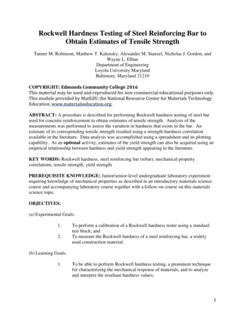
SensaGuard 18 mm BarrelsAdditional ResourcesResourceDescriptionProvides general guidelines forIndustrial Automation Wiring and Grounding Guidelines,installing a Rockwell Automation publication 1770-4.1industrial system.Product Certifications website, cationProvides declarations of conformity,certificates, and other certificationdetails.You can view or download publications (including translations) athttp://www.rockwellautomation.com/literature/. To order papercopies of technical documentation, contact your local Allen-Bradleydistributor or Rockwell Automation sales representative.ATTENTION: Do not attempt to install this device unless theinstallation instructions have been studied and understood. Thisdocument acts as a guide for a typical installation and is availablein additional languages at e 1 - Technical SpecificationsAttribute18 mm PlasticActuatorAttribute18 mm PlasticActuator30 mm PlasticActuator18 mm StainlessSteel ActuatorIEC 60947-5-3, Cat. 4 PLe Per ISO 13849-1, Type 4 Interlocking Deviceaccording to ISO 14119 with either low (standard) or high (unique)coding, SIL CL3 per IEC 62061 and IEC 61508Functional safety dataPFHD 1.32E-9 (Probability of dangerous failure per hour)T1 20 (Proof test interval)CertificationsCE marked for all applicable directives, c-UL-us (UL 508), and n/overview.pageStandardsSafety ClassificationIEC 60947-5-3, Cat. 4 PLe Per ISO 13849-1, Type 4 Interlocking Deviceaccording to ISO 14119 with either low (standard) or high (unique)coding, SIL CL3 per IEC 62061 and IEC 61508Pollution degreeIEC 60947-1 — 3Electro-magnetic Compatibility (EMC)IEC 61000-4-2: air dischargePer IEC 61326-1 (functional): 8 kVPer IEC 61000-6-7 (fail-safe): 8 kVElectrostatic discharge ESDIEC 61000-4-2: contact dischargePer IEC 61326-1 (functional): 4 kVPer IEC 61000-6-7 (fail-safe): 6 kVRadiated EMF immunityIEC 61000-4-3Per IEC 61326-1 (functional): 10 V/mPer IEC 61000-6-7 (fail-safe): 20 V/mElectrical fast transient/burstimmunityIEC 61000-4-4Per IEC 61326-1 (functional): 2 kV/5 kHzPer IEC 61000-6-7 (fail-safe): 2 kV/5 kHzConducted immunityIEC 61000-4-6Per IEC 61326-1 (functional): 10VPer IEC 61000-6-7 (fail-safe): 20VRated impulse withstand voltageIEC 60947-1: 1 kVProtectionShort circuit, overload, reverse polarity, overvoltage, loss of groundFigure 1 - 18 mm Plastic Barrel Dimensions [mm 8.92(1.94) 19.81(0.78)30 mm ActuatorOperating Characteristics4.57 (0.18) dia.2 places19.81(0.78)22.22(0.87)48.92 (1.94)Sensing distance, assured ON15 mm (0.59 in.)25 mm (0.98 in.)10 mm (0.39 in.)Sensing distance, assured OFF25 mm (0.98 in.)35 mm (1.78 in.)20 mm (0.79 in.)Operating voltage24V DC 10%/-15% Class 2 SELV or PELV power supplyResponse time (Off)45 msUtilization category according toUeleDC-12 and DC-1324V200 mAFrequency of Operating Cycle0.25 HzNo-load supply current 50 mA15.42(0.61)3.17(0.12)36.47(1.44)19.81(0.78)18 mm ActuatorSafe stateDe-energized (2 x PNP, 0V), AUX energized (1 x PNP, 24V)Run stateEnergized (2 x PNP, 24V), AUX de-energized (1 x PNP, 0V)Load current200 mA maximumVoltage drop 1.5VSwitches connected in seriesUnlimited. See Timing Diagram on page 6.13.72(0.54)MechanicalSensor case materialPolycarbonateStainless Steel 304Actuator case materialPolycarbonateStainless Steel 304EnvironmentalOperating temperature-25 70 C (-13 158 F)Operating humidity5 95% relativeWashdown ratingIP66, IP67, IP69KShock and vibrationIEC 60068-2-27 — 30 g (1.05 oz), 11 msIEC 60068-2-6 — 10 55 Hz4.57 (0.18) dia.2 places15.87(0.62)Outputs (OSSD)218 mm StainlessSteel ActuatorSafety RatingsSafety RatingsStandardsSafety Classification30 mm PlasticActuatorRockwell Automation Publication 440N-IN017B-EN-P - April 201915.87(0.62)36.47 (1.44)67.06 (2.64)2.03 (0.08)M18x1Sensor
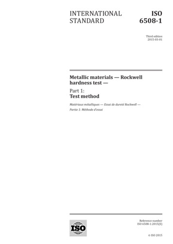
SensaGuard 18 mm BarrelsFigure 2 - 18 mm Stainless Steel Barrel Dimensions [mm (in.)]Figure 4 - Minimum Distance between Sensors [mm (in.)]Stainless Steel Housing14.43(0.57)18 mm Actuator4.57 (0.18) dia.2 places4.75(0.19)40 (1.57)36.47 15.87(1.44) 62)Plastic Housing36.47 (1.44)18 mm Actuator74.8 (2.95)48.2 (1.90)14.5(0.57)44.4 (1.75)SensorSensor230 mm Actuator40 (1.57)Sensor1M18X110.4 (0.41)Figure 3 - Mode of Operation — Status Indicators18 and 30 mmActuator60 (2.36)Sensor2Sensor1Sensor2Figure 5 - Misalignment Curve18 510518 mm PlasticBarrel18 mm StainlessSteel Barrel Actuator is supplied with sensor Indicator green: Door/guard closed, safety outputs active.0-40-30-20-1001020304018 mm Plastic Barrel with 30 mm Actuator18 mm Plastic Barrel with 18 mm Actuator18 mm Stainless Steel Barrel with 18 mm Actuator Indicator red: Door/guard open, safety outputs off. Indicator flashes red: Unit failure. See Diagnostic — UnitIndicators on page 3.Table 2 - Diagnostic — Unit Indicators Indicator flashes green: Safety inputs off.Mounting InformationStatus/DiagnosticIndicatorUse non-removable screws, bolts, or nuts to mount the switch andactuator. Do not over torque the mounting hardware. Position theswitch and actuator so they are aligned with each other.Nut Torque SpecificationSwitch/Actuator: 2.20 N m (19.5 in lbs)StateStatusTroubleshootingOffNot powered—RedOSSD not active—GreenOSSD active—Green flashPower up test or OSSDinputs not validCheck 24V DC or OSSD inputs(yellow or red wire)0.5 Hz flash OSSD faultOSSD fault—check OSSDoutputs are not shorted toGND, 24V DC or each other.2 Hz flash internal faultCycle power.Red flashSee Unique Coded Diagnostic on page 5 for learning sequence errors.Rockwell Automation Publication 440N-IN017B-EN-P - April 20193
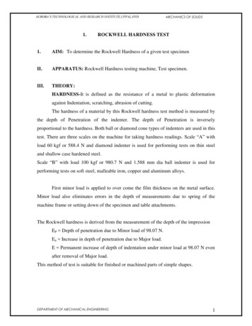
SensaGuard 18 mm BarrelsTypical Wiring DiagramCommissioning (Unique Coded Units) —Power the SensorTable 3 - 8-pin UnitN/A1- 3OSSD 1 Input - 8OSSD 2 Input - 4Connect the sensor to 24V DC (see Typical Wiring Diagram onpage 4 for help).2 - 24V DC1 - Auxiliary Output7 - 0VOSSD 1 Output - 5IMPORTANT6 - OSSD 2 OutputPin NumberWire ColorSignal1WhiteAuxiliary Output2Brown24V DC3Green—14YellowOSSD 2 Input5GrayOSSD 1 Output6PinkOSSD 2 Output7Blue0V8RedOSSD 1 InputThe unique coded sensor is shipped from the factoryunprogrammed and must be taught a unique coded actuator,see Teaching the Actuator (Ability to Learn an AdditionalActuator).A unique coded sensor can only learn a unique coded actuatorand cannot learn a standard coded actuator.A standard coded sensor does not work with a unique codedactuator.The unique coded sensor, “Status/Diag” indicator, begins toblink green eight times then repeats, which indicates that thesensor has not yet learned an actuator.The unique coded sensor can be locked so it cannot learnanother actuator, see Teaching the Unique Actuator (OneTime Learn Only; Unit Locked) on page 5.Recommended mating cable, 2 m (6.5 ft)—889D-F8AB-2. Replacethe 2 with 5 (5 m [16.4 ft]) or 10 (10 m [32.8 ft]) for standard cablelengths.Teaching the Actuator (Ability to Learn an Additional Actuator)1Quick StartShield wire for Stainless Steel version.Table 4 - 5-pin Unit1. Power up the sensor and bring an actuator into the sensing range.2. Leave the actuator in the sensing field for two minutes or longer.253. Learn is complete.13IMPORTANT4Pin NumberColorSignal1Brown 24V2WhiteSafety OSSD 1 Output3Blue0V4BlackSafety OSSD 2 Output5GrayAuxiliary OutputThe recommended cordset is 2 m (6.5 ft) - 889D-F5AC-2. Foradditional lengths, replace the 2 with 5 (5 m [16 ft]) or 10 (10 m [32.8ft]) for standard cable lengths.IMPORTANTIf you do not require the auxiliary signal, a 4-pin cordset(889D-F4AC-2) can be used.The recommended patchcord for use with ArmorBlock Guard SafetyI/O is 2 m (6.5 ft) - 889D-F4ACDM-2. Replace the 2 with 0M3(0.3 m [0.98 ft]), 1 (1 m [3.28 ft]), 5 (5 m [16.4 ft]), or 10 (10 m[32.8 ft]) for standard cable lengths.IMPORTANT4The sensor can learn a new actuator up to eight times. TheStatus/Diag” indicator blinks the number of actuators leftthat a sensor can learn.The sensor automatically starts the learning process as soon as anactuator is brought into the sensing range.Learning Sequence1. Target present“Status/Diag” indicator blinking green2 Hz rate (15 s)2. Verifying actuator“Status/Diag” indicator blinking green/red 1 Hz rate (15 s)3. Program sensor“Status/Diag” indicator blinking green/red 2 Hz rate (15 s)4. Program complete“Status/Diag” indicator blinking green2 Hz rate (# of learns remaining) (15 s)5. Ready state“Status/Diag” indicator solid green6. Learn is completedDo not use a 5-pin patchcord with the ArmorBlock I/O.Rockwell Automation Publication 440N-IN017B-EN-P - April 2019
SensaGuard 18 mm BarrelsTeaching the Unique Actuator (One Time Learn Only;Unit Locked)Initially Teaching in the ActuatorThe sensor automatically starts the learning process as soon as anactuator is brought into the sensing range.Learning Sequence1. Target present“Status/Diag” indicator blinking green2 Hz rate (15 s)2. Verifying actuator“Status/Diag” indicator blinking green/red 1 Hz rate (15 s)3. Program sensor“Status/Diag” indicator blinking green/red 2 Hz rate (15 s)4. Program Locking“Status/Diag” indicator blinking green2 Hz rate (# of learns remaining) (15 s)5. Remove the actuatorfrom the sensing field"Status/Diag" indicator changes to solidred6. Replace the actuator"Status/Diag" indicator continuesback into the sensing field blinking green 2 Hz rate (number oflearns remaining), this action triggers thelock function.7. Ready state“Status/Diag” indicator solid green8. Learn is completedSensor is locked and cannot learnanother actuator.Learning a New Actuator (Unique Coded Actuator Only)To learn a replacement actuator, bring the actuator to be taught intothe sensing range of the safety switch.The learn sequence is the same as the sequence for teaching theactuator (ability to learn an additional actuator).A sensor cannot relearn a previously learned actuator or a standardSensaGuard actuator.Unique Coded DiagnosticError codes for learning process. Power cycle to clear fault.Status/Diag Indicator—Flashes (2 Hz)Error CodeGreenOSSD inputs not validRed-Red-Red-GreenCannot learn a standard SensaGuard actuatorRed-Red-Red-Green-GreenActuator already learnedRed-Red-Red-Green-Green-GreenBad RFID; Target that is moved out of rangeRed-Red-Red-Green-Green-Green-GreenExceeded learning eight nit locked: Cannot learn another actuatorOSSD Test Pulses0450Time (µs)PeriodicityPink WireGray Wire02045Time (ms)Individual PulsesTest pulses appear on each OSSD output. These pulses areapproximately every 45 ms. The times that are shown are approximateand depend on the processing of the safety-related status.The sensor only recognizes the most recently learned actuator.Rockwell Automation Publication 440N-IN017B-EN-P - April 20195
SensaGuard 18 mm BarrelsTiming Diagram 24V DCSensaGuard ActuatorSensaGuard ActuatorSensaGuard ActuatorSensaGuard SensorUnit 1SensaGuard SensorUnit 2SensaGuard SensorUnit 3S11 S12 S52 A113 23 33 21 S22 A2 S34 1424 34 4224V GroundResponse Time: Safety Outputs Turn OFFInitial Conditions: All actuators are in sensing distance.Sensor 1 OSSD outputs (gray andActuator 1 is movedpink) turn OFF. Sensor 1 indicatorout of sensing range.turns solid red.0 ms45msSensor 2 OSSD outputs (gray andpink) turn OFF. Sensor 2 indicatorflashes green.Sensor 3 OSSD outputs (gray andpink) turn OFF. Sensor 3 indicatorflashes green.50 ms55 msResponse Time: Safety Outputs Turn ONInitial Conditions: Actuator1 is out of sensing range. Sensor 1 indicator is solid red. Actuators 2 and 3 are in sensing range. Sensor 2 and 3 indicators flash green.Sensor 2 OSSD inputs (red andSensor 3 OSSD inputs (red andSensor 3 OSSD outputs (gray andyellow) transition to 24V DC fromyellow) transition to 24V DC frompink) are energized.Sensor 1 OSSD outputs. Sensor 1Sensor 2 OSSD outputs. Sensor 2Sensor 3 indicator turns solidindicator turns solid green.indicator turns solid green.green.Actuator 1 is movedinto sensing range.0 ms6360 ms378 msRockwell Automation Publication 440N-IN017B-EN-P - April 2019396 ms
24V GroundPower 24V DCSupply1606-XL120DPower SupplySwitch 1Actuator dYellowPinkGrayBrownRedYellowWhiteActuator 3 is in sensing range.Switch 3 has a fault.See Diagnostic table — redindicator is flashing. 0V 0VBlueActuator 4 is in the sensing range.Switch 4 is functioning properly.OSSD inputs are 0V.OSSDs are de-energized to 0V.Green indicator is flashing toindicate that OSSD inputs are not24V.iteWhSwitch 4Actuator 4PinkGrayBrownRedYellowActuator 2 is in sensing range.Switch 2 is functioning properly.OSSDs are energized to 24V.Green indicator is ON. 24V 24ViteWhSwitch 3Actuator 3BlueOSSDs are OFF. 0V 0VActuator 5 is in the sensing range.Switch 5 is functioning properly.OSSD inputs are 0V.OSSDs are de-energized to 0V.Green indicator is flashing toindicate that OSSD inputs are not24V. 0V 0ViteWhSwitch 5Actuator 5PinkGrayBrownRedYellowActuator 1 is in sensing range.Switch 1 is functioning properly.OSSDs are energized to 24V.Green indicator is ON. 24V 24ViteWhSwitch 2Actuator 2SensaGuard 18 mm BarrelsTroubleshooting — Series CircuitRockwell Automation Publication 440N-IN017B-EN-P - April 20197
SensaGuard 18 mm BarrelsApplication Wiring ExamplesWiring to MSR127 Safety Relay 24V 24VSensor ActuatorSensor ActuatorSensaGuard SensorUnit 1SensaGuard SensorUnit 1S11 S12 S52 A1K1BrownRedYellow13 23 33 41PinkGrayBlueBrownRedYellowPinkGrayBlueS11 S12 S52 A113 23 33 41K1K2MSR127RP440R-N231xxS22 S21 A2 S34 14K124V GroundK2MSR127TP440R-N231xxS22 S21 A2 S34 14Reset24 34 42K224 34 42K124V GroundK2MSR127RP with one sensor, automatic reset, drives 100S or 700S safety relays.MSR127RP with one sensor, monitored manual reset, drives 100S or 700S safety relays. 24V 24VSensor ActuatorSensor ActuatorSensor ActuatorSensor ActuatorSensaGuard SensorUnit 1SensaGuard SensorUnit 2SensaGuard SensorUnit 1SensaGuard SensorUnit yBlue440L GuardShieldReceiver TransmitterBrownBrown12Pink 6Gray5Blue7Green3 Blue3S11 S12 S52 A113 23 33 41S11 S12 S52 A1K113 23 33 41K2MSR127RP440R-N231xxS22 S21 A2 S34 1424V GroundK1K2MSR127RP440R-N231xxS22 S21 A2 S34 14Reset24 34 42K224V GroundMSR127RP with one sensor, monitored manual reset, driving 100S or 700S safetyrelays.IMPORTANT8K1K1Reset24 34 42K2MSR127RP with two sensors and 1 440L light curtain in series, monitored manual reset, driving 100S or700S safety relays.The light curtain must be last (the furthest from MSR127).Rockwell Automation Publication 440N-IN017B-EN-P - April 2019
SensaGuard 18 mm BarrelsGuardmaster SI or DI Safety Relay WiringBrown 24V yBrown889D-F5AC-5WhiteBlueGrayK1S32 S42 S22 S12 A1Logic01238DI47440R-D22R2 6 51323S11 S21 L11 L12 A21424 Y32GateOpenS34K1 K224V GroundK1K2BlackWhiteGray889D-F5AC-5BlueBrown 24V DCResetS11 S21 S22 S12 A1 13 23 S34Reset0AMMMSI440R-S12R2L11A2 14 24 Y3224V GroundGateOpenRockwell Automation Publication 440N-IN017B-EN-P - April 2019K1 K29
SensaGuard 18 mm BarrelsGuardmaster SI or DI Safety Relay *889D-F8AB-*YellowRed 24V DCS12 S22 S32 S42 A10Logic8DI113GateOpenS34237 6 5 4440R-D22R2S11 S21 L11 L12 A2 14GateOpen2324 Y32K1 K224V GroundIMPORTANTThe green wire is connected to the housing of the stainless steelSensaGuard only; it has no connection for plastic SensaGuard. 24V B-*GreenBrownK1ResetS11 S21 S22 S12 A1 13 23 S34Reset0AMMMSI440R-S12R2L11A2 14 24 Y32GateOpen24V Ground10Rockwell Automation Publication 440N-IN017B-EN-P - April 2019K1 K2
SensaGuard 18 mm BarrelsCR30 Software Configurable Relay Wiring 24V DCRedBlue 100 01 02 03 04 05 06 07 08 09 10 11CR30440C-CR30-22BBBA1 A2 12 13 14 15 16 17 18 19 20 21GateOpenGateOpen100S or 700S or 700HPSContactors and RelaysK1K224V GroundRockwell Automation Publication 440N-IN017B-EN-P - April 201911
SensaGuard 18 mm Barrels1734 POINT Guard I/O Wiring 24V ueBrown889D-F8AB-5Green BrownNotConnectedWhite RedBlue t/IP1734-AENTGateOpenGateOpen1734-IB8S100S or 700S or 700HPSContactors and Relays24V Ground12Rockwell Automation Publication 440N-IN017B-EN-P - April 20191734-OB8SK1K2100S or 700S or 700HPSContactors and Relays
SensaGuard 18 mm Barrels1732DS/ES ArmorBlock Guard Safety I/O Wiring1732ES-IB12XOB4Ethernet871A-TS5-DM15-pin Field AB-5CordsetGreenBrownRedYellowX100Not ConnectedPowerX101 T15 T01 T12 I1F 3C4 I05 T01 T12 I13C C4 I05 T01 242 O1G 3C4 O05C1 T12 I13C D4 I05 T01 24 Contactors and Relays2 O1H 3C4 O05C3C BK2871A-TS5-DM1Safety ResetThe screen shots below show the input and outputconfiguration for the 1732ES.24V Ground4X11 T12 I1E 3C4 I05 T0OSSD 4 I0K111 T12 I13C A4 I05 T0OSSD 2 -DM1K2K1100S or 700S or 700HPS43 24V DCRockwell Automation Publication 440N-IN017B-EN-P - April 201913
SensaGuard 18 mm BarrelsNotes:14Rockwell Automation Publication 440N-IN017B-EN-P - April 2019
SensaGuard 18 mm BarrelsNotes:Rockwell Automation Publication 440N-IN017B-EN-P - April 201915
Rockwell Automation SupportUse the following resources to access support information.Technical Support CenterKnowledgebase Articles, How-to Videos, FAQs, Chat, UserForums, and Product Notification cal Technical Support Phone NumbersLocate the phone number for your upport/get-support-now.pageDirect Dial CodesFind the Direct Dial Code for your product. Use the code toroute your call directly to a technical support support/direct-dial.pageLiterature LibraryInstallation Instructions, Manuals, Brochures, andTechnical rature-library/overview.pageProduct Compatibility and DownloadCenter (PCDC)Get help determining how products interact, checkfeatures and capabilities, and find associated support/pcdc.pageDocumentation FeedbackYour comments will help us serve your documentation needs better. If you have any suggestions on how to improve this document, complete theHow Are We Doing? form at s/literature/documents/du/ra-du002 -en-e.pdf.Waste Electrical and Electronic Equipment (WEEE)At the end of life, this equipment should be collected separatelyfrom any unsorted municipal waste.Rockwell Automation maintains current product environmental information on its website nmental-compliance.page.Allen-Bradley, ArmorBlock, Guardmaster, POINT Guard I/O, Rockwell Automation, Rockwell Software, SensaGuard are trademarks of Rockwell Automation, Inc.Trademarks not belonging to Rockwell Automation are property of their respective companies.Rockwell Otomasyon Ticaret A.Ş., Kar Plaza İş Merkezi E Blok Kat:6 34752 İçerenköy, İstanbul, Tel: 90 (216) 5698400Publication 440N-IN017B-EN-P - April 2019Supersedes Publication 440N-IN017A-EN-P - May 2017PN-39201910002550446 Ver 01Copyright 2019 Rockwell Automation, Inc. All rights reserved. Printed in the U.S.A.
IEC 60947-5-3, Cat. 4 PLe Per ISO 13849-1, Type 4 Interlocking Device according to ISO 14119 with either low (standard) or high (unique) coding, SIL CL3 per