Transcription
Replication FlowDEC 2021VMware Cloud Director Availability 4.3
Replication FlowYou can find the most up-to-date technical documentation on the VMware website at:https://docs.vmware.com/VMware, Inc.3401 Hillview Ave.Palo Alto, CA 94304www.vmware.comCopyrightVMware, Inc. 2018-2021 VMware, Inc. All rights reserved. Copyright and trademark information.2
Contents1 About the Issue 42 Replication Process Overview 63 Replication Data Path 134 Connectivity 265 Monitoring 32VMware, Inc.3
About the Issue1Replications experiencing Recovery Point Objective (RPO) violations while the replication traffic isnot using all of the available network bandwidth require optimizing the components configurationin the disaster recovery infrastructure. Shorter target RPO, specially 1-minute, requires thatall replication operations be complete in a shorter time window, raising the chance for RPOviolations.When using VMware Cloud Director Availability the replication traffic might only use asmall part of the available bandwidth while a replication might experience RPO violations. Theresolution is not simple as it is a combination of the way VMware Cloud Director Availabilityoperates and the design and configuration of the virtual infrastructure components. While allreplications are free of RPO violations even when VMware Cloud Director Availability does notuse most of the available bandwidth is not an issue. However, when RPO violations are present,the VMware Cloud Director Availability design and configuration requires investigation. Betweenthe source of a replication and its destination, there are multiple components. The configurationof each component in this long chain might impact the replication flow. When the configurationof some components does not deliver optimal performance, might show issues in the VMwareCloud Director Availability Dashboard page.1-minute RPOVMware Cloud Director Availability 4.3 and later allow configuring replications with RPO as shortas 1-minute. When configuring replications with 1-minute RPO, the chances for multiple concurrentoperations sharply increase and require additional attention to the configuration details. As thesame principles apply for all replications, the information in this document does not limit to1-minute RPO replications only.About the Replication Flow DocumentIn addition to showing each component that participates in the replication flow, this documentalso explores the various configurations of a single component and whether specific settingvalues are optimal or suboptimal. This document provides information for correctly sizingVMware Cloud Director Availability and for optimizing disaster recovery virtual infrastructures.Following correct design decisions helps prevent or reduce the support requests.VMware, Inc.4
Replication FlowIntended AudienceThe Replication Flow document is intended for cloud architects, infrastructure administrators,cloud administrators, and cloud operators using VMware Cloud Director Availability in a disasterrecovery environment that complies with the requirements for capacity, scalability, businesscontinuity, and disaster recovery.VMware software familiarity is required.VMware, Inc.5
Replication Process Overview2VMware Cloud Director Availability replicates workloads to and from on-premises sites and toand from cloud sites. Learn more about the incoming and outgoing replication data paths, theway the replication works, and the replication operations performed in the sites for ensuring thereplications are free from Recovery Point Objective (RPO) violations.Replication Path OverviewDepending on the source and the destination of a replication, for replicating virtual machines andvApps VMware Cloud Director Availability supports the following replications.Cloud-to-cloudReplications between two cloud sites, managed by VMware Cloud Director . In eachVMware Cloud Director site, VMware Cloud Director Availability consists of:na single Cloud Replication Management Appliance running the Manager Service andthe Cloud Service providing the VMware Cloud Director Availability Portal for serviceproviders and for tenants,na single Cloud Tunnel Appliance running the Tunnel Service providing the ServiceEndpoint in the cloud site,nand one or more Cloud Replicator Appliance instances running the Replicator Service, theLightweight Delta Protocol Service (LWD Proxy) and vSphere Replication Service withvSphere Replication filter.Replicating between two cloud sites first requires establishing a pairing between the twoCloud Tunnel Appliance instances in the sites. This allows configuring and performingreplications in both directions.On-premises-to-cloudReplications between VMware vCenter Server -managed infrastructure and a cloud sitemanaged by VMware Cloud Director. These replications require deploying a single VMwareCloud Director Availability On-Premises Appliance in the vSphere infrastructure, potentiallyscalable with multiple on-premises appliance instances for a single vCenter Server instance.VMware, Inc.6
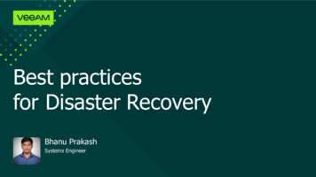
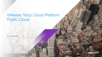
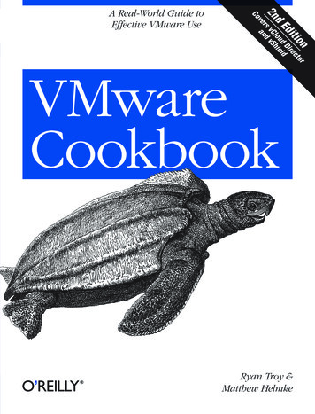
Replication FlowThe on-premises appliance establishes pairing to the Cloud Tunnel Appliance in the cloud site.This allows configuring and performing replications in both directions.Figure 2-1. Replication path between two cloud sites and an on-premises sitePublicNetworkCloud site BCloud site AOn-Premises sitePrivateNetworkCloudTunnel ApplianceCloudTunnel ApplianceCloudReplicator ApplianceCloudReplicator ApplianceVMkernelVMkernelData storeVMware, Inc.VMkernelESXi HostESXi HostVMkernel/HBAVMware Cloud Director AvailabilityOn-Premises ApplianceVMkernel/HBAData storeESXi HostVMkernel/HBAData store7
Replication FlownThis example shows the network connectivity and pairing between the two cloud sites overa private network. Alternatively, the cloud-to-cloud site pairing allows establishing over thepublic Internet.nThis example also shows the connectivity between the cloud site B and the on-premises siteover Internet. Alternatively, while not frequently used, the on-premises sites also allow pairingwith a cloud site by using a private network.The entire replication data path between two cloud sites consists of multiple components ofthe virtual infrastructure, together with Cloud Replicator Appliance instances and the two CloudTunnel Appliance instances in each site.Note Cloud Replication Management Appliance is not shown in the diagram as it is not part ofreplication data path. Replication data passes through this appliance only for test environmentswhen configured as a Combined Appliance. The Combined Appliance can be deployed as aproof-of-concept for evaluating the functionality and for testing the configurations but not forperformance metrics. Never deploy Combined Appliance instances in production environmentsexpecting substantial number of replications.Replication in VMware vSphere For low level data moving, the Cloud Replicator Appliance uses host-based replication providedby the vSphere Replication Service and the two VMware Cloud Director Availability servicesrunning in the Cloud Replicator Appliance – LWD Proxy and the Replicator Service. Whenconfiguring a replication, different services from both the source Cloud Replicator Appliance andthe destination Cloud Replicator Appliance instances prepare the virtual machine for replicationand move its contents from the source site to the destination recovery site.Every virtual machine has multiple I/O filters. The I/O filter managing the disk activities of a virtualmachine is the vSCSI filter. In the source site, this filter also manages the outgoing replicationdata traffic. When adding a virtual machine in a replication, the Replicator Service running in thesource Cloud Replicator Appliance configures the vSCSI filter by using vCenter Server APIs. Thisfilter configuration includes information about the source Cloud Replicator Appliance instance,the network port on which it listens for replication traffic, the replication RPO, and several otherparameters. For information about the vSCSI filter, see Chapter 3 Replication Data Path.VMware, Inc.8
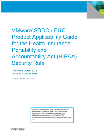
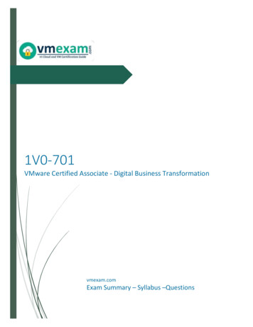
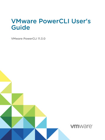
Replication FlowFigure 2-2. Outgoing Replication Path from the Source Cloud SitesourceCloud Tunnel ApplianceTunnelServiceLightweight DeltaProtocol ServicesourceCloud Replicator AppliancevSCSIfiltervSCSIfilterESXi Hostvmdk filevmdk fileData store1For outgoing replications, in the source cloud site first the vSCSI filter uses the ESXi hostVMkernel adapter network interface activated for replication for sending the replication datato the LWD Proxy in the source Cloud Replicator Appliance.Note If no interface is activated for replication, the vSCSI filter attempts using themanagement VMkernel interface.VMware strongly recommends activating vSphere Replication and vSphere Replication NFCon the VMkernel interface that transfers the replication data traffic, even when this is themanagement VMkernel interface. For more information, see Setting Up VMkernel Networkingin the vSphere documentation.2Then, the source Cloud Replicator Appliance sends the replication data to the source CloudTunnel Appliance for transferring to the destination recovery site.VMware, Inc.9
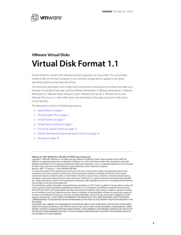
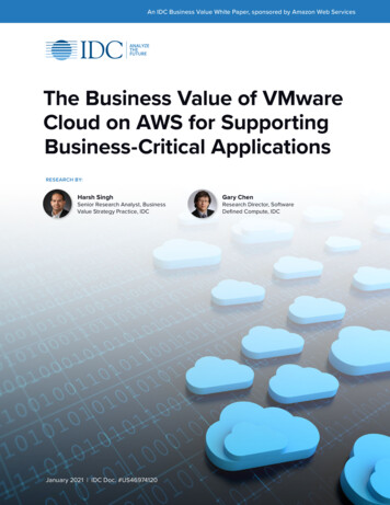
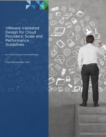
Replication FlowFigure 2-3. Incoming Replication Path to the Destination Recovery Cloud SitedestinationCloud Tunnel ApplianceTunnelServiceLightweight DeltaProtocol ServicevSphereReplication ServicedestinationCloud Replicator ApplianceNFC ServiceESXi HostBase disk Instancesand deltaimagesBase disk Instancesand deltaimagesData store1For incoming replications, in the destination cloud site the Cloud Tunnel Appliance receivesthe replication data traffic and sends it to the LWD Proxy in the Cloud Replicator Appliance inthe destination recovery site.2Then the vSphere Replication Service in the same Cloud Replicator Appliance sends thisreplication data to the Network File Copy (NFC) Service in the ESXi host in the destinationrecovery site. The NFC Service handles large amounts of data transfers like replications andbackups.Note For replication incoming traffic, one of the VMkernel interfaces of the ESXi hostmust be activated for vSphere Replication NFC. This instructs the NFC Service for receivingreplication traffic over this VMkernel interface.VMware, Inc.10
Replication Flow3Finally, the ESXi host in the destination recovery site writes the replication data to a replicafile on one of its data stores.For on-premises-to-cloud replications, the replication data path is similar. The VMware CloudDirector Availability On-Premises Appliance embeds all services, including the Tunnel Service.Replication Operations1When configuring a replication for a virtual machine, the first operation is a fullsynchronization of the disks of the virtual machine.aFirst, the Cloud Replicator Appliance instance in the destination recovery site allocates anempty vmdk file for storing the replicated blocks from the source virtual machine.bThen the vSCSI filter in the source site starts reading blocks from the source disk andcalculates checksums for each source block.cFinally, the vSphere Replication Service in the destination site calculates checksums foreach destination block in the recovery site.nWhen not using a seed virtual machine, the checksums for the same source anddestination block differ, causing the contents of this block to transfer over thenetwork from the source site to the recovery site.nWhen using a seed virtual machine, only the blocks with different checksums transferbetween the source and the destination replicator instances.2When the full synchronization completes, the vSCSI filter in the source site tracks whichblocks change, and stores the addresses of the changed blocks, also known as dirty blocks ina .psf file in the directory of the virtual machine.3Later, when the RPO window expires, the vSCSI filter in the source site reads all blocks thatchanged during the last RPO window and the VMware Cloud Director Availability appliancessend these dirty blocks to the recovery site. When overwriting a single block multiple timesduring the RPO window, only the last state of the block is replicated.This replication data transferred on each RPO window represents the delta image.4If the replication keeps multiple instances, the recovery site stores the instances togetherwith the base image. Retention rules distribute* the instances across a period of time.For example, a replication keeping four instances for a day creates an instance on every sixthhour.Usually, the RPO window is shorter than the time window between instances. As a result, inthe recovery site multiple delta images are created after creating the last instance and beforecreating the next instance. At the time for creating a new instance the following two operationstake place.1The oldest instance merges in the base image for releasing a slot for the next instance.VMware, Inc.11
Replication Flow2All delta images created after the latest instance merge in a new instance, and this becomesthe latest instance.In the recovery site, these consolidation operations of the replication data cause increased read/write storage operations.nBigger instances need longer time for consolidation.nThe same is valid for new instance creation – with more and bigger delta images the time forconsolidation in a single instance takes longer and generates more storage operations.In the recovery site, the vmdk files store the data of the base image, of the instances, and ofthe delta images. When performing a recovery or a migration, VMware Cloud Director Availabilityuses these vmdk files and creates a virtual machine, registers it in the vSphere inventory, andimports it in the VMware Cloud Director inventory.In summary, this represents the simplified form of the replication process. However, the vSphereReplication Service has other functionalities, not part of this document.* VMware Cloud Director Availability 4.3 and later allow keeping instances with different periodsof time between them. For more information, see Advanced Retention Rules in the User Guide.VMware, Inc.12
Replication Data Path3Learn more about the replication I/O operations in the source and in the destination storagesubsystems and the storage recommendations for 1-minute Recovery Point Objective (RPO).Also, learn about the vSCSI filter operations and approaches for improving the network traffic.In geographically separated data centers, see the benefits of deploying multiple VMware CloudDirector Availability instances. Learn about optimizing the Cloud Replicator Appliance instancesand the Cloud Tunnel Appliance.StorageIn the vmdk files, the vSCSI filter creates a list of blocks modified at least once during the last RPOwindow, for these dirty blocks must replicate when the RPO window expires. The ESXi host readsthese blocks before sending them over a TCP connection to the vSphere Replication Servicein the Cloud Replicator Appliance. For more information, see Chapter 2 Replication ProcessOverview.Source site storageIn the source site storage subsystem, replicating a virtual machine adds operations over whatthe virtual machine already generates. After the RPO window expires, there is a period withadditional read operations. For differing workloads, this period starts and stops at varioustimes for a variable duration.As a result, the read/write profile of the datastores changes randomly at random intervals.This inherent variability requires monitoring for correctly sizing and configuring the sourcestorage subsystem for meeting all requirements and recommendations from both the storagevendor and from VMware.Destination recovery site storageIn the recovery site, the storage subsystem also receives additional operations triggered bythe replication data traffic. The replication data is written in replica files.Consolidating the delta images in the instances generates another stream of read/writeoperations.VMware, Inc.13
Replication FlowThe merging of instances in the base disk also generates read/write disk operations. Thedeeper the hierarchy of the instance, the longer this consolidation lasts due to the increasein read/write operations. For information about the hierarchy of the instances, see UsingInstances in the User Guide.The number of write operations also depends on the way the protected application storesits data. For example, when an application frequently overwrites the same set of blocks,the write operations for instances consolidation are less than when an application randomlywrites in new blocks.NotenTo meet an RPO as short as 1-minute and ensure that the replications are free of RPOviolations, in the recovery site VMware strongly recommends using flash storage backed byNVMe or by other high-performance enterprise-grade SSD devices. Using consumer-gradeSSD might cause issues.nVMware also strongly recommends using vSphere 7.0.2 or later. By using VMware CloudDirector Availability 4.3 with vSphere 7.0.2 allows for the latest improvements in thereplication data processing. The increased level of read/write operations handling reducesthe chances for RPO violations.nVMware performs all internal product testing by using VMware vSAN datastores. However,not only vSAN can fulfill the increased demand for replications, protected by a 1-minuteRPO. Other all-flash storage solutions might also provide the necessary read/write operationshandling.nFor providing capacity to non-vSphere workloads, do not use physical disk pools that arehome of vSphere datastores. For example, NFS or SMB exports or LUNs directly attachedto servers not running ESXi. vSphere might mistake background storage operations, likeauto-tiering and disk rebalancing as unmanaged I/O traffic, resulting in a negative impact onstorage operations managed by vCenter Server.VMware recommends using vSAN as it prevents this unmanaged I/O traffic. As completelydedicated for virtual infrastructures, the vSAN datastores allow for granular observability and forcontrol over the vSAN operations. VMware actively develops the vSAN technology and improvesits performance, monitoring, recoverability, and manageability features. The vSAN policy-drivenconfiguration allows the storage administrators discovery and flexible assignment of the bestcombination of rules for any type of data stored on vSAN, including replication data. For moreinformation, see the Troubleshooting vSAN Performance, Understanding vSAN PerformanceBottlenecks, and Write Buffer Sizing in vSAN blog posts.The following example shows the impact of dynamic utilization of the recovery site datastore, forreplications configured with a target RPO of 1-minute.nThe example contains five operational virtual machines, running applications that store data inbinary format.nEach virtual machine generates from 880 to 900 MB of binary data per minute.VMware, Inc.14
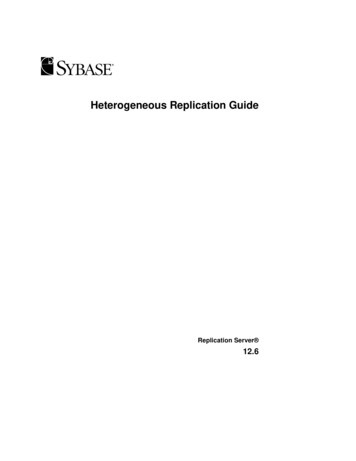
Replication FlownSome of the blocks are overwritten once or more within this minute.nIn the recovery site, a vSAN datastore receives all the replication data. This vSAN datastorealso contains other virtual machines which dynamically change the I/O pattern over thestorage subsystem, resembling a production system.In the following diagram for this example, each color represents a single replication. The bar sizeincreases with each additional minute in RPO violation.Figure 3-1. Dynamic I/O in destination site and RPO violations1First, during “Phase One”, all virtual machines residing in the recovery vSAN datastore havethe same I/O profile and only a few replications experience an RPO violation for a minute ortwo.2Later, during “Phase Two” the production workload I/O pattern increases, causing thereplications to accumulate RPO violations for extended periods of time. All replications arein RPO violations for 10 to 25 minutes.3Finally, during “Phase Three” the I/O operations in virtual machines running in the destinationsite reduces to its typical values and replications begin reducing their delays and shortly afterthey are free of RPO violations for the remaining time.During “Phase Two”, the following diagram from vRealize Operations Manager helps explain thereason for the RPO violations.Figure 3-2. vSAN write buffer dynamics in vRealize Operations ManagerVMware, Inc.15
Replication FlowIncreasing the write operations to the vSAN datastore, begins saturating its write buffer. Thisincreased write rate obstructs de-staging to the capacity drives and the vSAN datastore beginsexperiencing performance degradation. Reducing the I/O streams from the virtual machinesallows for re-obtaining the high-performance levels for write operations.Alternatively, instead of reducing the I/O stream to vSAN datastore disk groups, add morecaching drives to the vSAN cluster. Adding more caching drives is more common, and itunderlines the importance of correctly sizing the storage infrastructure and especially vSAN, ashigher cache-to-capacity ratio lowers the chances for reduced performance.vSCSI FilterThe vSCSI filter sends the replication data traffic over one of the VMkernel interfaces of the ESXihost to the vSphere Replication Service in the source Cloud Replicator Appliance instance. ThevSphere Replication Service manages the operation of the vSCSI filter.The vSphere Replication Service does not complete the synchronization of the delta image in theshortest time possible as the service keeps the following information.nThe size of the delta image.nThe maximum time to complete the previous delta images synchronization.nThe bandwidth used by the previous delta images synchronization.Based on this information, the vSphere Replication Service precisely calculates the requiredbandwidth and uses as low bandwidth as necessary for moving the delta images to the recoverysite within the RPO window. This process prevents the high utilization of the resources by thereplications. By modifying the advanced parameters of the hypervisor allows controlling thisprocess to a limited level.Note VMware recommends modifying these advanced parameters only under the guidance ofVMware support.When an RPO window expires, the vSphere Replication Service requests the ESXi host to readand send dirty blocks. Reading the dirty blocks occurs through the vSCSI filter, that is throughthe virtual SCSI interface of the virtual machine. The storage I/O limits for a virtual machine applyon the virtual SCSI adapter. When a virtual machine has a limit on the storage I/O operations, thereading of dirty blocks requested by the vSphere Replication Service respects this limit.Note Setting a low I/O storage limit might cause RPO violations and reduced performance ofthe services provided by the virtual machine. Obtain the correct numbers when such limits mustapply. This includes determining the repeatability of periods with low and high utilization andcollecting and analyzing I/O operations per second (IOPS) data for at least one full cycle andadding a portion for replication traffic.VMware, Inc.16
Replication FlowAnother key factor is the CPU processing of replicated virtual machines. The following threeitems sum the total demand for CPU cycles from a replicated virtual machine.nCPU cycles requested by the guest operating system.nCPU cycles used by the hypervisor for maintaining the virtual machine.nCPU cycles requested by the vSphere Replication Service.Based on the ESXi host resource utilization, the CPU scheduler of the ESXi host provides accessto the physical CPUs. When the ESXi host is over-utilized, the virtual machine receives its shareof CPU resources based on the number of virtual CPUs. For example, a virtual machine with eightvirtual CPUs receives twice more CPU cycles for replication processing, compared to a virtualmachine with four virtual CPUs. Instead of simply increasing the number of virtual processorsin replicated virtual machines, avoid virtual CPU over-provisioning by configuring each workloadwith the correct number of virtual CPUs.In the source site, the network traffic from the vSCSI filter to the LWDProxy is in a raw dataformat. The vSCSI filter performs no processing of the data block content.Similarly, in the recovery site, the network traffic from the vSphere Replication Service to theESXi host is in raw data format. An ESXi host in a cloud environment can run tens or hundreds ofvirtual machines that might be replicated or might be used as a destination for tens or hundredsof replications. This way, the network traffic for replication data between the ESXi hosts and theCloud Replicator Appliance instances can reach a significant volume.The architecture allows the following two approaches for improvements.1The first approach is by creating a dedicated replication network - VLAN with a dedicatedESXi host VMkernel interface. Then the Cloud Replicator Appliance instances directly connectto this network. This approach allows for the following benefits.nFor outgoing replications, the vSCSI filter in the source ESXi host sends the rawreplication data traffic directly to the LWDProxy Service in the source Cloud ReplicatorAppliance instance over a single Layer 2 broadcast domain. This prevents routing thislarge traffic volume over the routed networks and avoids the detrimental impact on theentire network infrastructure and services.nFor incoming replications, the LWDProxy Service in the destination Cloud ReplicatorAppliance instance sends raw replication data traffic to the VMkernel interface of thedestination ESXi host again over a single Layer 2 network. This prevents the routing oflarge volumes of replication data traffic and reduces the risk of impacting other types oftraffic and services.nBy using the vSphere Network I/O Control (NetIOC) allows for granular control overallocating shares to each type of network traffic and bandwidth priorities, preventingbandwidth saturation.nThis approach comes with no additional costs when the cloud provider uses vSphereEnterprise Plus and above product licenses.VMware, Inc.17
Replication FlowThis first approach requires correct planning and implementation of the following networkconfiguration changes.nCreate a VLAN network dedicated to replication data traffic.nDedicate an IP subnet for replication data traffic.nCreate a virtual port group dedicated to replication and tag it with the replication VLANID.nCreate a VMkernel adapter interface dedicated for replication, configure it with an IPaddress from the replication IP subnet and connect it to the replication virtual port group.nConfigure the network interface of each Cloud Replicator Appliance instance with an IPaddress from the replication IP subnet and connect it to the replication virtual port group.Figure 3-3. VMkernel interface with active vSphere Replication and vSphere Replication NFCFigure 3-4. Cloud Replicator Appliance and replication VMkernel interfaces connected to aport group dedicated for replication2The second approach is by using dedicated physical ESXi host uplinks for the replication datatraffic. Less frequently used, this approach comes with additional expenses like additionalphysical switch ports, additional used space in racks, and additional costs for power andcooling.When the replication VMkernel interface of the ESXi host and the Cloud Replicator Applianceinstances reside in different subnets and routing the replication data traffic between the subnets,account for the performance capabilities of the involved routing devices. For each replicatedvirtual machine, the vSCSI filter opens a single TCP session to the Cloud Replicator Applianceinstance. If the routing device performs IDS/IPS of the replication data traffic, that might causeissues.VMware, Inc.18
Replication FlowVMware strongly recommends, when possible, excluding the replication data traffic from suchinspection.The performance of the routing devices might have a negative impact on the usable networkbandwidth passing through it and might limit the number of replications or amount of replicateddata.Geographically Separated Data CentersOnly vSCSI filter and Cloud Replicator Appliance optimizations might not suffice when the cloudproviders manage a single VMware Cloud Director instance with multiple vCenter Server clusterslocated in data centers separated by a long distance.With a single VMware Cloud Director Availability instance associated with all provider VDCs, rawreplication data traffic between the vSCSI filter and the Cloud Replicator Appliance instancestravels over inter-site links once or multiple times. Also, the network traffic between the CloudReplicator Appliance instance and the Cloud Tunnel Appliance might need to travel over theinter-site link when deploying the Cloud Replicator Appliance instance and the Cloud TunnelAppliance in different data centers.The following example shows such an unoptimized replication flow between, for example, theLondon and the Berlin data centers.VMware, Inc.19
Replication FlowFigure 3-5. Unoptimized replication data flowBerlin provider VDCLondon provider VDCCloudTunnel Appliance3Cloud ReplicationManagement ApplianceCloud ReplicatorAppliance instance 1ESXi HostVMware, Inc.241Cloud ReplicatorAppliance instance 2ESXi Host20
Replication FlowIn the London data center, a single VMware Cloud Director Availability instance is deployedwithCloud Replication Management Appliance and Cloud Tunnel Appliance, with two CloudReplicator Appliance instances deployed in the London and in the Berlin data centers.Then, replicate a virtual machine hosted in the London provider VDC to the Berlin provider VDC.The Cloud Replication Management Appliance cannot know the location of each CloudReplicator Appliance instance and chooses one of the Cloud Replicator Appliance instances forcommunicating with the source ESXi host in London and another Cloud Replicator Applianceinstance for sending the replication data traffic to the destination ESXi host in Berlin.With such a topology, nothing prevents the Cloud Replication Management Appliance fromselecting a Cloud Replicator Appliance ins
Cloud-to-cloud. Replications between two cloud sites, managed by VMware Cloud Director . In each VMware Cloud Director site, VMware Cloud Director Availability consists of: n. a single Cloud Replication Management Appliance running the Manager Service and the Cloud Service providing the VMware Cloud Director Availability Portal for service