Transcription
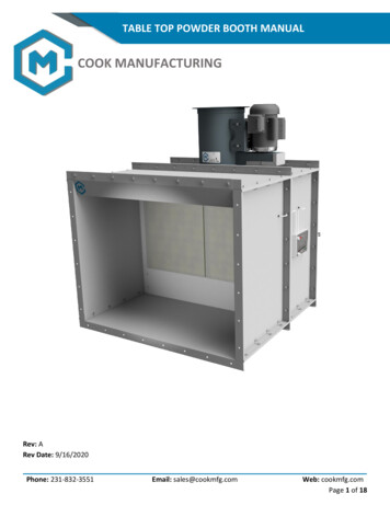
TABLE TOP POWDER BOOTH MANUALCOOK MANUFACTURINGRev: ARev Date: 9/16/2020Phone: 231-832-3551Email: sales@cookmfg.comWeb: cookmfg.comPage 1 of 18
TABLE OF CONTENTSSafety Information: . 3Safety Devices:. 3Fire Protection: . 3Static Discharge: . 3Receiving Inspection: . 3Installation: . 3Hazards: . 3Personal Protective Equipment: . 4Recommended Tools: . 4Layout: . 5Booth Assembly: . 5Grounding Rod:. 10Light Fixture: . 10Filters: . 11Manometer:. 12Tube Axial Fan: . 13Ductwork: . 13Electrical: . 14Final Inspection: . 15Start Up: . 15Operation: . 15Hazards: . 15Maintenance: . 15Hazards: . 15Schedule: . 16Warranty: . 17Phone: 231-832-3551Email: sales@cookmfg.comWeb: cookmfg.comPage 2 of 18
Safety Information:This manual should be read and understood before installing, operating, or servicing the equipment. Neverallow anyone to operate the equipment without proper training.Safety Devices:Do not attempt to bypass or eliminate any safety devices. A safety interlock that prevents the sprayequipment from operating unless the exhaust fan is running may be required. This safety interlock isnot supplied with the equipment. It is the end user’s responsibility to verify if a safety interlock isrequired with their local regulatory agency.Fire Protection:A fire suppression or protection system must be installed to comply with the National Fire ProtectionAgency’s requirements stated in NFPA 33 Section 9. Portable fire extinguishers must be in or near apaint mixing room to comply with NFPA 10. The fire suppression and protection requirements are theresponsibility of the customer and are not included with the equipment. Do not store flammableliquids in or near the paint booth. The exhaust fan must be in operation while operating, cleaning, ormaintaining the booth to remove any dangerous vapors.Static Discharge:Failure to properly ground the booth, spray equipment, and all components could create staticdischarge and result in a fire.Receiving Inspection:All shipments should be inspected for damage at the time of receipt. Any damage must be noted on thecarriers’ bill of lading. All shipping damages must be reported to our customer service team within 3 businessdays in order to fill a claim against the carrier. All items included with your order must be compared againstthe packing list. Customer must notify our customer service team of any missing parts within 7 business days.Any parts determined to be missing will be provided to the customer free of charge.Installation:Hazards: The roof is not designed to support any additional load. Do not attempt to place additionalequipment or weight on the roof.Use appropriate lifting devices to prevent injury.Phone: 231-832-3551Email: sales@cookmfg.comWeb: cookmfg.comPage 3 of 18
Personal Protective Equipment:The following list of personal protective equipment is recommended during installation.Protective EyewearHard HatSteel Toe BootsGlovesTable 1 - Recommended Personal Protective EquipmentRecommended Tools:The following list of tools is recommended for assembly.Rachet WrenchHex Socket (1/2”)Wrench (1/2”)Hex Drivers (1/4”)Drill Bits (1/8” & 3/8”)Tape MeasureDrift PinCordless DrillCaulk GunTable 2 - Recommended ToolsPhone: 231-832-3551Email: sales@cookmfg.comWeb: cookmfg.comPage 4 of 18
Layout:Proper layout and planning will reduce assembly time and ensure the equipment is installed properly.It is the end user’s responsibility to confirm proper clearances and obtain any necessary permitsrequired by their local regulatory agency. Determine the location where the booth will be installed.o The booth should be installed directly on top of a concrete floor or other nonflammablesurface.o Typically, 3’ of clearance is required around the entire booth. In some situations, your localregulatory agency may allow a booth to be installed against a wall or with less than 3’ ofclearance if the wall has the proper fire rating and the booth can still be accessed formaintenance.o A clearance of 10’ is required between the exhaust duct and the intake duct or opening ofany other equipment. The 10’ clearance is also required between the intake duct or openingand the exhaust of any other equipment.Ensure the area is level within 1/4” where the booth will be installed. Otherwise, shims will beneeded to level the booth during installation.Verify that there is proper overhead clearance in the determined location.Determine the path of the ductwork for the fan and verify that no obstructions are present.Booth Assembly:Booth panels should be orientated with flanges facing towards the outside of the booth leaving theinside of the booth smooth for cleaning. Ensure that all bolt heads are on the inside and nuts on theoutside of the booth. Leave all bolts finger tight until each section of the booth has been assembled. The assembly process will start by assembling the plenum or exhaust chamber.Phone: 231-832-3551Email: sales@cookmfg.comWeb: cookmfg.comPage 5 of 18
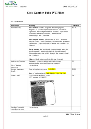
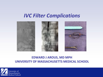
Install trim on the top and bottom of each side wall panel using 5/16-18 X 3/4 spin lock bolts andnuts. The image below shows how the panel trim is installed.Figure 1 – Panel Trim Installation Assemble the bottom and top panels to the side wall panels as shown in the image below. Notethat the flanges on the panels should be facing towards the outside of the booth leaving the entireinside of the booth smooth for cleaning.Figure 2 - Assembly of Top and Bottom PanelsPhone: 231-832-3551Email: sales@cookmfg.comWeb: cookmfg.comPage 6 of 18
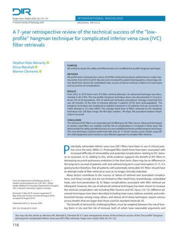
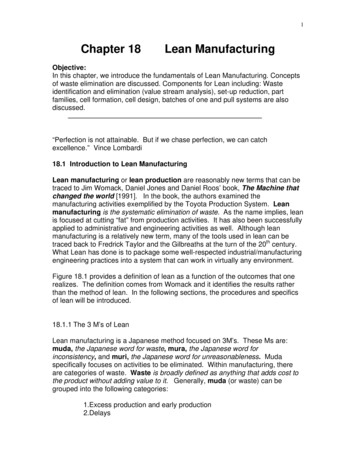
Assemble the back panels to the side walls, top, and bottom panels.Figure 3 - Assembly of Back Panels Attach the vertical plenum panel to each side wall panel of the plenum using three #8-18 X 1/2 selfdrilling screws as shown below. The vertical plenum panels should be flush with the front of theside wall panels for the plenum.Figure 4 - Installation of Vertical Plenum PanelsPhone: 231-832-3551Email: sales@cookmfg.comWeb: cookmfg.comPage 7 of 18
Place the horizontal plenum panels between the vertical plenum panels as shown in the imagebelow. Secure the panels together using two #8-18 X 1/2 self-drilling screws on each side. Thehorizontal plenum panels should also be secured to the top and bottom panels using three #8-18 X1/2 self-drilling screws.Figure 5 - Vertical Plenum Panel install Install each filter dividers using four #8-18 X 1/2 self-drilling screws as shown below. Dividers areinstalled every 20” on center to form a 20” X 20” grid.Figure 6 – Installation of Filter DividerPhone: 231-832-3551Email: sales@cookmfg.comWeb: cookmfg.comPage 8 of 18
Continue to assemble the front enclosure or working area of the booth according to the provideddrawing.Figure 7 - Assembled Enclosure Install the fire guard on the front side of the roof panel as shown below. The fire guard is attachedusing 5/16-18 X 3/4 spin lock bolts and nuts.Figure 8 - Fire Guard Install Seal all seams between the panels using a water-based sealant.Phone: 231-832-3551Email: sales@cookmfg.comWeb: cookmfg.comPage 9 of 18
Grounding Rod:The booth and spray equipment must be grounded to reduce the risk of static discharge and a possiblefire. The items required for grounding are listed below but are not included with the booth. 5/8” X 8’ Copper Grounding RodGrounding BlockGrounding CableDetermine the location for the grounding rod to be installed. Typically, the grounding rod is locatedoutside of the booth near the filter wall.Using a 5/8” diameter masonry drill bit, drill a hole through the concrete floor.Install the copper grounding rod into the hole and hammer the rod into the ground leavingapproximately 6” protruding from the floor.Attach the grounding block to the side panel of the booth.Connect the grounding block to the rod using the grounding cable.Light Fixture:The instructions below aid in the installation for the optional light fixture. All wiring should beperformed by a licensed electrician familiar with local and national codes. Take care when installing light fixtures to ensure all light fixtures are in the same orientation.Horizontally mounted fixtures should be mounted so the hinge side is up.Place light fixture into the opening of the panel and attach using twelve 1/4-14 X 3/4 self-drillingscrews as shown below.Figure 9 - Light Fixture InstallPhone: 231-832-3551Email: sales@cookmfg.comWeb: cookmfg.comPage 10 of 18
Filters:Filters trap particulates from entering the plenum, fan, and ductwork. Excessive buildup of particulateswill reduce the life span of the fan and require more frequent cleaning of the plenum and ductwork.Never operate the booth without all filters installed. Install a bag filter into each opening of the filter grid.Install the filter holding grid into each opening. Verify the angled prongs are facing towards you.Adjust the rubber tips on the filter holding grid as needed to ensure a snug fit.Install polyester prefilter into each opening by pressing the filter over the prongs on the wire filterholding grid. The dense side of the filter should be towards the plenum.Figure 10 – Plenum Filter Install The image below shows an optional diffuser assembly that can be purchased to recirculate theexhaust indoors.Figure 11 - Diffuser Filter InstallPhone: 231-832-3551Email: sales@cookmfg.comWeb: cookmfg.comPage 11 of 18
Install the diffuser panel filters into each side of the diffuser assembly as shown below. The denseside of the filter should be facing outwards.Slide the filter holding rod behind each filter and secure using a hairpin clip.o Note: The holding rod is only used for fans 18” and larger.Manometer:A manometer measures pressure levels and is used to indicate when the filters need to be changed.The manometer should be mounted on the side of the booth no more than 24” from the filter wall.Figure 12 - Manometer Place the manometer on the side of the booth at the desired height and within 24” from the filterwall. Mark the mounting hole locations and remove the manometer.Drill the marked hole locations using an 1/8” diameter drill bit.Loosely mount the manometer using the two self-tapping screws that are provided.Adjust the manometer until level and tighten screws.Turn the “Zero Set” knob counterclockwise until you reach the stop position.Turn the “Zero Set” knob clockwise three full revolutions. This ensures the manometer is at themiddle of its range.Remove the fill plug and slowly add the fluid until the manometer reads near zero.Replace the fill plug and adjust the “Zero Set” knob until the manometer reads exactly zero. A pipecleaner can be used to remove fluid if needed.Drill a 3/8” diameter hole on each side of the filter wall.Insert the barbed fittings into the two holes. Secure fittings using a washer and nut from the insideof the booth.Connect the high-pressure port on the manometer to the barbed fitting in the working area of thebooth using the provided tubing.Connect the low-pressure port on the manometer to the barbed fitting in the plenum area usingthe provided tubing.Phone: 231-832-3551Email: sales@cookmfg.comWeb: cookmfg.comPage 12 of 18
Figure 13 - Manometer Install Complete the installation of the booth before continuing.Set the low operating limit by turning on the exhaust fan with all filters installed. Note that thereading on the manometer should increase and settle. Mark the location on the manometer withthe green arrow sticker.Determine the high limit of the manometer by taking the low limit and .50”. Mark the high limitlocation on the manometer using the red arrow sticker. Filters should be changed promptly oncethe manometer reaches the high limit value. Operating the equipment above the high limit valuewill result in poor filtration and additional strain on the exhaust fan motor.Periodically, check the manometer to ensure it reads zero while the exhaust fan is off. If needed,the “Zero Set” knob can be used to adjustTube Axial Fan:The tube axial fan pulls air and fumes from the working area of the booth and discharges the airthrough the ductwork. Lift the tube axial fan from the mounting rings. Do not lift from the motor, shaft, or blade.Place the fan on top of the booth or plenum.Make sure the fan is orientated properly.o A sticker on the side of the fan will indicate the direction of airflow.o Make sure the motor can be easily accessed for maintenance.Secure the exhaust fan to the booth using 5/16-18 X 3/4 spin lock bolts and nuts.Caulk the connection between the fan and booth using a water-based sealant.Ductwork:The exhaust system of the booth must terminate outside. Typical exhaust configurations includeexhausting through the roof or exterior wall. Typically, the exhaust duct must protrude 6’ above theroof before the rain cap or auto damper is installed to meet code requirements. Ductwork must alsoterminate at least 10’ away from any openings. Check your local zoning and ordinances to ensurecompliance.Phone: 231-832-3551Email: sales@cookmfg.comWeb: cookmfg.comPage 13 of 18
Layout:The following requirements must be met when determining the ductwork layout. Failure tomeet any of these requirements will void the warranty of the fan. Contact Cook Manufacturingif you need assistance or have any questions regarding proper ductwork layout. All ductwork must be the same diameter as the fan. Reducing the diameter of the ductcreates additional static pressure, lowers airflow, and reduces the operational life of thefan.A straight section of duct at least one and a half times the diameter of the fan is requiredbefore and after each elbow.A maximum of two elbows can be used.Total length of ductwork must not exceed 25’.Assembly: Determine the location where the ductwork will exit the building. A laser or plumb bob canbe used to aid in determining the location.Cut the appropriate size hole in the roof or exterior wall.Attach ductwork to the tube axial fan using 5/16-18 X 3/4 spin lock bolts and nuts.Connect ductwork sections together using 5/16-18 X 3/4 spin lock bolts and nuts.Support ductwork to the building as needed. The ductwork should be fully supported so thefan can be removed if needed for maintenance. The booth is not designed to support theweight of the ductwork.Seal all joints of the ductwork using a water-based sealant.Reference ductwork manual for more detailed instructions.Electrical:All electrical activities must be performed by a licensed local electrician who is familiar with both localand national codes.Disconnect Switch:Power should be supplied to the control box, VFD, or fan motor from an independentdisconnect switch. The disconnect should be in close proximity to the fan so power can be shutoff in case of an emergency. Disconnect switches should have the ability to be locked outanytime an inspection or maintenance is performed according to OSHA’s lock out tag outprocedure. All disconnects should be sized and rated according to the latest NEC or NationalElectrical Code along with any local codes. Time delayed fuses are recommended to be usedwith all disconnects.Phone: 231-832-3551Email: sales@cookmfg.comWeb: cookmfg.comPage 14 of 18
Wiring: Confirm the voltage available at your facility.Confirm that the voltage of the electrical device to be wired matches the voltage beingsupplied.A wiring diagram can be found on the junction box cover or name plate of the electricmotor. Locate the wiring diagram for your voltage.Select motors may have two additional red wires for a thermal overload. These wires arenot used and should be capped individually using wire nuts.Verify that the rotation of the motor matches the direction of rotation noted on the fanassembly.Final Inspection: Check that all fasteners on the fan and mating ductwork have been properly tightened.Check that the fan, ductwork, and surrounding area are free from any debris or tools that could besucked into the fan. Debris sucked into the fan could cause injury or death.Start Up: Momentarily apply power to the fan to check for proper rotation.Verify that the fan blade is spinning in the correct direction according to the rotation arrow on label.Refer to the wiring diagram if the rotation needs to be changed.If no issues are found, the fan should be in operation for no more than 16 hours before the firstmaintenance inspection is performed. The standard maintenance schedule can be used for all futuremaintenance planning.Operation:Hazards: Do not allow anyone to operate or perform maintenance without proper training.Do not operate any portable equipment inside or near the paint booth.Read and understand the safety data sheets for all products being used in the paint booth.Maintenance:Hazards: Disconnect and lockout all power sources before performing any maintenance activities.All maintenance should be performed by trained and qualified personnel.Read and understand all safety data sheets for the products used in the paint booth.Phone: 231-832-3551Email: sales@cookmfg.comWeb: cookmfg.comPage 15 of 18
Schedule:ItemFiltersEnclosureManometerFan BearingsBelt TensionFan uallyAnnuallyXXXXXXTable 3 - Maintenance ScheduleFilters:Inspect filters for damage, separation, and buildup of paint and debris. Filters should bereplaced when damage or separation is present. Properly handle and dispose of all used filtersas they represent a fire hazard. All discarded filters must be removed to a safe, well-detachedlocation or placed in a container filled with water.Enclosure:Remove any debris and overspray from the floor, walls, and ceiling using a non-sparkingscrapper and appropriate cleaner. We recommend applying a peelable booth coating whichreduces the amount of time to properly clean the booth.Manometer:Check that the manometer indicates zero while the exhaust fan is off. If needed, adjust the“Zero Set” knob until the manometer reads zero.Bearings:Grease bearings using a high quality NLGI Grade 2 grease. Ensure the grease is added slowlywhile spinning the fan by hand until clean grease can be seen exiting the bearing. Typically, only1 pump of grease is needed per month.Belts:Belt Tension must be inspected and adjusted after the first 16 hours of operation. Inspect beltsfor proper tension and wear semiannually. Replace belts immediately if signs of excessive orabnormal wear are visible.Phone: 231-832-3551Email: sales@cookmfg.comWeb: cookmfg.comPage 16 of 18
Fan Housing:Inspect the fan housing and blade for excessive buildup of particulates. Excessive buildup cancause premature failure of the blade and bearings. Remove any buildup using a non-sparkingscrapper and appropriate cleaner. Verify the entire blade must be thoroughly cleaned to ensurethe blade is balanced.Motor:Remove any dust or grease from the exterior surface of the motor. Excessive buildup of dustcan lead to an increased operating temperature and reduce the overall life of the motor.Duct Work:Inspect ductwork for excessive buildup of particulates. Excessive buildup can restrict airflowand presents a fire hazard. Remove any buildup using a non-sparking scrapper and appropriatecleaner.Warranty:Cook Manufacturing Company LLC (the Seller) warrants to the original end-user buyer (the Buyer) that theequipment manufactured by, and purchased from, the Seller (the Equipment), if properly installed, operated,and maintained in accordance with the Seller's manuals, and used under normal conditions, shall be free fromdefects in materials and workmanship for a period of one (1) year from the date the Equipment is shippedfrom the Sellers facility. The obligation of the Seller, and the Buyer's sole and exclusive remedy hereunder,shall be limited to one of the following, at the Seller's option: The repair or replacement of defective parts or components (collectively, the Parts) of the Equipment;provided, however, the Buyer shall be responsible for the payment of all transportation and labor costsassociated with any such repair or replacement. In the event the Seller is unable to repair or replace the defective Parts, the Buyer shall be entitled to arefund of the cost of the Parts.The Seller shall have no obligation under this Limited Warranty for ordinary wear and tear of the Equipment; ifinstallation of the Equipment does not comply with the local, state and federal requirements or laws; or if theEquipment is modified by any other person or organization. The Seller makes no warranty of any kindwhatsoever with respect to Parts which are manufactured or supplied by other persons or organizations (anOEM); provided, however, the Seller shall reasonably assist the Buyer in connection with warranties, if any,provided by an OEM.Phone: 231-832-3551Email: sales@cookmfg.comWeb: cookmfg.comPage 17 of 18
Warranty Performance Procedure:In the event the Buyer believes the Seller may be responsible for the performance of any warranty obligation,the Buyer must immediately send written notice of a claimed defect and must immediately refrain from anyfurther use of the affected Equipment. No attempted repair of the claimed defect may be made without theprior written consent of the Seller. Before any Parts can be returned to the Seller, the Buyer must contact theSeller and request a Return Authorization. Upon the Buyer's receipt of the Return Authorization form, theParts may be shipped, freight prepaid, to the facility designated on the Return Authorization. All Partsreturned for repair, replacement, or refund (which refund may be made in the form of a credit to the Buyer'saccount), must be accompanied by the Return Authorization. All returned Partsare subject to a twenty percent (20%) handling charge. Parts manufactured or supplied by an OEM are subjectto warranties, if any, provided by such OEMs; and repair or replacement of such Parts are subject to theapproval of the OEM. The Buyer shall be responsible for the payment of any handling or restocking chargesassociated with OEM Parts.Disclaimers of Warranties:The warranties contained herein are expressly in lieu of any other expressed or implied warranties, or anyother obligation on the part of the Seller, including without limitation, any implied warranty of merchantabilityor fitness for a particular purpose. Any models, drawings, specifications, affirmations of fact, promises, orother communications by the Seller with reference to the equipment or performance of the equipment aresolely for the convenience of the Buyer and shall not in any way modify the express warranties and disclaimersset forth herein. The Buyer acknowledges it is purchasing the equipment solely based on the commitments forthe Seller as expressly set forth herein. No agents or other parties are authorized to make any warranties onbehalf of the company or to assume for the company any other liability or obligation in connection with theequipment.Consequential Damages:The Seller shall not be liable for any incidental or consequential damages arising from the use of theequipment by the Buyer, the breach of any warranties, the failure to deliver, delay in delivery, delay onnonconforming condition, or for any breach of contract or duty between the Seller and the Buyer.Limitation of Actions:Any action resulting from the breach of any warranty contained herein by the Seller must be commencedwithin one (1) year after the cause of action accrues. In no event shall the Seller's total liability for any or allbreaches of any warranty exceed the actual purchase price paid by the Buyer for the Equipment.Phone: 231-832-3551Email: sales@cookmfg.comWeb: cookmfg.comPage 18 of 18
The following list of personal protective equipment is recommended during installation. Protective Eyewear Hard Hat Steel Toe Boots Gloves . Grounding Rod: The booth and spray equipment must be grounded to reduce the risk of static discharge and a possible fire. The items required for grounding