Transcription
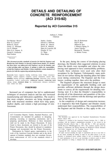
DETAILS AND DETAILING OFCONCRETE REINFORCEMENT(ACI 315-92)Reported by ACI Committee 315Anthony L. FelderChairmanStanley GordonEdward S. HoffmanRobert W. JohnsonDavid W. JohnstonHarry B. Lancelot, IIIDouglas D. LeeJ.I. MannPeter MezaTed Maclean Brown*Peter D. Courtois*Robert E. DoyleGustav G. ErlemannLeo P. FlibotteJules O.A. Gagnon, Jr.Gerald E. GoettschePaul Gordon*Roy H. ReitermanPaul F. RiceMilton R. SeesJ. Maurice Spang, Jr.Anton TedeskoBertrand K. ThornleyA. Robert VernecDeceasedThis document provides standards of practice for both the Engineer andReinforcing Steel Detaiier in showing reinforcement details. It is dividedinto three parts: one addressed to the Engineer, one for the Detailer, anda third providing tables and figures. It attempts to define the responsibilitiesof both the Engineer and Detailer. It then establishes certain standards ofpractice for both the engineering and placing drawings.Keywords: beams (supports); bending (reinforcing steels); bridges (structures);buildings; columns (supports); computers; concrete construction; concrete slabs;detailing; drafting (drawing); engineering drawings; fabrication; floor systems;foundations; hooked reinforcement; reinforced concrete; reinforcing steels;splicing; stirrups; structural design; ties (reinforcement); tolerances (mechanics);walls; welded wire fabric.FOREWORDIncreased use of computers has led to sophisticatedtechniques of structural analysis and has also increasedmanufacturing and fabrication capabilities. The result isthat more complex structures are being designed andbuilt with structural members which have long spans,shallow depths, and contain a high percentage of reinforcement.ACI Committee Reports, Guides, Standard Practices, andCommentaries are intended for guidance in designing,planning, executing, or inspecting construction, and inpreparing specifications. Reference to these documentsshall not be made in the Project Documents. If itemsfound in these documents are desired to be part of theProject Documents, they should be phrased in mandatorylanguage and incorporated into the Project Documents.Participation by Federal agency representatives in thework of the American Concrete Institute and in the development of Institute standards does not constitute Government endorsement of ACI or the standards which itdevelops.In the past, during the course of developing placingdrawings, the Detailer often suggested solutions in areaswhere the details were incomplete and where the reinforcing steel appeared to have constructibility problems.Usually these solutions were used only after theiracceptance by the Engineer. Unfortunately, many problems do not surface during the detailing phase but ratheroccur during construction. The Engineer and the Contractor, working together, then solve the problem.The Engineer prepares the structural design to meetthe requirements of the applicable building code andprovides sufficient definition through the design documents to convey all the requirements for detailing reinforcing steel. It is then the Detailer’s responsibility todevelop all of the dimensions and quantities of the reinforcing steel to conform with the drawings and specifications of the Engineer.As the complexity of design and construction increase,it is imperative that both Engineer and Detailer clearlyunderstand their responsibilities. The responsibilities ofthe Engineer and the Detailer as they apply to the con-The document was approved by the Expedited Standardization Procedureeffective March 1992.Adopted as a standard of the American Concrete Institute, Oct. 1, 1980, inaccordance with the Institute’s standardization procedure. It was revised by theExpedited Procedure effective Sept. 1, 1986, and Mar. 1, 1992, and supersedes315-80 (Revised 1986)(Reapproved 1991). This standard, together with the“Manual of Eugineering and Placing Drawings for Reinforced Concrete Structures(ACI 315R)," comprises the ACI Detailing Manual, SP-66.Copyright 0 1992, American Concrete Institute.All rights reserved including the rights of reproduction and use in any form orby any means, including the making of copies by any photo process, or by anyelectronic or mechanical device, printed, written or oral, or recording for soundor visual reproduction or for use in any knowledge or retrieval system or device,unless permission in writing is obtained from the copyright proprietors.DETAILS AND DETAILING1
crete industry are stated more clearly by providingseparate sections for each.Chapter 8-References, pg. 315-20PART C-FIGURES AND TABLESCONTENTSFig. l-Typical details for one-way solid slabs, pg. 315-22Fig. 2-Typical details for beams, pg. 315-23PART A-RESPONSIBILITIES OF THE ENGINEERFig. 3-Typical details for one-way joist construction, pg.Chapter l-Engineering drawings, pg. 315-3315-241. l-GeneralFig. 4-Standard fabricating tolerances for bar sizes #31.2-Drawing standardsthrough #ll, pg. 315-251.3-Engineering drawings-Buildings and otherFig. 5-Standard fabricating tolerances for bar sizes #14structuresand #18, pg. 315-271.4-Engineering drawings-Highway and TransFig. 6-Typical bar bends, pg. 315-28portation structuresFig. 7-Column splice details, pg. 315-29Fig. 8---One-piece column ties applicable for lap-splicedChapter 2-Standards of practice, pg. 315-4preassembled cages, pg. 315-30Fig. 9-Universal column ties for standard columns ap2.1-General2.2-Tolerancesplicable for either preassembled cages or field2.3-Combination drawingserection, pg. 315-3 12.4-Hooks and bendsFig. l0-Universal column ties applicable for either pre2.5-Beams and girdersassembled cages or field erection: special2.6-Columnsshaped columns and columns with bars in two2.7-Development and splices of reinforcementfaces only, pg. 315-322.8-Connection detailsFig. ll-Typical wall details shown in horizontal cross2.9-Reinforcement supportssection, pg. 315-332.10-Special details for seismic design of frames,Fig. 12-ACI 318 requirements for anchorage of openjoints, walls, diaphragms and two-way slabsstirrups, pg. 315-332.1l-Corrosion resistant coatings for reinforcementFig. 13-Recommended two-piece closed single and multiple U-stirrups, pg. 315-34PART B-RESPONSIBILITIES OF THE DETAILER Fig. 14-Not Recommended-Closed stirrup styles conChapter 3-Placing drawings, pg. 315-12sidered ineffective for members subjected to3.1-Definitionhigh torsion stress, pg. 315-343 . 2- S c o peFig. 15-Typical seismic-resistant details-Flexural mem3.3-Procedurebers, pg. 315-353.4-Drawing standardsFig. 16-Typical seismic-resistant details--Columns, pg.3.5-Building drawings315-363.6-Highway drawingsFig. 17-Example of transverse reinforcement in col3.7-Detailing to fabricating standardsumns, pg. 315-37Fig. l&-Typical ductile frame-spandrel joint details, pg.Chapter 4-Fabricating practice standards, pg. 315-17315-384.1-FabricationFig. 19-Boundary members, pg. 315-394.2-ExtrasFig. 20-Recommended layout for placing drawings, pg.4.3-Tolerances315-39Fig. 21-Typical bar lists for buildings, pg. 315-40Chapter 5-Supports for reinforcement, pg. 315-18Fig. 22-Typical bar list for highway structures, pg.5. l-General315-415.2-Types of bar supportsFig. 23-Location of bars designated only by size/spacing,5.3-Side form spacers and beam bolsterspg. 315-425.4-Placing reinforcement supportsTable l-Standard hooks, pg. 315-44Chapter 6-Computer-assisted detailing, pg. 315-19Table 2a-Maximum number of bars as a single layer in6.1-Use of computers in detailingbeam stems conforming to ACI 318, pg. 3156.2-Placing drawings456.3-Ordering proceduresTable 2b-Maximum number of bars as a single layer inbeam stems or columns, pg. 315-46Chapter 7-Recommended practices for location of bars Table 3-Maximum number of bars as a single layer inbeam stems conforming to AASHTO “Standarddesignated only by size/spacing, pg. 315-202DETAILS AND DETAILING
Specifications for Highway Bridges,” pg. 31547Table 4-Maximum number of bars in cast-in-placeround columns based on ACI 318 requirements, pg. 315-48Table 5-Maximum number of bars that can be accommodated in a column face, using mechanicalend-bearing connections based on ACI 318, pg.315-49Table 6-Maximum spacing of column ties per ACI 318,Section 7.10.5.2 ,pg. 315-49Table 7-Minimum requirements for column spiralspacers, pg. 315-49Table 8-Bundled bars as column verticals-Design anddetail data, pg. 315-50Table 9-Compression embedment and lap splices forgrade 60 bars, bar diameters, pg. 315-50Table l0-Tension development length (in.) for grade 60uncoated bars in normal weight concrete, pg.315-51Table ll-Tension lap splice length (in.) for grade 60uncoated bars in normal weight concrete, pg.315-52Table 12-Tension development length (in.) for grade 60epoxy-coated bars in normal weight concrete,pg. 315-53Table 13-Tension lap splice length (in.) for grade 60epoxy-coated bars in normal weight concrete,pg. 315-55Table 14-Minimum tension embedment lengths Zdb (in.)for standard end hooks on grade 60 bars innormal weight concrete, pg. 315-56Table 15-Minimum tension embedment lengths Zdb (in.)for standard end hooks on grade 60 bars inlightweight aggregate concrete, pg. 315-57PART A-RESPONSIBILITIES OFTHE ENGINEERCHAPTER l-ENGINEERING DRAWINGSl.l-GeneralEngineering drawings are those prepared by theEngineer for the Owner or purchaser of engineering services. The engineering drawings and the project specifications form a part of Contract Documents. Engineeringdrawings should contain an adequate set of notes and allother essential information in a form that can be quicklyand correctly interpreted. These drawings should conveydefinite instructions and show reinforcing bars andwelded wire fabric. Engineering and placing drawingsmay be combined.*The responsibility of the Engineer is to furnish a clearstatement of design requirements; the responsibility ofthe Detailer is to carry out these requirements. The Engineer’s specifications or drawings should not merelyrefer the Detailer to an applicable building code forinformation to use in preparing placing drawings. Instead,this information should be interpreted by the Engineerand shown in the form of specific design details or notesfor the Detailer to follow. Where omissions, ambiguities,or incompatibilities are discovered, additional information, clarifications, or corrections should be requestedby the Detailer and provided by the Engineer. The Engineer should require in the specifications that placingdrawings be submitted for approval.Section 1.2.1 of the ACI 318 Building Code lists theinformation that shall be shown on the structuraldrawings, which includes the following:l Anchorage length of reinforcement and locationand length of lap splicesl Type and location of welded splices and mechanicalconnections of reinforcement1.2-Drawing standards1.2.1 Materials-The minimum standard media forproduction of engineering drawings should be pencil ontracing paper. Other media providing improved reproducibility or durability such as ink, tracing cloth, orpolyester film may be utilized.1.2.2 Sizes-Drawings should be made in standardsizes. All sheets in any one set of drawings should be thesame size. There are two well-recognized sets of standardsizes.Commercial standards:18 x 24 in.24 x 36 in.27 x 36 in.30 x 42 in.Federal agencies:17 x 22 in.22 x 34 in. 2 in. binding (AASHTO)28 x 40 in. 2 in. binding30 x 42 in.All dimensions are to cutting line outside of margin.Border lines are inside these dimensions.1.2.3 Direction-An arrow indicating the direction ofnorth should be placed on every drawing which containsa plan view.1.2.4 Scales-The scales used should be indicated onall engineering drawings, preferably under the title ofeach view. Drawings that may be enlarged or reduced inreproduction should show a graphic scale as well as adescriptive one to aid the user.1.2.5 Lettering- All lettering shall be clear and legible.If reduced-scale photographic prints are to be made forfield use, lettering must be correspondingly larger, andmeet microfilming standards in accordance with theNational Microfilm Association publication “ModernDrafting Techniques for Quality Microreproductions.”* Requirements for placing drawings are in Part B, addressed to the Detailer.RESPONSIBILITIES OF ENGINEER 3
1.3-Engineering drawings-Buildings and other structures1.3.1 General-Engineering drawings and/or specifica-tions for elements like beams, girders, columns, walls,and foundations shall show type and grade of steel, anyspecial coatings, service live load, partition, ceiling andhanging loads, or any special dead loads other than theself-weight and concrete strength. Engineering drawingsand/or specifications shall also show concrete dimensions,anchorage length of reinforcement and location andlength of lap splices, type and location of welded splicesand mechanical connections of reinforcement, concretecover for the reinforcement, required joints, and anyother information needed for the preparation of reinforcement placing drawings. Sleeve locations and anyspecial reinforcement around sleeves or openings shouldbe indicated by the Engineer. See Fig. 1, 2, 3, 7, 15, 16,and 18. In addition to these requirements, engineeringdrawings of beams, girders, and columns should alsoshow the information presented below.1.3.2 Beams and girders-Schedules for beams andgirders must contain: the beam mark; size of member;number and size of straight and bent bars; special noteson bending; number, size, grade, and spacing of stirrupsor stirrup-ties; location of top bars; and any specialinformation, such as the requirement of two layers ofsteel. Show sections for beam-column joints, wherenecessary.In continuous beams the number and spacing of topbars to be placed in T-beam flanges (slabs) for crackcontrol must be shown, if so required by the design.1.3.3 Columns-Column designs must show size ofcolumns, number, locations, grade and size of reinforcement, and all necessary details where column sectionor reinforcement changes. Splicing must always be clearlydefined, showing arrangement of splices, whether butt orlapped, any staggers, and type of connection required forbutt splices. Orientation of reinforcement in two-waysymmetrical columns must be shown when reinforcementis not two-way symmetrical.welded wire fabric must show the mark, style, width,length and number of pieces.Reinforcement for larger structures is sometimesdetailed, fabricated, and delivered by units, for example,footings, abutments, piers, and girders. The reinforcement list may be similarly subdivided. If the structure issufficiently large, a separate drawing and reinforcementlist is usually made for each unit.Reinforcement for foundations, piers, abutments,wingwalls, and slabs are usually shown on the plan,section, or elevation. Cross sections must be provided forclarification where necessary. The reinforcement list mustbe a complete summary of materials required.For reference data on reinforcing bars and weldedwire fabric from industry sources, refer to the SupportingReference Data section of this manual. This sectionincludes specific information on applicable ASTM specifications, coated reinforcing bars, common stock stylesand design data for welded wire fabric, and reinforcingbar supports.CHAPTER 2-STANDARDS OF PRACTICE2.1-GeneralThis chapter provides the Engineer with minimumstandards for application during the development of thedesign. Information presented here is a collection ofnotes derived from ACI 318; ACI 343R; AREA “Manualfor Railway Engineering,” Chapter 8, Concrete Structuresand Foundations; and AASHTO “Standard Specificationsfor Highway Bridges,” (restated for emphasis and convenience), industry practice, practical considerations, andresearch results current at the time of this report. Reinforcement for structures designed under the provisions ofACI 349,* ACI 359, and other similar documents cangenerally incorporate the direction given in this standardunless otherwise prohibited by the provisions of therespective related documents.2.2-Tolerances1.4-Engineering drawings-Highway and transportationstructures*1.4.1 Dimensions-Since the engineering drawings forhighway structures usually are a combination of engineering and placing drawings from which the structurewill be built, all dimensions should be clearly shown.Drawings must show the dimensions of concrete protection for all reinforcement.? Where separate placingdrawings are prepared, structural dimensions may beomitted following the same practice as for buildings (seeSection 3.5).1.4.2 Reinforcement -Combination engineering-placingdrawings must show the size, spacing, and location of thebars and welded wire fabric in the structure. The list ofbars must show the number of pieces, size, length, markof bars, and bending details of all bent bars. The list of4RESPONSIBILITIES OF ENGINEERPractical limitations of equipment and productionefficiency have led to establishment of certain fabricationtolerances which can be met with standard shop equipment. These standard tolerances are shown in Fig. 4 and5 for both straight and bent bars. Where more restrictivetolerances are required than those shown in the referenced figures, they should be indicated in the ContractDocuments. The effects of tolerances on cover, strength,constructability, and serviceability of the structure shouldbe considered by the Engineer.* The term “highway and transportation structures” used herein includes bridges,drainage, and related structures.t Subject to requirements of ACI 318, Section 7.7.1 or AASHTO bridgespecification. Code Requirements for Nuclear Safety Related Concrete Structures.0 Code for Concrete Reactor Vessels and Containments.
2.3-Combination drawingsCombination engineering-placing drawings shouldshow all bar dimensions as out-to-out with bar lengths asthe sum of all detailed dimensions, including Hooks Aand G (Table 1).2.4-Hooks and bendsHooks and bends are specified to standardize the fabrication procedure and to limit the concrete stresses inthe area of the hooks. See Table 1 and Fig. 6.2.5-Beams and girders2.51 Beam widths-To permit satisfactory placing ofconcrete and to protect bars from corrosion, the Engineer must provide for adequate clear distance betweenparallel bars and between bars and forms.The Engineer must specify the required concreteprotection for the reinforcement. The Engineer must alsospecify the distance between bars for bond developmentand concrete placing. For buildings, the clear space is atleast one bar diameter, 11/2 times the maximum size ofcoarse aggregate to be used, but not less than 1 in. Forcast-in-place bridges, required clear space is not less than1.5 bar diameters, 1.5 times maximum size aggregate, nor1.5 in.Table 2 gives a wide range of beam widths and themaximum number of bars permitted in a single layer for3/ in. and 1 in. maximum aggregate size, respectively, asprovided by ACI 318. Table 3 similarly gives the sameinformation for beams designed under the provisions ofthe AASHTO bridge specifications. These tables areprovided for the use of the Engineer; the Detailer is notin a position to determine whether bars should bepermitted to be placed in more than a single layer.2.52 Stirrup anchorage-The Engineer must show orspecify by notes the sizes, spacings, location, and types ofall stirrups. These types include open stirrups and closedstirrups (or stirrup-ties) (Fig. 12 and 13). Stirrups canalso be fabricated from welded wire fabric.There are various permissible methods of anchorage,but the most common is to use one of the standardstirrup-tie types as shown in Fig. 6. Types S1 through S6,Tl, T2, and T6 through T9 use standard tie and stirruphooks as shown in Table 1. Where stirrup support barsare required, they must be specified by the Engineer. Indesigning the anchorage, allowance must be made toinsure that the ends of the stirrup hook are fully encasedin concrete, as when hooks turn outward into shallowslabs.Where the design requires closed stirrup-ties forvertical shear, the closure may consist of overlappedstandard 90-deg end hooks of one- or two-piece stirrups,or properly spliced pairs of U-stirrups. Where designrequires closed ties for torsion, the closure may consist ofoverlapped standard 135-deg hooks of one- or two-pieceties enclosing a longitudinal bar. At least one longitudinalbar must be located inside each corner of the stirrups orties, the size of this bar to be equal to at least thediameter of the stirrup (#4 minimum). Ties provided toresist radial forces resulting from bar or tendon curvaturemust be adequately anchored.2.53 Spacings of bundled bars-When bars are placedin contact with each other in groups of two, three, orfour-known as “bundled bars”-the minimum clearspace provided between bundles for buildings under ACI318 must be equal to the diameter of a single round barhaving an area equivalent to the area of the bundle. Forbridge design, AREA and AASHTO bridge specificationsrequire a minimum spacing equal to 1.5 times diameterof a single equivalent bar.2.6-Columns2.6.1 Column verticals--In selecting reinforcement forcolumns, consideration should be given to the minimumspacing of bars or bundles required by Section 7.6.3 ofACI 318. Table 4 shows the maximum number of barsfor round columns, and Table 5 indicates the maximumnumber of bars that can be placed in one face of a rectangular column. Splice arrangements must be shown.For butt-spliced systems, an allowance must be includedfor increase in diameter at mechanical connections, andfor access to weld. Special end preparation required forbars must be shown or specified. Where the steel arearequired above is different from that in the columnbelow, the engineering drawings must clearly show theextension required (if any) of all reinforcing bars aboveand below the floor level (see also Section 2.7).2.6.2 Offset between column faces-Where there is achange in size of a column, the engineering drawingsmust show how the vertical bars are to be offset, orseparate dowels must be shown (see Section 3.7.7.2). Theslope of the inclined portion should not exceed 1 in 6.See Fig. 7 for recommended splicing details.Where column verticals are offset bent, additional tiesare required and should be placed not more than 6 in.from the point of the bend. For practical purposes, threeclosely spaced ties are usually used, one of which may bepart of the regularly spaced ties plus two extra ties. General arrangements of vertical bars and all tie requirements should be established by the engineering drawings.In addition to showing size and regular spacing ofcolumn ties, the Engineer must also show any additionalties required for special conditions such as splices,offset-bends, etc.2.6.3 Changing bar arrangement between floors-Whenthe bar arrangement is changed at floors, bars mayextend through, terminate, or require separate dowels.Reinforcement at least equal in area to that in thecolumn above should be extended to lap bars above bythe required lap length or butt splices should be provided. Vertical bars from the column below terminatedfor any reason are cut off within 3 in. of the top of thefinished floor unless otherwise indicated on the engineering drawing. The Engineer must determine what, ifany, additional extension of discontinued column verticalsRESPONSIBILITIES OF ENGINEER 5
is required for adequate embedment, and show it on theengineering drawings.2.6.4 Spirals -Pitch or spacing of spirals should begiven to the nearest quarter inch. According to ACI 318,the clear spacing between spiral turns should not exceed3 in. or be less than 1 in. or 1-s times the maximum sizeof coarse aggregate used. Spirals should be provided with1-s extra turns at both top and bottom. If necessary tosplice a spiral, it should be done by welding or by a lapsplice of 48d b.Minimum diameters to which standard spirals can beformed and minimum diameters which are consideredcollapsible are shown below for various sizes of spiralbars.Minimum outsidediameter whichcan be formed,(in.)Minimum outsidediameter ofcollapsible spiral,(in.)Ya9l/278% (special)121530141824-Spiral bardiameter,(in.)Spirals are used primarily for columns, piers, anddrilled caissons, but are also used in piles. Continuouslywound reinforcement in the form of a circular helix notmeeting the ACI 318 definition of a spiral may be usedin these structures as tie reinforcement. Such reinforcement, sometimes referred to as continuous ties, areusually specified with a large pitch.2.6.5 Column ties---The vertical bars in tied columnsmust be tied together laterally. Standard arrangements ofties for various numbers of vertical bars are shown in Fig.8, 9, and 10. The Engineer may also specify welded wirefabric with an equivalent area of steel for column ties.The arrangements of one-piece ties shown in Fig. 8 provide maximum rigidity for column cages preassembled onthe site before erection. Preassembly is preferred only forthe common designs employing one-story length verticalbars all lap spliced at or near one point above the floorline. See Section 2.7.3 for lap splice restrictions.With staggered butt splices on large vertical bars intwo-story lengths, practical erection limitations usuallyrequire that column ties be assembled on free-standingvertical bars. Standard arrangements for two-piece column ties shown in Fig. 9 and 10 are recommended tofacilitate field assembly. They are universally applicableto any splice arrangement required by the Engineer. Ifaccess to the interior of a column or a pier is necessary,or if the Engineer prefers, some other pattern of ties maybe substituted, provided that the tie arrangement meetsACI 318 requirements.The spacing of ties depends on the sizes of verticalbars, size of columns, and the size of ties. The maximumspacings permitted are shown in Table 6.6RESPONSIBILITIES OF ENGINEERIn addition to showing size and regular spacing ofcolumn ties, the Engineer must also show any additionalties required for other special conditions such as atsplices, offset-bends, etc. (also see Section 2.10, SeismicDetails).If the design requires lateral reinforcement in thecolumn between the top of the main spiral and the floorlevel above, it may be provided by a stub spiral (shortsection of spiral) or circular column ties to permit placingof the reinforcement in the floor system, and thearrangement must be shown.2.6.6 Bundled bars--Bundled bars may be used as column verticals. A bundle is defined as a group of parallelbars bundled in contact to act as a unit. Not more thanfour bars may be grouped into one bundle. Butt splicesor separate splice bars should be used.Bundled bars must be tied, wired, or otherwise fastened to insure that they remain in position. All bundlesof column verticals must be held by additional ties aboveand below the end-bearing mechanical connections andany short splice bars added for tension should be tied aspart of the bundle within the limitation of number ofbars in a bundle. A corner of a tie should be provided ateach bundle. Ties smaller than #4 for bundled bars mustnot be used. Design and detail information on bundledbars as column verticals is provided in Table 8.2.7-Development and splices of reinforcement2.7.1 General-In ACI 318, development and lapsplice lengths for deformed reinforcing bars were significantly changed following the recommendations of ACICommittee 408, Bond and Development of Reinforcement. The changes increase these lengths for closelyspaced bars and bars with minimal cover. The followingcategory tables, as well as the development and lap splicetables of this Standard were prepared to facilitate compliance with the 318 Code.Tables 10 through 13 give values of tension development lengths and tension lap splice lengths of straightbars. Values of tension ed and tension lap splice lengthsin the tables are based on the provisions in Chapter 12of the ACI 318 Building Code. All tabulated data are forGrade 60 reinforcing bars in normal weight concrete withthe concrete compressive strength, f,’ , ranging from 3000to 8000 psi.The tables use the terminology “Categories 1, 2, 3, 4,5, and 6". Categories 1 through 6, which depend on thetype of structural element, concrete cover, and the center-to-center spacing of the bars, are defined in the tableon the next page.Table 10, tension development lengths, and Table 11,tension lap splice lengths, are for uncoated bars. Table 12and Table 13 are for epoxy-coated bars. There are nospecial development requirements in the Code for zinccoated (galvanized) bars and they should be treated asuncoated bars. For lightweight aggregate concrete, thevalues in the tables would have to be modified by theapplicable factor (ACI 12.2.4.2).
Category, according to center-to-center bar spacing*Reinforcingbars instructural elementLongitudinal bars inbeams and columns,and inner layer ofwalls or slabsAll other reinforcingbarsConcretecoverI 3db5 db1 db1 4db6db1 6db11213565 db1112 db,13341356 3db 4db 2db22dbWhere db nominal diameter of a bar* When bars are lap-spliced in-plane, in which the bars all lie in one plane, the center-to-center spacing of the bars must be reduced by one bar diameterwhen determining the development category.These notes apply to all the tabulated values oftension development and tension lap splices:Values of ed for bars in beams or columns arebased on transverse reinforcement meeting minimum requirements for stirrups in ACI 115.4 and11.5.5.3, or meeting tie requirements in ACI 7.105;and are based on minimum cover specified in ACI7.7.1.Top bars are horizontal bars with more than 12 in.of concrete cast below the bars.#ll and smaller edge bars with center-to-centerspacing not less than 6db are assumed to have aside cover not less than 2.5db. Otherwise, Category5 applies rather than Category 6.Conditions which require Category 1 or Category 2development or lap splice lengths should beavoided if at all possible for the larger bar sizes.These inordinately long lengths present possibleconstructability problems in placing rei
CONCRETE REINFORCEMENT (ACI 315-92) Reported by ACI Committee 315 Anthony L. Felder . This document provides standards of practice for both the Engineer and . “Manual of Eugineering and Placing Drawings for Reinforced Concrete Structures (ACI 315R)," compri
