Transcription
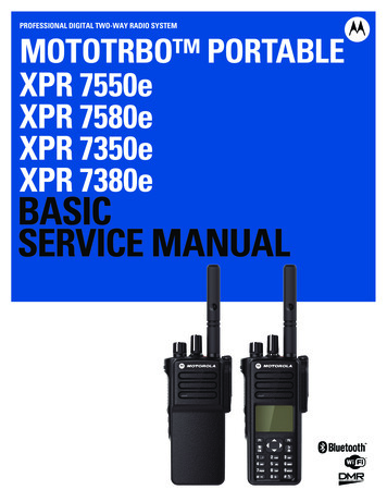
PROFESSIONAL DIGITAL TWO-WAY RADIO SYSTEMMOTOTRBO PORTABLEXPR 7550eXPR 7580eXPR 7350eXPR 7380eBASICSERVICE MANUALTM
iiiForewordThis manual covers all models of the XPR Series Portable Radios, unless otherwise specified. It includes all theinformation necessary to maintain peak product performance and maximum working time, using levels 1 and 2maintenance procedures. This level of service goes down to the board replacement level and is typical of some localservice centers, self-maintained customers, and distributors.Product Safety and RF Exposure Compliance!CautionBefore using this product, read the operating instructionsfor safe usage contained in the Product Safety and RFExposure booklet enclosed with your radio.For a list of Motorola-approved antennas, batteries, and other accessories, visit the following web site:http://www.motorolasolutions.comFor a list of Motorola TIA 4950 approved radio models, antennas, batteries, and other accessories,please refer to UL Safety manual MN001111A01 enclosed with your radio.TIA 4950The radio models listed in UL Safety Manual MN001111A01, when properly equip with the battery PMNN4489 , is certifiedfor use per the classification below: Classification Rating Division 1, Class I, Groups C, D; Class II Group E, F, G; Class III. T3C.Tamb -25 C to 60 C. Classification Rating Division 2, Class I, Groups A, B, C, D.Repairs of Motorola TIA 4950 certified intrinsically safe radios mustmust be carried out ONLY by Motorola I.S. trained personnel, who areaware of the special parts required and the procedures necessary tomaintain the TIA 4950 conformance of the product. The Motorolainternal service centres undergo regular training and receive aMotorola internal certification that enables them to conduct TIA 4950repairs.Computer Software CopyrightsThe Motorola products described in this manual may include copyrighted Motorola computer programs stored insemiconductor memories or other media. Laws in the United States and other countries preserve for Motorola certainexclusive rights for copyrighted computer programs, including, but not limited to, the exclusive right to copy or reproduce inany form the copyrighted computer program. Accordingly, any copyrighted Motorola computer programs contained in theMotorola products described in this manual may not be copied, reproduced, modified, reverse-engineered, or distributed inany manner without the express written permission of Motorola. Furthermore, the purchase of Motorola products shall notbe deemed to grant either directly or by implication, estoppel, or otherwise, any license under the copyrights, patents orpatent applications of Motorola, except for the normal non-exclusive license to use that arises by operation of law in thesale of a product.Document CopyrightsNo duplication or distribution of this document or any portion thereof shall take place without the express written permissionof Motorola. No part of this manual may be reproduced, distributed, or transmitted in any form or by any means, electronicor mechanical, for any purpose without the express written permission of Motorola.
ivDisclaimerThe information in this document is carefully examined, and is believed to be entirely reliable. However, no responsibility isassumed for inaccuracies. Furthermore, Motorola reserves the right to make changes to any products herein to improvereadability, function, or design. Motorola does not assume any liability arising out of the applications or use of any productor circuit described herein; nor does it cover any license under its patent rights nor the rights of others.TrademarksMOTOROLA, MOTO, MOTOROLA SOLUTIONS and the Stylized M logo are trademarks or registered trademarks ofMotorola Trademark Holdings, LLC and are used under license. All other trademarks are the property of their respectiveowners. 2016 Motorola Solutions, Inc.All rights reserved.
vDocument HistoryThe following major changes have been implemented in this manual since the previous edition:EditionMN002178A01-AADescriptionInitial ReleaseDateJan. 2016
viNotes
Table of ContentsviiTable of ContentsForeword .iiiProduct Safety and RF Exposure Compliance . iiiTIA 4950 . iiiComputer Software Copyrights . iiiDocument Copyrights . iiiDisclaimer.ivTrademarks .ivDocument History . vCommercial Warranty .xvLimited Warranty .xvMOTOROLA COMMUNICATION PRODUCTS .xvI. What This Warranty Covers And For How Long .xvII. General Provisions . xviIII. State Law Rights . xviIV. How To Get Warranty Service . xviV. What This Warranty Does Not Cover. xviVI. Patent And Software Provisions . xviiVII. Governing Law. xviiBattery and Charger Warranty .xviiiWorkmanship Warranty . xviiiCapacity Warranty . xviiiChapter 11.11.21.31.41.5Notations Used in This Manual . 1-1Radio Description . 1-11.2.1 Full Keypad Model. 1-21.2.2 Non Keypad Model . 1-4Portable Radio Model Numbering Scheme . 1-5Model Charts . 1-61.4.1 VHF Model Chart. 1-61.4.2 UHF Model Chart. 1-71.4.3 800/900 MHz Model Chart. 1-8Specifications. 1-9Chapter 22.12.2Introduction . 1-1Test Equipment and Service Aids . 2-1Recommended Test Equipment . 2-1Service Aids . 2-2
viiiTable of Contents2.3Programming, Testing and Alignment Cable . 2-3Chapter 33.13.23.33.4General . 3-1Setup. 3-1Display Model Test Mode . 3-43.3.1 Entering Display Radio Test Mode . 3-43.3.2 LCD Flicker Test Mode . 3-43.3.3 LCD Display Test Mode. 3-43.3.4 RF Test Mode . 3-53.3.5 LED Test Mode. 3-103.3.6 Accelerometer Test. 3-103.3.7 Backlight Test Mode . 3-103.3.8 Speaker Tone Test Mode . 3-103.3.9 Earpiece Tone Test Mode . 3-103.3.10 Audio Loopback Earpiece Test Mode. 3-103.3.11 Battery Check Test Mode . 3-113.3.12 Button/Knob/PTT Test Mode . 3-11Non-Display Model Test Mode. 3-133.4.1 Entering Non-Display Radio Test Mode . 3-133.4.2 RF Test Mode . 3-133.4.3 LED Test Mode. 3-133.4.4 Speaker Tone Test Mode . 3-133.4.5 Earpiece Tone Test Mode . 3-143.4.6 Audio Loopback Earpiece Test Mode. 3-143.4.7 Battery Check Test Mode . 3-143.4.8 Button/Knob/PTT Test Mode . 3-14Chapter 44.14.24.34.44.55.35.45.55.6Radio Programming and Tuning . 4-1Introduction . 4-1Customer Programming Software Setup . 4-1AirTracer Application Tool. 4-2Radio Tuning Setup . 4-2RF Adaptor Assembly . 4-3Chapter 55.15.2Transceiver Performance Testing . 3-1Disassembly/Reassembly Procedures . 5-1Introduction . 5-1Preventive Maintenance . 5-15.2.1 Inspection . 5-15.2.2 Cleaning Procedures . 5-1Safe Handling of CMOS and LDMOS Devices . 5-2Repair Procedures and Techniques – General. 5-4Disassembling and Reassembling the Radio — General . 5-5Radio Disassembly – Detailed . 5-65.6.1 Front Cover from Chassis Disassembly . 5-65.6.2 Chassis Disassembly. 5-105.6.3 Interface Board, Keypad Board and LCD Disassembly. 5-145.6.4 Speaker and Universal Connector Flex Disassembly. 5-17
Table of Contents5.75.85.95.6.5 Emergency Button Assembly Dissassembly . 5-195.6.6 Bluetooth GPS Antenna Disassembly . 5-20Radio Reassembly - Detailed . 5-215.7.1 Bluetooth GPS Antenna and Emergency Button Reassembly . 5-215.7.2 Speaker and Universal Connector Flex Reassembly . 5-225.7.3 Interface Board, Keypad Board and LCD Reassembly . 5-245.7.4 Chassis Reassembly . 5-265.7.5 Chassis and Front Cover Reassembly . 5-29Ensuring Radio Immersibility . 5-305.8.1 Servicing. 5-305.8.2 Accidental Immersion . 5-305.8.3 Specialized Test Equipment . 5-305.8.4 Vacuum Pump Kit NLN9839. 5-305.8.5 Pressure Pump Kit NTN4265 . 5-315.8.6 Miscellaneous Hardware . 5-315.8.7 Vacuum Test . 5-315.8.8 Pressure Test . 5-325.8.9 Troubleshooting Leak Areas. 5-335.8.9.1 Front Housing . 5-335.8.9.2 Battery Contact Seal. 5-345.8.9.3 Air Ventilation Label. 5-355.8.9.4 Battery Maintenance. 5-355.8.10 Troubleshooting Charts . 5-36Radio Exploded Mechanical Views and Parts Lists . 5-395.9.1 Full Keypad Model Exploded View and Parts List . 5-395.9.2 Non Keypad Model Exploded View and Parts List . 5-425.9.3 Torque Chart . 5-47Chapter 66.16.26.36.4Basic Troubleshooting . 6-1Introduction . 6-1Replacement Back Cover Kit Procedures . 6-1Power-Up Error Codes (Display Model only) . 6-2Operational Error Codes . 6-4Chapter 77.1ixAccessories . 7-1Introduction . 7-17.1.1 Batteries . 7-17.1.2 Antennas . 7-27.1.3 Carry Devices . 7-27.1.4 CPS . 7-37.1.5 Miscellaneous Accesories . 7-3Appendix A Replacement Parts Ordering.A-1A.1A.2A.3A.4A.5Basic Ordering Information .A-1Motorola Online .A-1Mail Orders .A-1Telephone Orders .A-1Fax Orders .A-1
xTable of ContentsA.6A.7Parts Identification .A-2Product Customer Service .A-2Appendix B Motorola Service Centers.B-1B.1B.2B.3B.4Servicing Information .B-1Motorola Service Center .B-1Motorola Canadian Technical Logistics Center .B-1Motorola Federal Technical Center.B-1Appendix C Limited Level 3 Servicing .C-1C.1C.2C.3Maintenance . C-1Chip Components . C-1Component and Parts list. C-2Glossary . Glossary-1
List of FiguresxiList of FiguresFigure 1-1.Figure 1-2.Figure 1-3.Figure 2-1.Figure 2-2.Figure 3-1.Figure 3-2.Figure 4-1.Figure 4-2.Figure 4-3.Figure 4-4.Figure 4-5.Figure 4-6.Figure 5-1.Figure 5-2.Figure 5-3.Figure 5-4.Figure 5-5.Figure 5-6.Figure 5-7.Figure 5-8.Figure 5-9.Figure 5-10.Figure 5-11.Figure 5-12.Figure 5-13.Figure 5-14.Figure 5-15.Figure 5-16.Figure 5-17.Figure 5-18.Figure 5-19.Figure 5-20.Figure 5-21.Figure 5-22.Figure 5-23.Figure 5-24.Figure 5-25.Figure 5-26.Figure 5-27.Figure 5-28.Figure 5-29.Figure 5-30.Figure 5-31.Figure 5-32.Figure 5-33.Figure 5-34.Figure 5-35.Figure 5-36.Figure 5-37.Full Keypad Model . 1-2Non Keypad Model. 1-4Portable Radio Model Numbering Scheme. 1-5Programming, Testing and Alignment Cable. 2-3Pin Layout of Side Connector . 2-4DMR Radio Transmitter and Receiver Testing Setup . 3-3Battery Check Test Mode Display . 3-11CPS Programming Setup. 4-1Radio Tuning Equipment Setup . 4-2RF Plug removal . 4-3RF Adaptor holder. 4-3RF Adaptor screw . 4-4RF Adaptor complete assembly . 4-4Battery removal . 5-6Antenna removal. . 5-6Shroud removal. 5-7Chassis removal . 5-7Chassis and Front Housing. 5-8Keypad flex removal. 5-8Interface flex removal. 5-9GOB and mini GOB flex removal . 5-10Mainboard removal . 5-10Top control seal removal . 5-11GOB removal . 5-11Battery contact seal removal. 5-12RF rubber plug removal . 5-12Interface flex removal. 5-14UC flex removal . 5-14PTT flex removal . 5-15Interface board removal . 5-15Keypad board removal . 5-16Display module removal. 5-16UC escutcheon removal. 5-17UC flex removal . 5-17Speaker assembly removal . 5-18Speaker removal . 5-18Emergency button removal . 5-19Bluetooth GPS antenna removal . 5-20Bluetooth GPS antenna reassembly . 5-21Emergency button reassembly. 5-21Speaker retainer reassembly . 5-22Speaker reassembly . 5-22UC Escutcheon replacement . 5-23Display module reassembly . 5-24Keypad Board reassembly . 5-24Front housing reassembly. 5-25Chassis reassembly . 5-26Thermal Pad . 5-26Top control seal reassembly. 5-27Main board and GOB reassembly. 5-28
xiiList of FiguresFigure 5-38.Figure 5-39.Figure 5-40.Figure 5-41.Figure 5-42.Figure C-1.Figure C-2.Main board connectors. 5-29Chassis reassembly . 5-29Connector Fitting - Fitting Seal Pump Connector. 5-30Full Keypad Model Exploded View. 5-39Non Keypad Exploded View. 5-42PCB Top View . C-2PCB Bottom View. C-2
List of TablesxiiiList of TablesTable 1-1.Table 2-1.Table 2-2.Tabl
The Motorola products described in this manual may include copyrighted Motorola computer programs stored in semiconductor memories or other media. Laws in the United States and other countries preserve for Motorola certain exclusive rights for copyrighted computer programs, including, but no

