Transcription
USER GUIDENI myDAQFrançaisDeutschni.com/manualsNI myDAQ is a low-cost portable data acquisition (DAQ) device that uses NI LabVIEW-basedsoftware instruments, allowing students to measure and analyze real-world signals. NI myDAQis ideal for exploring electronics and taking sensor measurements. Combined with NI LabVIEWon the PC, students can analyze and process acquired signals and control simple processesanytime, anywhere.Figure 1. NI myDAQNI myDAQPower SupplyUSBCurrentLimiterDC-toDCConverter 15 V5VSystem TimingControllerDigital Input/OutputDIOGainiplexerAnalog InputAIMultAnalogto-DigitalConverterAnalog OutpuDigitalMultimeterVΩAUDIO INtSwitchDigitalto-AnalogConverterAOAUDIO OUTANI myDAQSystem DiagramAnalogsupplied ICsbyVΩAHI60 V20 VrmsMAXCOM1AMAXHIContentsSafety Information . 2Electromagnetic Compatibility Guidelines . 3NI myDAQ Hardware Overview. 3Analog Input (AI) . 4Analog Output (AO) . 5Digital Input/Output (DIO). 5Power Supplies . 5Digital Multimeter (DMM) . 6NI myDAQ Software Overview . 6NI ELVISmx Driver Software. 6NI LabVIEW and NI ELVISmx Express VIs . 6NI myDAQ and NI Multisim. 7Getting Started . 7
Making Signal Connections with NI myDAQ. 7Setting up Your NI myDAQ Device. 7Connecting Signals . 9Connecting Analog Input Signals . 11NI myDAQ DMM Fuse Replacement . 13Digital I/O (DIO) and Counters/Timers. 16Using NI myDAQ with NI ELVISmx Software Instruments. 16NI ELVISmx Instrument Launcher . 17Digital Multimeter (DMM). 18Oscilloscope (Scope) . 19Function Generator (FGEN) . 20Bode Analyzer . 21Dynamic Signal Analyzer (DSA) . 22Arbitrary Waveform Generator (ARB). 23Digital Reader . 24Digital Writer . 25Example: Measuring a Signal Using the NI ELVISmx Oscilloscopewith NI myDAQ . 26Using NI myDAQ with LabVIEW . 27NI ELVISmx Express VIs in LabVIEW. 27Example: Measuring Signals Using the NI ELVISmx Oscilloscope Express VIwith NI myDAQ . 28Using NI-DAQmx with NI myDAQ . 30Example: Measuring Audio Pass-Through in LabVIEW with NI myDAQ . 30Texas Instruments Components in NI myDAQ. 34Resource Conflicts . 35Additional Resources . 37Related Documentation. 37Other Resources . 37Common Terms and Acronyms. 38Warranty . 39Worldwide Support and Services . 39Safety InformationDo not operate the hardware in a manner not specified in this documentand in the user documentation. Misuse of the hardware can result in a hazard. Youcan compromise the safety protection if the hardware is damaged in any way. If thehardware is damaged, return it to National Instruments for repair.CautionClean the hardware with a soft, nonmetallic brush. Make sure that the hardware is completelydry and free from contaminants before returning it to service.2 ni.com NI myDAQ User Guide
Electromagnetic Compatibility GuidelinesCautionsTo ensure the specified EMC performance: The USB cable must be less than 2.0 m (6.6 ft) in length. The length of any wire or cable connected to the 20-pin screw terminalconnector must be no longer than 0.3 m (1 ft). The length of any wire or cable connected to the Audio or DMM ports must beno longer than 3 m (10 ft).This product was tested and complies with the regulatory requirements and limits forelectromagnetic compatibility (EMC) as stated in the product specifications. These requirementsand limits are designed to provide reasonable protection against harmful interference when theproduct is operated in its intended operational electromagnetic environment.This product is intended for use in residential, commercial, and industrial locations. There is noguarantee that harmful interference will not occur in a particular installation or when the productis connected to a test object. To minimize the potential for the product to cause interference toradio and television reception or to experience unacceptable performance degradation, installand use this product in strict accordance with the instructions in the product documentation.Furthermore, any changes or modifications to the product not expressly approved by NationalInstruments could void your authority to operate it under your local regulatory rules.NI myDAQ Hardware OverviewNI myDAQ provides analog input (AI), analog output (AO), digital input and output (DIO),audio, power supplies, and digital multimeter (DMM) functions in a compact USB device.Tip The Common Terms and Acronyms section has a list of acronyms and termsthat you will see in this manual, and in many engineering and measurementdocuments and websites.NI myDAQ User Guide National Instruments 3
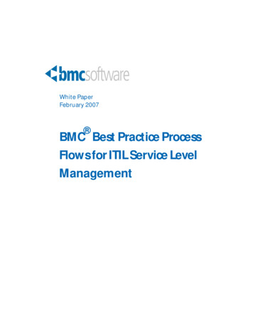
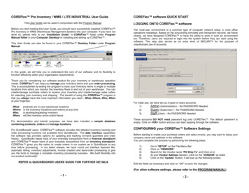
Integrated circuits supplied by Texas Instruments form the power and analog I/O subsystems ofNI myDAQ. Figure 2 depicts the arrangement and function of the NI myDAQ subsystems. Referto Table 5 for more information on all of the Texas Instruments components used in NI myDAQ.Figure 2. NI myDAQ Hardware Block Diagram 15 VUSB uit(TPS61170)–15 V(TPS2553)(CSD25302Q2) 5 V8DIO xRegulator(TPS62003)GainADC 1.2 9)ChannelMultiplexerRegulator(TPS62007) 3.3 VUSB-STC3DACOP AMP(DAC8551) 3.3 VAI 0 AI 0–AI 1 AI 1–Line In RLine In L(OPA1642)AO 0Switch(TS12A44514)OP erAO 1IsolationBarrier(ISO7241)Audio AMP(TPA6110A2)Line Out RLine Out Register(SN74AHC595)Isolated 3.3 VDMMIsolated 5 VSwitch(TS5A3159)HICOM HI(V Ω)(A)Note: NI myDAQ components may be changed or substituted without notice.Analog Input (AI)There are two analog input channels on NI myDAQ. These channels can be configured either asgeneral-purpose high-impedance differential voltage input or audio input. The analog inputs aremultiplexed, meaning a single analog-to-digital converter (ADC) is used to sample bothchannels. In general-purpose mode, you can measure up to 10 V signals. In audio mode, thetwo channels represent left and right stereo line level inputs. Analog inputs can be measured atup to 200 kS/s per channel, so they are useful for waveform acquisition. Analog inputs are usedin the NI ELVISmx Oscilloscope, Dynamic Signal Analyzer, and Bode Analyzer instruments.4 ni.com NI myDAQ User Guide
Analog Output (AO)There are two analog output channels on NI myDAQ. These channels can be configured as eithergeneral-purpose voltage output or audio output. Both channels have a dedicateddigital-to-analog converter (DAC), so they can update simultaneously. In general-purposemode, you can generate up to 10 V signals. In audio mode, the two channels represent left andright stereo outputs.Caution If using earphones to listen to the audio output of the NI myDAQ, ensurethat the volume is set to a safe level. Listening to audio signals at a high volume mayresult in permanent hearing loss.Note The myDAQ supports output on either a 10 V or 2 V range and outputfrom either one or both AO channels. When outputting from both AO channels,however, they must share a common voltage range.Creating a task on an AO channel will set the range for both channels. Ifa task that was previously running is stopped and a new task is created using thesecond AO channel set to a different output range, the output on the original channelwill scale based on the range of the new task.CautionAnalog outputs can be updated at up to 200 kS/s per channel, making them useful for waveformgeneration. Analog outputs are used in the NI ELVISmx Function Generator, ArbitraryWaveform Generator, and Bode Analyzer instruments.Digital Input/Output (DIO)There are eight DIO lines on NI myDAQ. Each line is a Programmable Function Interface (PFI),meaning that it can be configured as a general-purpose software-timed digital input or output, orit can act as a special function input or output for a digital counter. Refer to Digital I/O (DIO)and Counters/Timers section for more information about the counter on NI myDAQ.Note The digital I/O lines are 3.3 V LVTTL and are tolerant to 5 V inputs. Thedigital output is not compatible with 5 V CMOS logic levels.Power SuppliesThere are three power supplies available for use on NI myDAQ. 15 V and -15 V can be usedto power analog components such as operational amplifiers and linear regulators. 5 V can beused to power digital components such as logic devices.The total power available for the power supplies, analog outputs, and digital outputs is limitedto 500 mW (typical)/100 mW (minimum). To calculate the total power consumption of thepower supplies, multiply the output voltage by the load current for each voltage rail and sumthem together. For digital output power consumption, multiply 3.3 V by the load current. Foranalog output power consumption, multiply 15 V by the load current. Using audio outputsubtracts 100 mW from the total power budget.NI myDAQ User Guide National Instruments 5
For example, if you use 50 mA on 5 V, 2 mA on 15 V, 1 mA on -15 V, use four DIO lines todrive LEDs at 3 mA each, and have a 1 mA load on each AO channel, the total output powerconsumption is:5 V 50 mA 250 mW 15 V 2 mA 30 mW -15 V 1 mA 15 mW3.3 V 3 mA 4 39.6 mW15 V 1 mA 2 30 mWTotal output power consumption 250 mW 30 mW 15 mW 39.6 mW 30 mW 364.6 mWDigital Multimeter (DMM)The NI myDAQ DMM provides the functions for measuring voltage (DC and AC), current(DC and AC), resistance, and diode voltage drop.DMM measurements are software-timed, so update rates are affected by the load on thecomputer and USB activity.NI myDAQ Software OverviewNI ELVISmx Driver SoftwareNI ELVISmx is the driver software that supports NI myDAQ. NI ELVISmx usesLabVIEW-based software instruments to control the NI myDAQ device, providing thefunctionality of a suite of common laboratory instruments. Refer to the Using NI myDAQ withNI ELVISmx Software Instruments section for information on the NI ELVISmx suite ofmeasurement instruments.NI ELVISmx is located on your driver software installation media included in the NI myDAQkit, or can be found by searching for ELVISmx on the Drivers and Updates page at ni.com/drivers. To determine the version of NI ELVISmx software support required for your versionof LabVIEW, go to ni.com/info and enter the Info Code ELVISmxsoftware.NI LabVIEW and NI ELVISmx Express VIsAlso installed with NI ELVISmx are the LabVIEW Express VIs, which use NI ELVISmxsoftware instruments to program NI myDAQ with more enhanced functionality. For moreinformation on the NI ELVISmx Express VIs, refer to the Using NI myDAQ with LabVIEWsection.Note NI ELVISmx supports LabVIEW (32 bit). To use NI ELVISmx withLabVIEW on a 64-bit operating system, you must have LabVIEW (32 bit) installed.6 ni.com NI myDAQ User Guide
NI myDAQ and NI MultisimYou can use NI ELVISmx instruments in NI Multisim to simulate a circuit, measure the realsignals with NI myDAQ, and compare simulated and acquired data. For more information on thefeatures and resources available with NI Multisim, visit ni.com/multisim.Getting StartedGetting started with NI myDAQ is a simple process, but it is important to ensure that you installthe right components in the correct order. To get started with your NI myDAQ, complete thefollowing steps:1.Install the NI myDAQ Software Suite from the DVD shipped with your device.The NI myDAQ Software Suite installs application software (NI LabVIEW, NI Multisim)first, and then installs the NI ELVISmx driver software.Note If you are not installing software from the NI myDAQ Software Suite media,make sure to install all application software before installing the driver software.2.Connect the cable from the computer Hi-Speed USB port to the USB port on the device.The computer will recognize the NI myDAQ and the NI ELVISmx Instrument Launcherappears. You can also manually open NI ELVISmx Instrument Launcher by selectingStart»All Programs»National Instruments»NI ELVISmx for NI ELVIS &NI myDAQ»NI ELVISmx Instrument Launcher.To ensure the specified EMC performance, the USB cable must be lessthan 2.0 m (6.6 ft) in length.CautionMaking Signal Connections with NI myDAQSetting up Your NI myDAQ DeviceCaution Insert and remove the 20-position screw terminal connector alignedevenly to the NI myDAQ. Inserting the screw terminal connector at an angle to theNI myDAQ may cause damage to the connector.The screw terminal connector must snap securely into place to ensure proper signalconnection.NI myDAQ User Guide National Instruments 7
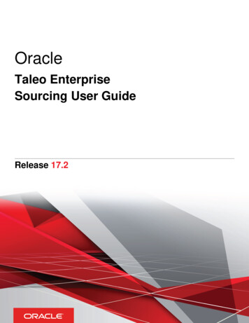
Figure 3. NI myDAQ Connection Diagram213NI myDAQPower SupplyUSBCurrentLimiterDC-toDCConverter 15 V5VSystem TimingControllerDigital Input/OutputDIOAnalog InputGainAIAUDIO IN4Analog eterVΩMultiplexerAnalogto-DigitalConverterAOAUDIO OUTANI myDAQSystem DiagramAnalogsupplied ICsbyVΩAHI60 V20 VrmsMAXCOM1AMAXHI561238NI myDAQUSB CableLED ni.com 456NI myDAQ User Guide20-Position Screw Terminal ConnectorAudio CableDMM Banana Cable
Connecting SignalsFigure 4 shows the available audio, AI, AO, DIO, GND, and power signals accessed through the3.5 mm audio jacks and screw terminal connections. Refer to Table 1 for descriptions of thesesignals.Signal wires must be securely affixed and screwed down in the screwterminal connector to ensure proper connection.CautionsTo ensure the specified EMC performance: The length of any wire or cable connected to the 20-pin screw terminalconnector must be no longer than 0.3 m (1 ft). The length of any wire or cable connected to the Audio or DMM ports must beno longer than 3 m (10 ft).DIO 0/PFI 0/CTR 0 SOURCEDIO 1/PFI 1/CTR 0 GATEDIO 2/PFI 2/CTR 0 AUXDIO 3/PFI 3/CTR 0 OUTDIO 4/PFI 4/FREQ OUTFigure 4. NI myDAQ 20-Position Screw Terminal I/O ConnectorAUDIOINAUDIOOUTTable 1. Screw Terminal Signal DescriptionsSignal NameReferenceDirectionAUDIO IN—InputAUDIO OUT—OutputAudio Output—Left and right audiooutputs on a stereo connectorAGNDOutput 15 V/-15 V power supplies——AO 0/AO 1AGNDOutputAI 0 /AI 0-;AI 1 /AI 1-AGNDInput 15V/-15VAGNDDescriptionAudio Input—Left and right audioinputs on a stereo connectorAnalog Ground—Reference terminalfor AI, AO, 15 V, and -15 VAnalog Output Channels 0 and 1*Analog Input Channels 0 and 1NI myDAQ User Guide National Instruments 9
Table 1. Screw Terminal Signal Descriptions (Continued)Signal NameReferenceDirectionDGNDInput orOutputDGND——Digital Ground—Reference for the DIOlines and the 5 V supplyPFI 0/CTR 0 SOURCE——Digital I/O, line 0; PFI 0, Defaultfunction: Counter 0 SourcePFI 1/CTR 0 GATE——Digital I/O, line 1; PFI 1, Defaultfunction: Counter 0 GatePFI 2/CTR 0 AUX——Digital I/O, line 2; PFI 2, Defaultfunction: Counter 0 AuxPFI 3/CTR 0 OUT——Digital I/O, line 3; PFI 3, Defaultfunction: Counter 0 OutPFI 4/FREQ OUT——Digital I/O, line 4; PFI 4, Defaultfunction: Frequency OutputDGNDOutputDIO 0.7 5VDescriptionDigital I/O Signals—General-purposedigital lines or counter signals5 V power supply* The myDAQ supports output on either a 10 V or 2 V range and output from either one or both AO channels.When outputting from both AO channels, however, they must share a common voltage range.Figure 5 shows the DMM connections on the NI myDAQ. Table 2 describes these signals.60 VDC/20 Vrms maximum. Do not plug digital multimeter probes intocircuits with Hazardous Voltages, such as wall outlets.CautionFigure 5. Connections for DMM MeasurementsHI121012VΩA600V20 VrmsMAXCOMConnectors for Voltage/Resistance/Diode/ContinuityConnectors for Current ni.com NI myDAQ User Guide1AMAXHI
Table 2. DMM Signal M——HI (A)COMInputHI (VΩ)DescriptionPositive terminal for voltage, resistance,and diode measurementsReference for all DMM measurementsPositive terminal for current measurements(Fused: F 1.25 A 250 V Fast-Acting)Connecting Analog Input SignalsWhen configuring the input channels and making signal connections, you must first determinewhether the signal sources are floating or ground referenced. The following sections describethese two signal types.Ground-Referenced Signal SourcesA ground-referenced signal source is connected to the building system ground, so it is alreadyconnected to a common ground point with respect to the NI myDAQ device, assuming that thecomputer is plugged into the same power system. Instruments or devices with nonisolatedoutputs that plug into the building power system are ground-referenced signal sources.Note Most laptop computers have isolated power supplies, and are consequentlynot connected to the building ground system. In these cases, treat the analog inputsignal as floating with respect to NI myDAQ.The difference in ground potential between two instruments connected to the same building powersystem is typically between 1 and 100 mV. This difference can be much higher if powerdistribution circuits are improperly connected. If a grounded signal source is improperly measured,this difference might appear as a measurement error. Connect the differential analog inputs acrossthe signal source and do not connect the NI myDAQ AGND pin to the grounded source.Figure 6. Ground-Referenced Differential ConnectionSignal SourceAI –AI– –AGNDNI myDAQ User Guide National Instruments 11
Floating Signal SourcesA floating signal source is not connected to the same ground reference as NI myDAQ, butinstead has an isolated reference point. Some examples of floating signal sources arebattery-powered devices, outputs of transformers, thermocouples, optical isolator outputs, andisolation amplifiers. An instrument or device that has an isolated output is a floating signalsource. You must connect the ground reference of a floating signal to an NI myDAQ AGND pinthrough a bias resistor or jumper wire to establish a local or onboard reference for the signal.Otherwise, the measured input signal varies as the source floats out of the common-mode inputrange.The easiest way to reference the source to AGND is to connect the positive side of the signal toAI and connect the negative side of the signal to AGND as well as to AI- without usingresistors. This connection works well for DC-coupled sources with low source impedance (lessthan 100 Ω).Figure 7. Differential Connections for Floating Signal Sources without ResistorsSignal SourceAI –AI–Rsource 100 Ω –AGNDFor larger source impedances, however, this connection leaves the differential signal pathsignificantly off balance. Noise that couples electrostatically onto the positive line does notcouple onto the negative line because it is connected to ground. This noise appears as adifferential-mode signal instead of a common-mode signal, and thus appears in your data. In thiscase, instead of directly connecting the negative line to AGND, connect the negative line toAGND through a resistor that is about 100 times the equivalent source impedance. The resistorputs the signal path nearly in balance, so that about the same amount of noise couples onto bothconnections, yielding better rejection of electrostatically coupled noise. This configuration doesnot load down the source.Figure 8. Differential Connections for Floating Signal Sources with a Single ResistorSignal SourceAI –Rsource 100 Ω12 ni.com NI myDAQ User GuideAI– –AGND
You can fully balance the signal path by connecting another resistor of the same value betweenthe positive input and AGND, as shown in Figure 9. This fully balanced configuration offersslightly better noise rejection, but has the disadvantage of loading the source down with theseries combination (sum) of the two resistors. If, for example, the source impedance is 2 kΩ andeach of the two resistors is 100 kΩ, the resistors load down the source with 200 kΩ and producea -1% gain error.Figure 9. Differential Connections for Floating Signal Sources with Two ResistorsSignal SourceAI –AI–Rsource 100 Ω –AGNDBoth positive and negative analog input lines require a DC path to ground in order for theinstrumentation amplifier to work. If the source is AC coupled (capacitively coupled), a resistoris needed between the positive input and AGND. If the source has low impedance, choose aresistor that is large enough not to significantly load the source but small enough not to producesignificant input offset voltage as a result of input bias current (typically 100 kΩ to 1 MΩ). Inthis case, connect the negative input directly to AGND. If the source has high output impedance,balance the signal path as previously described using the same value resistor on both the positiveand negative inputs.NI myDAQ DMM Fuse ReplacementNI myDAQ has a fuse to protect the device from overcurrent through HI (A) currentmeasurement input on the DMM. If the NI ELVISmx DMM software instrument always reads0 A current, the cause may be a blown fuse.Testing Your FuseTo test for a blown fuse, complete the following steps.1.Using a banana cable, connect the HI (V) and HI (A) DMM terminals.2.Launch the NI ELVISmx Digital Multimeter (DMM) software instrument from theNI ELVISmx Instrument Launcher, located at Start»All Programs»NationalInstruments»NI ELVISmx for NI ELVIS & NI myDAQ»NI ELVISmx InstrumentLauncher.3.Select the Resistance mode by clicking the Resistance button.4.Click Run.5.If the fuse is blown, the display will show Over, indicating a disconnected circuit path.Replace the fuse and complete the procedure again.NI myDAQ User Guide National Instruments 13
Replacing the FuseReplace broken fuses with a 1.25 A Fast-Acting sand-filled 5 20 mm fuse (Littelfuse partnumber 02161.25 at www.littelfuse.com).To replace a broken fuse, complete the following steps.1.Power down the device by properly disconnecting it from the PC and removing the USBcable.2.Remove the screw terminal connector and all other signal cables from the device.3.Loosen the four Phillips screws that attach the bottom of the enclosure to the device, andremove the top lid of the enclosure.CautionDo not remove the board from the bottom half of the NI myDAQenclosure.14 ni.com NI myDAQ User Guide
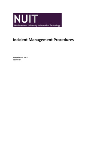
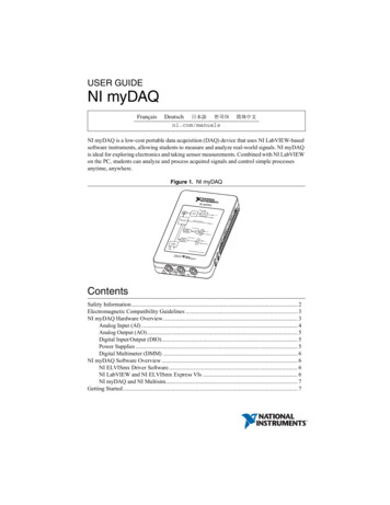
4.Replace the broken fuse while referring to Figure 10 for the fuse location, taking care to notdamage any components on the board.Figure 10. NI myDAQ Fuse LocationNI myNImyDDAAQQPower SupplyUSBCurrentLimiterDC-toDCConverter 15 V5VSystem TiminController gDigital Input/OutputDIOtiplexerAnalog alMultimeterVΩAUDIO INAnalog OutputDigitalto-AnalogConverterAOAUDIO OUTANI myDAQSystem DiagramAnalogsupplied ICsbyVΩAHI1125.60 V20 VrmsMAXCOM1AMAXHI21Enclosure ScrewsInternal Fuse—1.25 A Fast-Acting (Littelfuse Part Number 02161.25)Replace the lid and screws.NI myDAQ User Guide National Instruments 15
Digital I/O (DIO) and Counters/TimersThere are eight, software-timed DIO lines on the NI myDAQ that can be individually configuredfor input or output. Additionally, lines DIO 0.4 can be configured for counter/timerfunctionality. The input—accessed through DIO 0, DIO 1, and DIO 2 signals configured as acounter—is used for counter, timer, pulse width measuring, and quadrature encodingapplications.When using the counter/timer, the Source is accessed through DIO 0, the Gate through DIO 1,the Auxiliary Input through DIO 2, the Output through DIO 3, and the Frequency Outputthrough DIO 4. When using the counter/timer as a quadrature encoder, A, Z, and B correspondto DIO 0, DIO 1, and DIO 2, respectively. In some instances, the software may refer to theoutput lines as PFI as opposed to DIO. Refer to Table 3 for a list of the correspondingcounter/timer signals assignments through the DIO terminals.Table 3. NI myDAQ Counter/Timer Signal AssignmentsNI myDAQSignalProgrammableFunction Interface(PFI)Counter/TimerSignalQuadrature EncoderSignalDIO 0PFI 0CTR 0 SOURCEADIO 1PFI 1CTR 0 GATEZDIO 2PFI 2CTR 0 AUXBDIO 3*PFI 3CTR 0 OUT—DIO 4PFI 4FREQ OUT—*DIO 3 can be used to generate pulse-width modulation (PWM) signals.For more information about event timing requirements, refer to the NI myDAQ Specificationsdocument. For more detailed information on using counter/timers with NI myDAQ, refer to theKnowledgeBase document How Do I Use the NI myDAQ Counter?. To access this document,go to ni.com/info and enter the Info Code mydaqcounter.Using NI myDAQ with NI ELVISmx SoftwareInstrumentsBefore opening an NI ELVISmx software instrument, make sure that themyDAQ device is connected to the system and is ready to use. After the myDAQ isconnected to the system, the blue LED by the connector lights, indicating the deviceis ready for use. The NI ELVISmx Instrument Launcher then launches automatically.Note16 ni.com NI myDAQ User Guide
NI ELVISmx provides a collection of software instruments, created in LabVIEW, and the sourcecode for the instruments. You cannot directly modify the executable files, but you can modify orenhance the functionality of these instruments by modifying the LabVIEW code, which installsin the following directory: C:\Users\Public\Public Documents\NationalInstruments\NI ELVISmx Source CodeFor a detailed explanation of the NI ELVISmx software instruments,instructions for taking a measurement with each instrument, and information on theother NI ELVISmx Instrument Launcher features, refer to the NI ELVISmx Help. Toaccess this help file, click the NI ELVISmx Help icon on the Resources tab of theNI ELVISmx Instrument Launcher.NoteNI ELVISmx Instrument LauncherThe NI ELVISmx Instrument Launcher provides access to the NI ELVISmx softwareinstruments, additional featured instruments, lab exercises, documentation and online resourcelinks, and functionality to add data and reference files. To open the Instrument Launcher,navigate to Start»All Programs»National Instruments»NI ELVISmx for NI ELVIS &NI myDAQ»NI ELVISmx Instrument Launcher. This opens the suite of NI ELVISmxsoftware instruments.Figure 11. NI ELVISmx Instrument LauncherTo launch an instrument, click the button corresponding to the desired instrument. Select theNI myDAQ device from the Device control pull-down dialog.Some instruments perform similar operations using the same resources of the NI myDAQhardware and therefore cannot run at the same time. If you launch two instruments withove
USER GUIDE NI myDAQ NI myDAQ is a low-cost portable data acquisition (DAQ ) device that uses NI LabVIEW-based . hardware is damaged, return it to National Instruments for repair. Clean the hardware with a soft, nonmetallic brush. Make sure that the hardware is completely . compu