Transcription
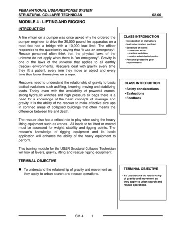
FEMA NATIONAL US&R RESPONSE SYSTEMSTRUCTURAL COLLAPSE TECHNICIAN02-00MODULE 4 - LIFTING AND RIGGINGINTRODUCTIONA fire officer on a pumper was once asked why he ordered thepumper engineer to drive the 30,000 pound fire apparatus on aroad that had a bridge with a 10,000 load limit. The officerresponded to the question by saying that "it was an emergency".Rescue personnel often think that the physical laws of theuniverse do not apply when there is "an emergency". Gravity isone of the laws of the universe that applies to all earthly(rescue) environments. Rescuers deal with gravity every timethey lift a patient, every time they move an object and everytime they lower themselves on a rope.CLASS INTRODUCTIONRescuers need to understand the relationship of gravity to basictactical evolutions such as lifting, lowering, moving and stabilizingloads. Today even with the availability of powerful cranes,strong hydraulic winches and high pressure air bags there is aneed for a knowledge of the basic concepts of leverage andgravity. It is the ability of the rescuer to make effective size upsin confined areas of collapsed buildings that often means thedifference between life and death.CLASS INTRODUCTION Introduction of instructors Instructor/student contract Schedule of events– classroom lecture– practical evolutions– rotation schedule/site location Personal protective gearrequirements Safety considerations Evaluations FeedbackThe rescuer also has a critical role to play when using the heavylifting equipment such as cranes. All loads to be lifted or movedmust be assessed for weight, stability and rigging points. Therescuer's knowledge of rigging equipment and its basicapplication will enhance the ability of the heavy equipment toperform.This training module for the US&R Sructural Collapse Technicianwill look at levers, gravity, lifting and rescue rigging equipment.TERMINAL OBJECTIVEn To understand the relationship of gravity and movement asthey apply to urban search and rescue operations.SM 41TERMINAL OBJECTIVE To understand the relationshipof gravity and movement asthey apply to urban search andrescue operations.
FEMA NATIONAL US&R RESPONSE SYSTEMSTRUCTURAL COLLAPSE TECHNICIAN02-00MODULE 4 - LIFTING AND RIGGINGENABLING OBJECTIVESAt the conclusion of module the student should be able to:n Understand the basic physics as they relate to mass, gravity,and center of gravity.n Understand moment of force considerations as the relate tothe movement of stationary objects.n Explain the concept of elasticity of solids.ENABLING OBJECTIVESAt the conclusion of module the studentshould be able to: Understand the basic physics as they relate tomass, gravity, and center of gravity. Understand moment of force considerations asthe relate to the movement of stationary objects. Explain the concept of elasticity of solids. Describe what determines the efficiency ofmechanical advantages. Explain the three classes of levers. Describe the efficiency of inclined planes.n Describe what determines the efficiency of mechanicaladvantages.n Explain the three classes of levers.n Describe the efficiency of inclined planes.ENABLING OBJECTIVESn Describe the two types of pulley configurations.n Explain the effective use of high pressure air bags.n Calculate the weights of common materials.n Explain the use of anchor systems, anchor failureconsiderations, and proper anchor spacing.At the conclusion of module the studentshould be able to: Describe the two types of pulley configurations. Explain the effective use of high pressure airbags. Calculate the weights of common materials. Explain the use of anchor systems, anchorfailure considerations, and proper anchorspacing. Describe the proper use of swivel hoist, steelangle brackets, and concrete screws. Understand the proper use of wire rope, wirerope fittings, end terminations, and tighteners.n Describe the proper use of swivel hoist, steel anglebrackets, and concrete screws.n Understand the proper use of wire ropes, wire rope fittings,end terminations, and tighteners.n Explain the use of slings and sling arrangements.n Describe the use of chains for rigging and lifting.n Determine the effects of critical angles as the relate to liftingand moving objects.n Identify and describe the advantages and disadvantages ofthe different types of cranes.n Explain considerations for crane use, and demonstrate basiccrane signals for rescue operationsSM 42ENABLING OBJECTIVESAt the conclusion of module the studentshould be able to: Explain the use of slings and sling arrangements. Describe the use of chains for rigging and lifting. Determine the effects of critical angles as therelate to lifting and moving objects. Identify and describe the advantages anddisadvantages of the different types of cranes. Explain considerations for all crane use. Demonstrate basic crane signals for rescueoperations.
FEMA NATIONAL US&R RESPONSE SYSTEMSTRUCTURAL COLLAPSE TECHNICIAN02-00MODULE 4 - LIFTING AND RIGGINGUNIVERSALGRAVITATIONUNIVERSAL GRAVITATION and CENTER of GRAVITYPRINCIPLEn Every particle in the universe attracts every other particlewith a force proportional to their combined mass, andinversely proportional to the square of the distance betweenthem. There is no exception to gravity.All objects seek a state of equilibrium.Gravity effects such evolutions as:- Lifting- Lowering- StabilizingGRAVITY EFFECTSSUCH EVOLUTIONS AS: Lifting Lowering Moving StabilizingCENTER OF GRAVITY (CG) AND POSITION CHANGESn Center of gravity: Point at which the whole weight of objectis acting vertically downward balance.n Load's weight is perfectly balanced or distributed around thecenter of gravity.n If a load is suspended at its CG, it can be turned in anydirection with little effort.n If load is lifted to the right/left of CG, it will tilt at an angle.n If a load is lifted below its center of gravity, the weight of theload will be above the lifting point, and the load will tip over.n Important that loads be hoisted above the load's CG.n CG of a solid object is located in three planes or directions: X axis Horizontal, side to sideY axis Vertical axisZ axis Horizontal, front to backEXAMPLE OF CG:A solid piece of concrete that is 10ft long x 4ft wide x 6ft highhas it’s CG at a point that is 5ft from the end, 2ft from the front,and 3ft from the bottomSM 43CENTER OF GRAVITY Point on a body around whichthe body’s mass is evenlydistributed. Point in a body where all theforces of the earth’sgravitational pull are equal.CENTER OF GRAVITY Center is at the junction of three axis.– X-axis Horizontal, side to side– Y-axis Vertical– Z-axis Horizontal, front to backYZXXYZCENTER OF GRAVITYLIFTING POINTCGCG
FEMA NATIONAL US&R RESPONSE SYSTEMSTRUCTURAL COLLAPSE TECHNICIAN02-00MODULE 4 - LIFTING AND RIGGINGEQUILIBRIUMEQUILIBRIUM Every “at rest” object is in astate of Static Equilibrium. Forces can change EquilibriumPRINCIPLE:n Every object resting on earth is said to be “at rest” and in astate of Static Equilibrium. All objects seek a state ofequilibrium.–Wind or other lateral forces–Object will move to anotherposition of Static EquilibriumCHANGING EQUILIBRIUMn Small outside force/effort at the highest point on the objectcan change it’s condition from static to unstable equilibrium: Wind or a gentle push can move the object out this"balance point" of static equilibrium.With applied force changes into a state of unstableequilibrium.Object will move (fall over) into another position of staticequilibrium.FRICTION and RESISTANCE FORCEFRICTIONPRINCIPLE:n Force found in the location of the contact between twosurfaces.n Force acts parallel to those surfaces in a direction opposingthe relative motion between them. Force located between twosurfaces Force parallel to those surfacesin a direction opposing therelative motion between them The greater the weight, thegreater the friction forcen The greater the weight (force of gravity) of an object, thegreater the friction forceBASIC CONCEPTS RELATED TO FRICTIONn The smoother the two contact surfaces, the less the frictionbetween those surfacesn Liquids can reduce the friction between two surfaces (unlesstoo much surfacetension is developed)n Materials with rounded surfaces that break the contactbetween objects will generally reduce frictionSM 44METHODS TO REDUCEFRICTION Liquids Rollers/Pipes/Wheels Lift one side of object to reduceload on contact surface Reduce the size of a roughcontact surface
FEMA NATIONAL US&R RESPONSE SYSTEMSTRUCTURAL COLLAPSE TECHNICIAN02-00MODULE 4 - LIFTING AND RIGGINGBASIC CONCEPTS RELATED TO FRICTION (continued)METHODS TO REDUCEFRICTIONn Reducing the size of the surface area between two objectsmay reduces the amount of friction present, especially if thecontact surfaces are rough: Liquids Rollers/Pipes/Wheelsn Lifting operations often involve lifting only one side of theobject which reduces the weight on the contact surface andconsequently decreases the friction force. Lift one side of object to reduceload on contact surface Reduce the size of a roughcontact surfaceFRICTION AND EQUILIBRIUMn Friction may be the outside force acting on a object creatingequilibrium.n The rescuer can change the amount of friction holding aobject in place and allow the force of gravity to overcome theforces of friction: Rocking motionMaking surface smaller (tilt lift)Reducing the weight on the contact surfacen Friction holding an object in place can be overcome by theforce of gravity when a object is on an inclined plane.APPLICATION OF MECHANICS TO COLLAPSE RESCUEInappropriate or ineffective use of rescue tools is often a resultof a lack of understanding of mechanical advantage. Thefollowing is an overview of mechanics of rescue:n Mechanics is the branch of physics dealing with energy andforces in relation to bodies. Distance traveled and force used are two elements ofwork and energy.n Leverage is the practical application of the moment of forceprinciple.SM 45ENERGY AND WORKCONCEPTSThe effective use of rescuetools is often determined by acomplete understanding ofmechanical advantagessystems and their applicationin a given situation.MECHANICS The branch of physics dealing withforces and energy in relation toobjects. Distance traveled and force used aretwo elements of work and energy.
FEMA NATIONAL US&R RESPONSE SYSTEMSTRUCTURAL COLLAPSE TECHNICIAN02-00MODULE 4 - LIFTING AND RIGGINGMOMENT OF FORCECONSIDERATIONSMOMENT OF FORCE CONSIDERATIONSn Moment of force about a point (always a point) is weight (orforce) multiplied by the distance away from the turning pointof that weight or force.Moment of force about a point isthe weight (or force) multipliedby the distance away from theturning point of that weight.Moment of Force Foot-Poundsn Foot-pound means of describing a Moment of Force foot distance pound force force any influence that can change the velocity of anobject.n When a force is applied that will cause rotation around afulcrum (pivot point) moment of force foot-pounds.MOMENT OF FORCECONSIDERATIONSf4 ft.rompivottpoin4 ft. froivmp20100ot pointlbs.lbs.ENERGY AND WORK CONCEPTSMOMENT OF FORCECONSIDERATIONSENERGY4 ft. from pivot point4 ft. from pivot pointn Property that gives something the capacity to do work.20 lbs.20 lbs.n Something that is able (directly or indirectly) to exert a forceon something else and do work on it.n Types of energy: kinetic potential restENERGY Foot-pound: means of describingamount of work done.–Pound force–Foot distanceWORK When a force (pound) rotates around afulcrum/pivot point at a distance (foot) moment of force (torque) ft-lbsn Rate that something produces energyn Horsepower is the measurement of work. the movement of an object from one point to anotherwithin a given time. force/distance per time pounds moved feet within time1 horsepower 33,000 foot pounds per minute(the ability to move a 33,000 lb object 1 ft in I minute)n Need power to do work and must overcome friction,gravity/inertia, and air resistanceSM 46WORK Rate at which pounds are movedfeet in specific time– Horsepower– force\distance\time measurement– 33,000 foot pounds per minute Need power to do work– must overcome friction, gravityand air resistance
FEMA NATIONAL US&R RESPONSE SYSTEMSTRUCTURAL COLLAPSE TECHNICIAN02-00MODULE 4 - LIFTING AND RIGGINGOVERVIEW OF MECHANICAL ADVANTAGE (MA)MECHANICAL ADVANTAGEDEFINITIONMAThe ratio between the outputn Ratio between the output force a machine exerts to the inputforce that is furnished to that machine to do work.force a machine exerts to theinput force that is furnishedto that machine to do work.n Defines how efficient and effective a machine is.n Mechanical advantage greater than one (1) means that theoutput force (energy) delivered by the machine exceeds theinput force (energy) supplied to the machine.n Mechanical advantage less than one (1) means that theoutput force (energy) delivered by the machine is smallerthan the input force (energy) supplied to the machine.MECHANICAL ADVANTAGEEFFICENCYMechanical advantages define theefficiency and effectiveness of amachine.5n Applied to the relationship between the weight of a loadbeing lifted and the power of the force required tolift/push/hold that load.toOutput \1InputMECHANICAL ADVANTAGEEFFICIENCYSIMPLE MACHINES10 feet200n Consist of inclined planes, levers, pulley wheels, gears,ropes, belts, and/ or cams.8 ft2 ft8 ft x 200 lbs. 16002 ft x 800 lbs. 1600n Rigid or resistant bodies that have pre-defined motions.8004:1MechanicalAdvantagen Capable of performing work.n Energy applied to these mechanisms by a source thatcauses these mechanisms to perform useful motion.n More efficient to perform work with machines than withmuscle force only.n We will now discuss Inclined Planes, Levers, Pulleys, and anadvanced leverage application, the A frame GantrySIMPLE MACHINESCONSIST OF: Inclined PlanesLevers/Pry barsPulleysGearsRopesBeltsCamsINCLINED PLANESn Examples: Ramps, wooden wedge, screw threadn Gains effectiveness of energy used based on distancetraveled mechanical advantage.n Use of a gradual slope less force to move an object acertain distance.SM 47INCLINED PLANESGains efficiency by reducingrequired force to raise objectLess force - Same energyEfficiency depends on the slopeof the incline and the frictionon it’s surface.
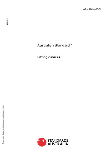
FEMA NATIONAL US&R RESPONSE SYSTEMSTRUCTURAL COLLAPSE TECHNICIAN02-00MODULE 4 - LIFTING AND RIGGINGINCLINED PLANES (continued)APPLICATION OFINCLINED PLANESn Percentage of load based on slope and grade When an object comes to rest on a slope, the rescuermust determine the percentage of the loads weight thatneeds to be managed during the stabilization process.To estimate the load percentage first determine theamount of resistance the load surface has in relation tothe object.Discounting friction refer to the table below forapproximate weight based on slope.Slope/Grade45 degrees35 degrees25 degrees15 degrees Ramps Wooden Wedges Screw ThreadINCLINED PLANESTravel length divided by height MA13/5 2.6% of Load’s Weight100%60 %40%25% 2.6:1 MA5 feet13 feet12 feetPERCENTAGE OF LOADBased on slope & gradeLEVERSResistanceTo ForceFriction “Give me a lever long enough and a prop strong enough,I can single handed move the world.”Archimedesn Application of levers: Move a load that is heavier than can be moved bymanpower alone. Pulling/hauling. Raising. 45 degrees100% 35 degrees 25 degrees60%40% 15 degrees25%THE APPLICATION OFLEVERS Move, haul, or pull a load that wouldnormally be outside of the human’spower window.500/5 100 5:1 MAForcen Leverage is the means of accomplishing work with levers: Transfers force from one place to another. Changes the force's direction.5 feet1 foot500 LB.LoadFulcrumCLASSES OF LEVERSCLASS ONE LEVERn Class One Lever Fulcrum is placed between theforce applied and the load.Fulcrum is placed between the force applied and weight(load).MA: Used when a decided advantage is desired.ForceLoadFulcrum Examples: Crowbars, wrecking bars, pliers, scissorsSM 48Used when a decidedadvantage is required
FEMA NATIONAL US&R RESPONSE SYSTEMSTRUCTURAL COLLAPSE TECHNICIAN02-00MODULE 4 - LIFTING AND RIGGINGCLASSES OF LEVERS (continued)CLASS TWO LEVERLoad is placed between theforce and the fulcrum.n Class Two Lever: Weight (load) is placed between the force and thefulcrum.MA: Used for advantage in moving heavy materials on ahorizontal/near horizontal surface.Used for advantage inmoving materials on ahorizontal or nearhorizontal surface.LoadForceFulcrumExamples: Wheelbarrows, furniture dolliesn Class Three Lever: Force placed between the fulcrum and the load. MA: used when force may be sacrificed for distance. Examples: Brooms, shovels, baseball bat, tweezersSCREW-TYPE MACHINESCLASS THREE LEVERForce is placed between thefulcrum and the load.LoadUsed when force may besacrificed for distance.ForceFulcrumn Examples of screw-type machines: Worm gears, screwjacks and valves in fire hydrants.n Characteristics of these machines are: Combination of a lever and an inclined plane.Thread of a screw is an inclined plan encircling the stemof the screw.Handle is the lever.Thread works in a corresponding groove in the base.Thread is forced to move under the load.One rotation of the handle moves the thread through adistance equal to the distance between it and the threadbelow it.Distance moved is call the pitch of the screw.PULLEYSTWO CONFIGURATIONSOF PULLEYSn Application related to loads: Fixed pulleys called COD’s that provide no mechanical advantage.LiftingPullingMovingChange directionMechanical advantageReduce friction(only Change Of Direction) Moving pulleys that are rigged to theload and move when load is pulled,hauled, or raised.SM 49
FEMA NATIONAL US&R RESPONSE SYSTEMSTRUCTURAL COLLAPSE TECHNICIAN02-00MODULE 4 - LIFTING AND RIGGINGPULLEYS (continued)n Change direction of effort: FIXED PULLEYSPulley is stationary: Does not change theoreticalmechanical advantageAnchor COD Pulleyn Gain mechanical advantage:ForceLoad Pulley is moving: Changes mechanical advantagedepending on useBitter end at the load — the simple system is oddBitter end at the anchor — the simple system is evenThe difference between theoretical and actual mechanicaladvantage is "friction"TRAVELING PULLEYSTraveling PulleyAnchorForce2:1n What class of lever is a pulley?LoadADVANCED LEVERAGE APPLICATIONS A-Frame Gantryn The A-Frame Gantry is a fairly complex application ofleverage that involves floating an object in air between twohorizontal points.n The application for the gantry is most practical duringcollapse situations involving the movement of objects wherethere are no suitable overhead anchor points and craneaccess is not practical.n The A- frame may be made from two 6x6x14’-0” timbers thatare lashed together at the top, or by using a pair of 12 ftlong, aluminum rescue struts connected using special apexand foot connections. PULLEYSWhat class of lever?ForceFulcrumLoadTHE “A” FRAME GANTRYThe two lower ends of the A-frame must be connectedtogether, just above the ground, using a stout rope,webbing or chain.HThe legs should be spaced from 10 to 12 feet apart atthe ground.Tie 6x6 at basen A 15:1 or 20:1 compounded mechanical advantage pulleysystem used for swinging the A-frame is attached to theapex of the gantry and anchored to an appropriatebombproof anchors.SM 410
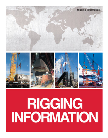
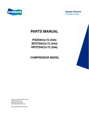
FEMA NATIONAL US&R RESPONSE SYSTEMSTRUCTURAL COLLAPSE TECHNICIAN02-00MODULE 4 - LIFTING AND RIGGINGA- FRAME GANTRY (continued)n The object (Load) is attached to the apex of the Gantryusing a short rigging strap, and a lowering control rope isconnected opposite the mechanical advantage pulleysystem.n As the gantry is tensioned and elevated, the load starts torise. A hoist or come-along may also be used to initiallysuspend the load.n The A-frame apex must be rotated to be centered over theload, but the angle between the ground and the A-frameshould not be less than 45 degrees.A - Frame Gantry Forcesfor 45 deg. initial angle900 lb in each leg1250 lb in Rope At this angle the initial force on the hawling rope systemis about 25% greater than the load, assuming that thehauling anchors are placed at least 30 ft from theAframe feet. The force in each of the A-frame legs will be about equalto the load as the lifting begins. As lifting begins, forces are generated in the A-Framelegs- The horizontal force tending to move the base of eachof the A frame legs away from the load will be about2/3 of the load.-- There will also be a verticle load acting into theground at the frame base that is about equal to thishorizontal force.These forces need to be resisted by the ground,and/or some type of restraint system.The dimensions and forces for two A-Frame systems,using 45 and 60 degree initial angles are shown in theadjacent slides and on the following page.SM 411630 lb1000 lb630 lb457.5 ft630 lb30 ft630 lbA - Frame Gantry Forcesfor 60 deg. initial angle900 lb in each Leg900 lb in Rope430 lb1000 lb630 lb606 ft430 lb630 lb30 ft
FEMA NATIONAL US&R RESPONSE SYSTEMSTRUCTURAL COLLAPSE TECHNICIAN02-00MODULE 4 - LIFTING AND RIGGINGDIAGRAM OF TIMBER A-FRAMETHE “A” FRAME GANTRYHTie 6x6 at baseDIAGRAM OF A-FRAME FORCES at 45 degree angle(per 1000lb load. Suggested maximum Load 4000lb)Loads for 60 degree shown in slide adjacent slideA - Frame Gantry Forcesfor 45 deg. initial angle1000 lb in each legA - Frame Gantry Forcesfor 60 deg. initial angle1250 lb in Rope900 lb in each Leg900 lb in Rope630 lb1000 lb430 lb1000 lb630 lb45630 lb606 ft430 lb630 lb7.5 ft630 lb30 ft630 lbSM 41230 ft
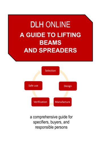
FEMA NATIONAL US&R RESPONSE SYSTEMSTRUCTURAL COLLAPSE TECHNICIAN02-00MODULE 4 - LIFTING AND RIGGINGA-FRAME GANTRY (continued)n In most cases it is necessary to provide a footing/baseplatefor each leg of the A-frame. In very firm ground, a shallow hole may provide enoughresistance to the compression forces that are exertedwhen the A -frame legs rotate.- The forces at the edges of the 6x6 will dig into theground and create their own bearing surfaces. In softer ground, it may be necessary to use a pair of 12”square plywood gussets to spread the load, andneoprene pads will be helpful in providing shapedbearings for the edges of the 6x6 as it rotates. On concrete paving surfaces, it will be necessary tocarefully restrain the 6x6 from slipping, and provide forthe rotating bearing. In the Airshore Rescue Strut A-Frame system, a 12”square baseplate that provides for the bearing androtating leg.- This baseplate must be properly restrained usingrope, chain, or other mechanical anchors.THE “A” FRAME GANTRYPair of 6x6x14ft lashed at 12ft, A is set at 60 degreesTHE “A” FRAME GANTRY2-Airshore “F” Struts w/steel fittings, just past verticaln As the gantry is arched over, the load elevates until thegantry is straight up and the object being lifted is directlybeneath apex. As the load moves past 90 degrees, the pulley systembecomes useless, and the lowering ropes take over thecontrolled lowering of the load.HIGH PRESSURE AIR BAGSn Characteristics are: Neoprene/butyl rubber — outerSteel/Kevlar — reinforcementVariety of sizesOuter layer textured to reduce slippageCapacity is calculated at 1" of liftAt maximum height, usable capacity typically is reducedto 50% of the rated capacity.SM 413HIGH PRESSURE AIRBAGS Characteristics– Neoprene/butyl rubber– Steel kevlar reinforced– Variety of sizes– Maximum capacity is calculated at 1inch of lift– Very low capacity at max height
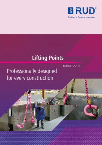
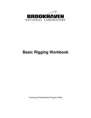
FEMA NATIONAL US&R RESPONSE SYSTEMSTRUCTURAL COLLAPSE TECHNICIAN02-00MODULE 4 - LIFTING AND RIGGINGHIGH PRESSURE AIR BAGS (continued)HIGH PRESSURE AIRBAGSn Application: Maximum stack of two high (bag centers must align)Lift capacity is that of the smaller bagLift height is increasedEnsure that the smallest bag has capacity for the liftPlace the large bag on the bottomKeep air pressure in the larger bag less than in thesmaller bagLOADIncreased surface area increased lifting capacityCOLUMN OF AIRBASE OF SUPPORTHIGH PRESSURE AIR BAGSn Bags in tandem: AIR BAGINFLATEDLOADBags side-by-side or at two points on a loadMaximum working capacities added togetherConsider lift height as well as load weightCOLUMNn Working area:OREDUCEDSURFACEAREACONTACTFAIRBASE OF SUPPORT Flat surfaceSolid cribbing bed under bagEstablish safe zonesPressurize bags slowly and watch for load shiftIf load is uncontrolled, stop the lift and reevaluateUse solid cribbing or wedges under the load to stabilizeSee manufacturer's manual for additional informationn Calculating lifting capabilities: HIGH PRESSURE AIR BAGSMaximum working pressure of individual bagSurface area contact (is smaller than bag dimensions)Working pressure of bag under load when in useMaximum working capacity is the maximum contactsurface area of the bag (always smaller than bagdimensions) times the maximum working pressure.As the air bag lifts and "pillows," surface contact isreduced and the lift capacity is decreasedEXAMPLEn 10" x 10" air bag is 100 sq.in. in total area. The maximumworking pressure is 118 PSI, and 100 sq.in. times 118 PSI 11,800 lbs. of lift (5.9 tons) if full bag area was in surfacecontact. From chart, actual capacity is 4.8 tons.Dimension6”x 6”6”x 12”10”x 10”15”x 15”15”x 21”20”x 20”24”x 24”28”x 28”36”x 36”Capacity1.5 Tons3.24.812.017.021.831.843.873.4Lift Ht. Weight3”2 lbs3.53548109131116132216302048HIGH PRESSURE AIR BAGSI.D. Tag is right on BagMAXIFORCEAIR LIFTING BAG SERIAL#KPI 12940492MAXIMUM LIFTING CAPACITY 12TONS 10845 KGMAXIMUM WORKING PRESSURE 118 PSI 8 BARSMAXIMUM LIFTING HEIGHT 8 IN. 208 MMMAXIMUM AIR CAPACITY 2.3 CU FT 65 LITERSPARATECK INCORPORATED FRANKFORT, IL. U.S.A.READ INSTRUCTIONS BEFORE OPERATING THIS EQUIPMENTn Check bag for Identification Tag that lists maximumpressure, load and lift height data.SM 414
FEMA NATIONAL US&R RESPONSE SYSTEMSTRUCTURAL COLLAPSE TECHNICIAN02-00MODULE 4 - LIFTING AND RIGGINGMECHANICS OF LOAD STABILIZATION AND MOVEMENTn Four functions that need to be addresses before any load isstabilized, lifted, or moved: Center of gravityLoad Stability including Shims, Wedges & CribbingEstimating Load WeightLifting Functions including Critical Angle ConsiderationsLIFTING OR MOVING ALOADFUNCTIONS TO BE ADDRESSED Center of gravity Load stability– wedges & cribbing Estimating Load weight Lifting Functions– critical angleCENTER OF GRAVITYn Center of gravity is where any load's entire weight isconcentrated.n Loads will seek to have their center of gravity below thepoint of support.n Moment of force (distance times weight) is created when thecenter of gravity moves around a fulcrum.n Narrow base of support can rapidly become fulcrum (pivotpoint) for the load.n The higher the center of gravity is located in the load, thewider and more stable the base of support needed tomaintain the static equilibrium.n A load with a relatively high estimated center of gravity andnarrow base of support must be considered to be in a stateof unstable equilibrium moment of force of load's ownweight (or external force) can cause the load to move into astate of equilibrium (i.e., fall over).n Load rotation when the lifting point of the rigging is notdirectly above the center of gravity.SM 415CENTER OF GRAVITYAND LOAD STABILITYUNSTABLESTABLECGCGConnection point belowCG makes objectunstable.
FEMA NATIONAL US&R RESPONSE SYSTEMSTRUCTURAL COLLAPSE TECHNICIAN02-00MODULE 4 - LIFTING AND RIGGINGLOAD STABILIZATIONn Make load attachments above center of gravity whenpossible.n Place attachments above and on either side of the estimatedposition of center of gravity to control load. Wind or shaking from an earthquake (external force) canmove a load with high estimated center of gravity andnarrow base of support.n Widen and extend the load base of support when: Distance from base of support to estimated center ofgravity is greater than the width of base of the support.Loads showing any signs of rocking or swaying unstable equilibrium state. Consider that center of gravitymay change: Ground shaking changing position of internal load such asmachinery in structure Base of support shiftingSHIMS (WEDGES)SHIMS / WEDGES / CRIBBINGn Characteristics Douglas Fir or Southern PineTends to crush slowlyProvides advance warning of failure500 pounds per sq. inch (psi) maximum load capacityUse of shims to changedirection“MARRYING” WEDGESn Shims (wedge): Stabilizing tools.Incline plane (MA).Take up void space.RIGHTn Wedge Set: Snug up or tighten load.Change of direction.SM 416WRONG
FEMA NATIONAL US&R RESPONSE SYSTEMSTRUCTURAL COLLAPSE TECHNICIAN02-00MODULE 4 - LIFTING AND RIGGINGn Cribbing Types: CRIBBINGBox (2 x 2 Crib) : four points of contactCrosstie (3 x 3 Crib) : 9 points of contactSolid : entire surface area contact6000 lbs. per contact pointn Cribbing strength is determined by figuring the surface areaat each point of contact and multiplying by the wood strength 500 psi for Douglas Fir, but as low as 250 psi for softerwood.n Example: 4x4 box cribbing is really 3.5" X 3.5" 12.25 X 500psi. 6,125 lbs. per contact point. Call it 6000 lbs- Total for Box Crib 4 x 6000 24,000- Total for 3 x 3 Crib 9 x 6000 54000Four point systemNine point systemCRIB STABILITYCENTER1/3OFCRIBLOADMUSTBE6x6 box cribbing is really 5.5" X 5.5" 30.25 X 500 lbs. 15,125 lbs. per contact point. Call it 15,000 lbs- Total for Box Crib 60,000 lbs- Total for Crib 3 x 3 135,000 lbsn Height of cribbing when used to stabilize loads to be movedshould be limited to two times the width. Support the load on the contact points (load to ground). When using cribbing to support collapsed structures theheight may be increased to three times the width.CALCULATING THE WEIGHTSOF COMMON MATERIALSLENGTH x WIDTH x HEIGHT CUBIC FT Steel490 lbs. per cubic foot ( pcf) Concrete 150 lbs. per cubic footn See Module 2a for additional information regarding Cribbingincluding: Overlap at cor
road that had a bridge with a 10,000 load limit. The officer responded to the question by saying that "it was an emergency". Rescue personnel often think that the physical laws of the universe do not apply when there is "an emergency". Gravity is one of the laws of the un