Transcription
AS-interface Tutorial AS-interface Simple,Robust,Device-Level,Bus
AS-interface Tutorial, Rev 1.0NOTES:2InterlinkBT 3000 Campus Drive Plymouth MN 55441 www.interlinkbt.comPhone: (01) (763) 694-2300 Fax: (01) (763) 694-2399 Toll Free: (888) 546-5880
AS-interface Tutorial, Rev 1.0AS-interface TutorialRevision 1.0Table of ContentsTOPIC1.PAGEAS-interface1.1. v2.0 and v2.11.2. v2.04441.3. v2.1Version 2.1 Highlights2.1. Overview of v2.15553.2.2. Up to 62 nodes2.3. AnalogAS-interface in the Modern Industrial Enterprise5554.3.1. AS-interface for OEMs3.2. AS-interface for Batch and Continuous Flow ProcessingAS-interface Analog Response Times6674.1. Response Time85.Mixing Legacy v2.0 and v2.1 Nodes96.AS-interface Layout, Power Budget, and Physical Media6.1. Layout6.2. Repeaters1010116.3. Physical Media6.4. Power and Grounding6.5. Auxiliary Power1111146.6. Power BudgetTroubleshooting AS-interface7.1. Open media1517177.2. Shorted data lines7.3. Shorted power lines7.4. Shorted transceiver or transceiver power regulator1717187.5. Open transceiver or transceiver power regulator7.6. Other transceiver malfunctionsSummary1818182.7.8.InterlinkBT 3000 Campus Drive Plymouth MN 55441 www.interlinkbt.comPhone: (01) (763) 694-2300 Fax: (01) (763) 694-2399 Toll Free: (888) 546-58803
AS-interface Tutorial, Rev 1.01.AS-interface AS-i is an acronym for Actuator Sensor Interface. This may be the most high-tech bus ofthe traditional industrial networks. A huge amount of work has gone into its design tomake it the simplest bus to use.The signal is robust, balanced and has parity redundancy, so cabling is simple. One signalsegment can be laid out anyway; star, tree or bus, without drop limitations. The onlyrequirement is that all the cabling in a signal segment must be equal to 100 meters or lessin total length. In addition there are no terminating resistors.The traditional AS-i flat cable is still being used for many applications, but today manyusers and OEMs are switching to round cable with M12 connectors. The M12 connector isan international specification defined by the EN50 044 Standard. The M12 is also knownby names such as euro or micro and is extremely rugged. Some manufacturers haveachieved over 40 pounds (18-kg) pullout ratings. It is truly a heavy-duty IP67 connectionwith the copper wires of the cable being soldered or crimped to gold-plated brass pins andsleeves at the factory.1.1.v2.0 and v2.1Bus typeBus topologyPhysical distance on a single signalsegmentPhysical distance with 2 repeatersand master in the centerTransmission signalSpeedBus powerAttendance check per scanError detectionError correctionAddress setting1.2.Master-to-slave, single masterFree form, unrestricted branching100 meters500 metersAlternate Pulse Modulation with Manchester II bitencoding impressed upon 24VDC bus power carrier167.5 kbps, 5 msec to read/write 31 v2.0 discretenodes, 10 msec to read/write 62 v2.1 discrete nodes2 amps using the same 2 wires as the data signalYes, an attendance list is programmed in the masterand checked each scan.Yes, single parity bit check and bit repetition.Yes, master will poll the node again if it doesn’tunderstand. If the node doesn’t understand the masterit won’t respond, then the master will poll the nodeagain after a time-out.Off line via a hand held programmer or online via themaster. Some masters are capable of automaticallyaddressing swap-out nodes during replacement.v2.0Total number of nodes31 slaves and 1 masterInput/Output bits4/4Analog capabilityYes, but not standardizedTotal discrete input/output points per network124 In/124 Out4InterlinkBT 3000 Campus Drive Plymouth MN 55441 www.interlinkbt.comPhone: (01) (763) 694-2300 Fax: (01) (763) 694-2399 Toll Free: (888) 546-5880
AS-interface Tutorial, Rev 1.01.3.v2.1Total number of nodes62 slaves and 1 masterInput/Output bits4/3Analog capabilityYes, definedTotal discrete input/output points per network248 In/186 OutMaximum number of analog points per network1242. AS-interface v2.1 Highlights2.1.Version 2.1Version 2.1 makes the worlds most popular actuator-sensor bus more powerful. Morediagnostics, better analog capability and up to 62 field nodes per drop are availablewithout the complexity of the higher-level buses. AS-interface is a simple master-to-slavestructure. The master controls all time and network traffic. Protocol is embedded in thehardware. There are no configuration files to maintain.2.2.Up to 62 nodesIn v2.0 all nodes are “Single Address Slaves”. Version 2.1 specifies “Single AddressSlaves” and “A/B Address Slaves”. Single address slaves have a maximum of 4 discreteinput bits and 4 discrete output bits. The address range is 1-31, with 0 being reserved fornew incoming slaves. “0” is the default address set by manufacturers when a slave leavesthe factory. The “A/B-Slaves” are one of the major changes of v2.1. The address rangesare 1A-31A and 1B-31B. A maximum of 4 discrete input bits and 3 discrete output bits areavailable per “A” or “B” nodes. The new AS-i masters from Bihl Wiedemann can be usedwith legacy v2.0 single address slaves, v2.1 single address slaves and v2.1 A/B slaves.2.3.AnalogVersion 2.0 allowed analog I/O, but it was not completely defined. Version 2.1 definesanalog data. The master polls the analog station multiple times and assembles thefragmented analog data into complete 16 bit values for delivery to PLCs, Industrial PCs orhost buses. Due to AS-i’s low overhead analog values are updated as quick as mostapplications need.3. AS-interface in the Modern Industrial EnterpriseThe two network level structure is becoming the model for many manufacturers that aretrying to tie their ERP systems to the factory or process floor. This is replacing the threelevel structure that had an “Information Level”, a “Controller Level” and a “Device Level”.The Information and Controller Levels are being collapsed into one. In most applicationsthe Device Level is not changing. Tying the ERP system to production is the motivebehind the change. A truer and more real-time view of production is possible if the ERPsystem can get down to the controllers that carry out production. In many industries todayInterlinkBT 3000 Campus Drive Plymouth MN 55441 www.interlinkbt.comPhone: (01) (763) 694-2300 Fax: (01) (763) 694-2399 Toll Free: (888) 546-58805
AS-interface Tutorial, Rev 1.0content data logging, as well as other recorded quality tests, must be documented andarchived for years to guard against frivolous litigation.There are many technologies behind the two network levels. The most crucial are themodern Layer 3 Ethernet Switches and the venerable RFC2323 better know as IP(Internet Protocol). Layer 3 switches combine the features of a router and a Layer 2managed switch. This allows the building of networks with defined subnets.[Refer to Appendix A]Therefore, within an enterprise several subnets can exist being defined by somefunctionality, such as sales, purchasing, etc. and various sub-divisions withinmanufacturing. IP is the addressing mechanism to get around the subnets.AS-interface is at the device level along with many other buses such as DeviceNet,ControlNet, Profibus (DP, PA, FMS), FOUNDATION Fieldbus, Interbus, CANOpen, CC-Link,Modbus and Modbus Plus.3.1.AS-interface for OEMsAs one OEM claims, “I make the same machines over and over again, but differently eachtime.” What he is saying is that each one of his customers has some slight variation.The enterprise view [Appendix A] shows the versatility of AS-interface. It is supported bymore PLC manufacturers than any other bus. It can be a sub bus off almost any otherbus. It can be a drop off Industrial PCs and there are Ethernet to AS-interface gateways.In one way or another AS-interface can be integrated into almost all enterprises. OEMscan create a baseline machine using AS-interface. Version 2.1 provides the power mostOEMs need. The gateway or host is all that changes from customer to customer. Thebenefits are exceedingly significant. The physical machine and the device level controlsystem can be fine-tuned with standard, semi-standard and customized media and I/O.Semi-standard and customized products are where the biggest cost savings anddifferentiation are achieved from one OEM to another.3.2.AS-interface for Batch and Continuous Flow ProcessingThe versatility of AS-interface shown in the enterprise view along with the simplicity of itsembedded protocol are reasons that AS-interface is popular with manufacturers of I/Odevices for batch and continuous flow processing. Most manufacturers of PLCs and DCSsused in processing have AS-interface card modules that go into their back plane.Many manufacturers have embedded AS-interface in their discrete products. More analogv2.1 AS-interface products will come in the future. Some popular AS-interface embeddedproducts are:6 Quarter-turn valves (pneumatic and electrical actuation) Quarter-turn valve indicatorsInterlinkBT 3000 Campus Drive Plymouth MN 55441 www.interlinkbt.comPhone: (01) (763) 694-2300 Fax: (01) (763) 694-2399 Toll Free: (888) 546-5880
AS-interface Tutorial, Rev 1.0 Indicating lights and light towers Sensors (inductive, capacitive, and photoelectric) Motor control (combination contactor coil and overload device)The ATO (AS-interface Trade Organization) website, www.as-interface.com, has a verygood product-manufacturer search engine. The search categories as of this writing are:AccessoriesLoad FeedersAddressing and Diagnostics UnitsMastersAnalog ModulesOther ActuatorsCablesOther SensorsCapacitive SensorsOutput ModulesChipsPhotoelectric SensorsCommand, Signaling and Monitoring UnitsPneumatic ActuatorsCoupling Modules / Mounting PlatesPneumatic ModulesEarth Fault Monitoring SystemsPower Supply UnitsElectric ActuatorsRepeatersExtendersSafety at Work ProductsGatewaysServicesHydraulic ActuatorsSoftwareInductive SensorsSpecial ProductsInput / Output ModulesUltrasonic SensorsInput ModulesValve Position IndicatorsWhat stands out about AS-interface is the number of products that have AS-i embeddedinto the input or output device.4. AS-interface Analog Response TimesThe original AS-interface consortium was composed of mostly discrete I/O manufacturers.Among them were IFM, TURCK, P&F and FESTO. Analog was not a major priority anddiscrete favored decisions were made. With v2.1 analog capabilities are very real, but theread-write response time of analog is not as hot as discrete only AS-interface nodes.To illustrate, we will look at a real application: A user installed a v2.0 network about 3years ago, which is working fine. The network has 24 discrete nodes and is running fasterthan the PLC. Two more discrete nodes need to be added, the same as the other 24nodes, plus 4 channels of analog in and 2 out. The user found the analog I/O nodes hewants - one 4 channel in and another 2 channel out. The questions are: What will be theresponse time for the discrete and the analog? Does the master need to be changed? Isthere a better solution?InterlinkBT 3000 Campus Drive Plymouth MN 55441 www.interlinkbt.comPhone: (01) (763) 694-2300 Fax: (01) (763) 694-2399 Toll Free: (888) 546-58807
AS-interface Tutorial, Rev 1.04.1.Response timeThe discrete response time is pretty easy. A network of 31 nodes and 1 master can do acomplete read-write in 5 msec. The actual time per discrete node to use is 0.165 msec.The proposed network of 28 nodes will be 4.62 msec, but only for the discrete I/O. The 4channel analog node will actually take a little less than 130 msec.The analog value is actually sent to the master in fragments requiring 7 scans per analogchannel. Since there are 4 analog channels the node will require 28 scans at 4.62 msecfor a complete read. That is, 28 x 4.62 msec 139.36 msec.The 2-channel analog out will be exactly half of that, or 64.68 msec. In reality the analogout will be updated twice as often as the analog in.In many applications 140 msec is fast. Compared to process buses and older serialcommunications based on RS-232C or D and proprietary RS-485 that measured level ortemperature, this speed is indeed sufficient. However, it is not fast enough for web controlor some of the other motion applications.One way to improve the speed, although it still may not be fast enough for motion control,is to break the 4 analog channels in into 2 nodes of 2 channels. This will add another nodefor a total of 29, but will improve the analog speed. Following are the calculations:29 nodes x 0.165 msec 4.78 msec/scan (read-write response time for all discrete)7 scans/analog channel x 2 analog channels/node x 4.78 msec/scan 70.0 msecresponse time per node (rounded per scientific notation).Since the channels are updated sequentially, rather than concurrently, this is also theresponse time per analog channel.8InterlinkBT 3000 Campus Drive Plymouth MN 55441 www.interlinkbt.comPhone: (01) (763) 694-2300 Fax: (01) (763) 694-2399 Toll Free: (888) 546-5880
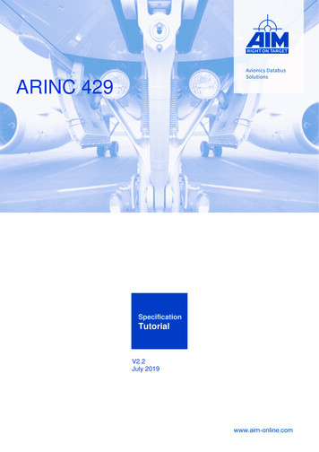
AS-interface Tutorial, Rev 1.05. Mixing Legacy v2.0 and v2.1 A 24A 25A 26A27A 28A 29A30A31A16B17B18B19B 20B 21B22B23B 24B 25B 26B27B 28B 29B30B31BFigure 1AS-interface does not require any correlation between the physical location and the logicaladdress, but for this example we will create a linear bus topology with consecutiveaddressing.There are five types of AS-interface nodes from an addressing standpoint:Version 2.0 and 2.1 address 0 for incoming nodesVersion 2.0 single slaves address range 1-31 (shown in Figure 1 as addresses 1-7)Version 2.1 single slaves address range 1-31 (shown in Figure 1 as addresses 8-15)Version 2.1 A slaves address range 1A-31A (shown in Figure 1 as addresses 16A-31A)Version 2.1 B slaves address range 1B-31B (shown in Figure 1 as addresses 16B-31B)Single slaves, either v2.0 or v2.1, and A/B slaves can be mixed as long as the master isv2.1 compliant.The v2.1 A/B slav
AS-interface Tutorial, Rev 1.0 InterlinkBT 3000 Campus Drive Plymouth MN 55441 www.interlinkbt.com Phone: (01) (763) 694-2300 Fax: (01) (763) 694-2399 Toll Free: (888) 546-5880 6 content data logging, as well as other recorded quality tests, must be documented and archived for years to guard against frivolous litigation.


![Database Management System [DBMS] Tutorial](/img/2/dbms-tutorial.jpg)