Transcription
Temperature conditions during 'cold' sheet metal stampingCitation of the final article:Pereira, Michael P and Rolfe, Bernard F 2014, Temperature conditions during 'cold' sheetmetal stamping, Journal of Materials Processing Technology, vol. 214, no. 8, pp. 1749-1758.This is the accepted manuscript. 2014, ElsevierThis peer reviewed accepted manuscript is made available under a Creative CommonsAttribution Non-Commercial No-Derivatives 4.0 Licence.The final version of this article, as published in volume 214 of Journal of Materials ProcessingTechnology, is available online 14.03.020Downloaded from Deakin Research Online,Deakin University’s Research RepositoryDeakin University CRICOS Provider Code: 00113B
Temperature conditions during ‘cold’ sheet metalstampingMichael P. Pereira a, Bernard F. Rolfe baInstitute for Frontier Materials, Deakin University, Geelong, VIC 3217, AustraliaCorresponding author, E-mail: m.pereira@research.deakin.edu.au,Tel: 613 5227 3353, Fax: 613 5227 1103bSchool of Engineering, Deakin University, Geelong, VIC 3217, AustraliaE-mail: bernard.rolfe@deakin.edu.auAbstractThis paper investigates the friction and deformation-induced heating that occurs during the stamping of highstrength sheet steels, under room temperature conditions. A thermo-mechanical finite element model of a typicalplane strain stamping process was developed to understand the temperature conditions experienced within thedie and blank material; and this was validated against experimental measurements. A high level of correlationwas achieved between the finite element model and experimental data for a range of operating conditions andparameters. The model showed that the heat generated during realistic production conditions can result in hightemperatures of up to 108 C and 181 C in the blank and die materials, respectively, for what was traditionallyexpected to be 'cold' forming conditions. It was identified that frictional heating was primarily responsible forthe peak temperatures at the die surface, whilst the peak blank temperatures were caused by a combination offrictional and deformation induced heating. The results provide new insights into the local conditions within theblank and die, and are of direct relevance to sheet formability and tool wear performance during industrialstamping processes.Keywords: Advanced high strength steels; Metal forming; Temperature; Thermo-mechanical finite elementmodel; Tool wear
1. IntroductionThe increased use of advanced high strength steels (AHSS) in the automotive industry hasresulted in an increase in formability and wear issues during stamping production. Tosuccessfully stamp AHSS, experience from the stamping press shop shows that press speedsand production rates often need to be reduced to minimize work-piece splitting and/or toolwear problems. This indicates that friction and deformation-induced heating are ofsignificance to the stamping of higher strength sheet steels, for what is expected to be ‘cold’forming conditions.The phenomena of deformation-induced heating and frictional heating are well known andhave been discussed in the literature for many years. For example, the early work by Farrenand Taylor (1925) showed that approximately 90% of the work done is converted to heatduring the rapid plastic deformation of several metals. Archard (1959) described thetheoretical maximum flash temperatures that occur at the surfaces of rubbing materials, wherenearly all the energy dissipated by friction appears as heat. The effect of this deformationinduced and frictional heating on the lubrication and wear performance for sheet metal ironingprocesses has been studied recently, with temperatures in the order of 100 C observed nearthe tool surface for the ironing of stainless steel sheet (Nielsen et al., 2011). However, theanalysis of friction and deformation-induced heating during room temperature sheet metalstamping has received little attention in the literature. Due to the increased work and contactpressures required to form the higher strength sheet materials (Pereira et al., 2008), significanttemperatures can be generated at the blank and tool surfaces during stamping processes.Recently, there have been a few studies that have used finite element analysis (FEA) toexamine the temperatures generated in the blank and/or die during continuous bending-undertension-type processes. Groche et al. (2008) predicted that small temperature rises (less than20 C) can occur at the die radius region during the strip drawing of aluminum at 100 mm/s.For a draw-bending process, Kim et al. (2011) predicted that temperatures of up to 100 C canoccur in dual-phase (DP) steel blank material during industrial-type deformation rates(approximately 50 mm/s). Groche et al. (2008) showed that the peak temperature regionscorresponded to regions of galling on the tool surface, while Kim et al. (2011) concluded thatthe deformation heating has a significant influence on the failure behavior of the sheetmaterial.
The effects of friction and deformation-induced heating during discontinuous stamping-typeprocesses have received less attention in the literature. Considering an axisymmetric cupforming process, Kim et al. (2009) used finite element modeling to predicted that a dual phasesteel (DP590) blank and D2 tool steel die could reach maximum temperatures of 86 C and46 C, respectively. Pereira et al. (2010a) predicted that temperatures of over 100 C can occurat the die radius when stamping AHSS sheet grades (DP590 and DP780) using D2 steel tools.Interestingly, the results by Pereira et al. (2010a) showed that the peak temperature rise wouldoccur at the beginning of the die radius, with the largest temperature rise occurring at the die(not blank) surface. The results presented by Kim et al. (2009) showed the opposite behavior– i.e. the maximum temperature on the die was predicted to occur towards the end of theradius, while the maximum temperature rise on the blank was more than double that on thedie. It is evident that further work is required to understand the temperature behavior in boththe sheet and die material during sheet metal stamping. This is particularly important whenconsidering the high temperatures predicted to occur when forming high strength steels andthe high process speeds used in many automotive stamping press lines.The studies discussed in the preceding paragraphs do not provide quantitative comparison ofthe finite element model temperature predictions to experimental temperature measurements.Therefore, there is also a need to provide experimental validation for the temperaturespredicted, to provide confidence in the numerical models.This study examines the friction and deformation-induced heating of high strength sheet steelsduring sheet metal stamping. A novel semi-industrial stamping test facility was instrumentedto provide temperature measurements at the die radius region, both at the die-to-blankinterface and below the die surface. A thermo-mechanical finite element model of the semiindustrial channel forming process was developed. The model demonstrates good agreementwith experimental measurements of punch force, blank and die surface temperature and diebulk temperature during a low speed stamping operation for two blank material grades. Thedeveloped finite element model was then applied to replicate the true ram speed duringproduction-type operating conditions – i.e. when the rate of the mechanical press is 32 strokesper minute. Consequently, the results provide new insights into the temperatures that occurwithin the die and blank material during industrial cold sheet metal stamping conditions.Finally, the model was utilized to highlight some of the factors that strongly influence thetemperature rise in the blank and die during sheet metal stamping.
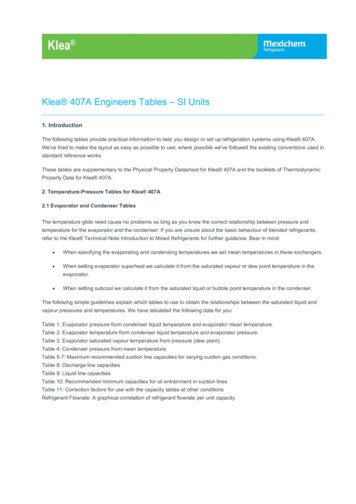
2. Experimental setup2.1. Process, geometry and operating conditionsFig. 1a shows the left side of the tooling of the semi-industrial stamping test, which forms thebasis of this study. A single-action mechanical press was used to stamp the channel-shapedcomponents, with the geometric and process parameters (detailed in Table 1) closelyrepresenting that of a typical automotive structural member. This section provides aspect ofthe experimental set-up relevant to this study. A full description of the experimental set-up isavailable in Pereira et al. (2013).Fig. 1: (a) Schematic of the tooling setup for the sheet metal stamping process. (b and c) Schematic ofthermocouple placement, showing section view of die corner inserts (not to scale).Table 1: Summary of the main geometric and process parameters used in the stamping tests.ParameterAverage blank holder forceAverage ejector pin forceBlank length, lBlank widthBlank thickness, tDie corner radius, rdDraw depthPress stroke lengthPunch corner radius, rpPress ratePunch width, aPunch-to-die gap, gValue27.21150261.8, 2.054020351, 32302.35UnitkNkNmmmmmmmmmmmmmmmin-1mmmmThe tooling setup permitted control of the blank holder force, via gas springs. The magnitudeof the blank holder force was chosen to be sufficient to maintain closure of the blank holder
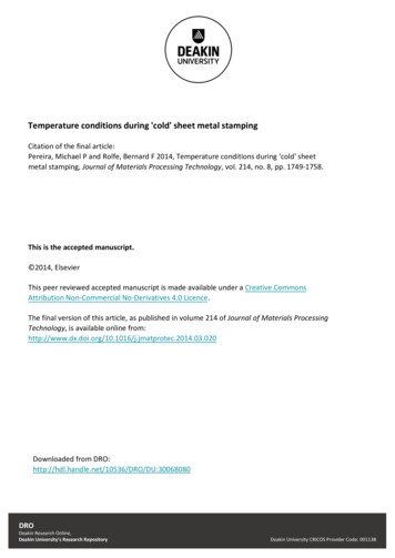
during the forming stroke, as determined from finite element model calculations. The punchforce was recorded during the stroke using a piezoelectric load cell that was located below thepunch. For all stamping tests, the blank material was lubricated with a thin film of anticorrosive oil, as delivered from the steel mill.The mechanical press operated continuously at 32 strokes per minute. At this press rate, thepunch speed is approximately 300 mm/s at the beginning of the forming operation andreduces to 0 mm/s at the end of the 40 mm forming stroke (see Fig. 2a), as governed by thegeometry and kinematics of the press and tooling system and the press crankshaft rotationalspeed. The mechanical press could also operate at a much slower speed of approximately 1stroke per minute (normally used for process setup, etc.). This press rate resulted in a punchspeed of approximately 8 mm/s and 0 mm/s at the beginning and end of the sheet metalforming operation, respectively (see Fig. 2b). For convenience, the two press operationmodes will be subsequently denoted as ‘high speed’ and ‘low speed’. As shown in Fig. 2, theduration of the forming stroke is approximately 0.25 and 8.9 seconds for the high and lowspeed modes, 302520151000.050.10.15Time [sec]0.2Punch speedPunch speed [mm/s]45001234 5 6Time [sec]78Punch displacementFig. 2: Punch speed and displacement during the forming stroke for the (a) high speed and (b) low speedstamping test settings.2.2. Temperature measurementsA J-type thermocouple, with an exposed junction and 0.2 mm diameter wire, was used tomeasure temperature during the stamping operation at the two locations shown in Fig. 1b and1c. In both cases, a 1 mm diameter hole was drilled from the rear of the die insert to allowPunch travel [mm](b)3303002702402101801501209060300Punch travel [mm]Punch speed [mm/s](a)
placement of the thermocouple, ensuring that the temperature measurement was close to themiddle of the blank-die contact region, where the approximately plane strain conditions exist.For the case shown in Fig. 1c, the thermocouple was located 2.2 mm below the tool surface,at the angular position of θ 40 along the die radius, thus providing bulk temperaturemeasurements close to the die radius surface. For the case shown in Fig. 1b, thethermocouple was positioned so that it protruded slightly from the die, at the location of θ 8 on the die surface. The compliance provided by the length of the thermocouple wire alongthe drilled hole ensured that the presence of the thermocouple did not alter the contactbetween the blank and die, but still ensured firm contact with the blank material as it movedover the die radius during the stamping process. Therefore, the ‘interface’ temperature at theblank and die surfaces was measured, because the thermocouple contacted both the blank anddie surfaces during the stamping operation.The thermocouple response time is in the order of tens of milliseconds, but the temperaturecould only be recorded at a maximum sampling rate of 1 Hz. Therefore, the temperaturemeasurements were performed during the low speed press mode, to allow the measurement ofthe temperature response during the 8.9 second forming stroke. The temperature response ofthe system during the low speed forming mode was examined in detail in order to establishthe likelihood of obtaining accurate temperature measurements for the given instrumentationsetup. For example, the finite element model showed that, at the point where the maximumtemperature rise occurs, the blank speed is less than 5 mm/s and that the blank surfacetemperature varies by less than 1 C at a distance of 1 mm either side of the measurementlocation. As such, it is believed that the combination of the rapid thermocouple responsetime, small size of the thermocouple, relatively slow movement of the blank and relativelylow temperature gradient in the die and blank materials, ensured that accurate temperaturemeasurements could be obtained during the low speed operating conditions. However, usingthis experimental setup, it is not possible to obtain accurate temperature measurements duringthe high speed test conditions.2.3. MaterialsTwo blank materials were examined in the experimental study – a 2.0 mm thick dual phasegrade steel (DP780) and a 1.8 mm thick high strength low alloy grade steel (HSLA400). Twoother material grades – DP590 and HSLA300 – were also examined in the numerical study.Table 2 shows the mechanical properties of the four blank material grades examined, asdetermined from quasi-static ambient temperature tensile tests. The tensile tests were
conducted in accordance with Australian Standard AS 1391-1991, at room temperature, in thedirection of forming (transverse to the sheet rolling direction), using a screw-driven testframe, with crosshead speed of 0.083 mm/s and 25 mm nominal gauge length for the tensilespecimens.Table 2: Mechanical properties of blank materials examined in this study.HSLA300HSLA400DP590DP780Yield strength [MPa]321447400587Tensile strength [MPa]485525659884Uniform elongation [%]19.216.816.28.33. Numerical setupThe channel forming process was analyzed using an implicit finite element code,Abaqus/Standard v6.10-1 (Dassault Systèmes Simulia Corp., 2010). A non-linear, transient,thermal-stress analysis was conducted. The problem was simplified to a one-half symmetric,two-dimensional, plane strain problem. The finite element mesh and numerical parametersrelating to the non-linear stress solution were based on the previous finite element models ofthe channel forming process developed by Pereira et al. (2008 and 2010a), and therefore willnot be repeated here.The important parameters relating to the thermal-stress solution are summarized in Table 3.The values of these parameters were carefully chosen to ensure all values were reasonable andwere within the range of values specified in relevant numerical studies presented in theliterature (Gåård et al., 2010; Kim et al., 2011; Pei et al., 2003). The parameters relevant tothe blank material and tools (die, holder, punch) are based on the properties of low carbonsteel and tool steel, respectively. Additionally, the plastic flow curves for the blank materialswere entered based on tabulated tensile test data for the four grades detailed in Section 2.3.The inelastic heat fraction, ηI, and friction energy heat dissipation fraction, ηF, relate to theamount of work from plastic deformation and friction that is converted into heat. The frictionheat factor, ξ, of 0.5 indicates that the frictional heat generated at the blank-tool interfaceduring sliding contact is distributed evenly into the two surfaces. The contact thermalconductance represents the heat transfer coefficient between the tools and blank – i.e. themetal-to-metal contact. It is known that this parameter is pressure dependent; however, forsimplicity, it was set as a constant value.
Given the time scale of the forming operation and relatively low temperatures involved in thestamping process, the effects of convection and radiation were assumed to be negligible, andwere not modeled. Furthermore, the strain rate and temperature dependence of all materialparameters were ignored for this analysis. This simplification is reasonable, considering thatthe die is modeled as a linear elastic solid and that the maximum temperature experienced inthe elastic-plastic blank is generally less than 100 C, apart from a few localized regions.Table 3: Important parameters relating to the thermal calculations for the thermo-mechanical finite elementmodel.Tools-3Blank-67.9 10-6Density [kg.mm ]7.7 10Expansion coefficient [ C-1]12 10-612 10-6460480Specific heat capacity [J.kg-1. C-1]-1-1-1Thermal conductivity [J.s .m . C ]Contact thermal conductance [J.s-1.m-2. C-1]225220 10-6Ambient temperature [ C]20Friction energy heat dissipation fraction, ηF0.9Friction heat distribution factor, ξ0.5Inelastic heat fraction, ηI0.9Friction coefficient, μ0.15The punch movement was specified via a displacement boundary condition using tabulatedamplitude data to accurately represent the experimental scenario (see Fig. 2). Due to the gassprings used for the blank holder and ejector pins, the magnitude of the blank holder force andejector pin force increases approximately linearly from the beginning of the forming stroke tothe end of the forming stroke by approximately 20%. This effect was included in the modelin the loading conditions, and is observed by the increasing punch force curves during theforming stroke in both the experimental and numerical cases (see Fig. 3).4. Results and discussionTo develop and validate the thermo-mechanical finite element solution, the low speedforming conditions were first replicated for both stamping conditions and blank materials andvalidated against the experimental measurements. Subsequent models, representing the highpunch speed test condition and different material and process parameters, were based on theinitial developed model. All experimental and numerical temperature results are based on asingle stamping operation, beginning from ambient operating conditions.
4.1. Low speed stamping conditions and model validationThe punch force curves predicted using the developed finite element models are compared tothe measured punch force curves in Fig. 3, for the DP780 and HSLA400 blank materialgrades during the low punch speed operational mode. Note that the corresponding values oftime at 10, 20, 30 and 40 mm of punch travel are shown on the secondary horizontal axeslabels in Fig. 3 for reference. For each material grade, five experimental curves are shown,highlighting the consistency of the experimental data. It is evident that the numericallypredicted punch force is in very good agreement with the experimental measurements for bothforming conditions.(a)01.27Time [s]2.73(b)4.588.9351.27Time [s]2.734.588.930Exp. 130Exp. 125Exp. 225Exp. 220Exp. 320Exp. 315Exp. 415Exp. 410Exp. 510Exp. 5FEA5Punch force [kN]Punch force [kN]350FEA50001020Punch travel [mm]3040010203040Punch travel [mm]Fig. 3: Experimentally measured and numerically predicted punch force during the low speed stamping operationfor (a) DP780 and (b) HSLA400 blank material.The experimental punch force curves show a small increase in magnitude near the end of thestroke (at approximately the last 3 mm of punch travel). Due the varying speed of the punchduring the stroke, the punch speed is less than 2.5 mm/s at this stage. This behavior is notevident during the high speed stamping mode and is therefore likely to be due to the increasedfriction between the blank and tools (and possibly stick-slip behavior) as a result of the lowsliding speeds between the blank and tools at the end of the forming stroke. The finiteelement models do not capture this behavior due to the constant coefficient of friction used.The measured and predicted temperature rise at the blank-die interface at θ 8 on the diesurface (see Fig. 1b) throughout the duration of the forming stroke is shown in Fig. 4.Similarly, the measured and predicted temperature rise at the location θ 40 at 2.2 mm belowthe die surface (see Fig. 1c) is shown in Fig. 5. For each condition, the temperature wascontinually recorded, showing the decay in temperature after the end of the forming stroke.
However, the finite element model predictions consider the forming stage only – i.e. from 0 to40 mm of punch travel, corresponding to the time period of 0 to 8.9 seconds. For this reason,the secondary horizontal axes labels in Fig. 4 show the corresponding values of punch travelat the process time of 0, 2, 4, 6 and 8 seconds for reference. The temperature rise aboveambient temperature is shown to permit easy comparison and thus allow the small differencesin the ambient temperature between the experimental measurements to be excluded.0(b)Punch travel [mm]15.2 27.2 35.5 39.630Exp. 125Exp. 220Exp. 315Exp. 410Exp. 55FEA(die)0FEA(blank)02468101214161820Temperature rise at die-blank interface [ C]Temperature rise at die-blank interface [ C](a)0Punch travel [mm]15.2 27.2 35.5 39.630Exp. 125Exp. 220Exp. 315Exp. 410Exp. 55002468Time [s]101214161820FEA(die)FEA(blank)Time [s]Fig. 4: Measured and predicted temperature rise during low speed stamping operation at the die-blank interface(at location θ 8 ) for (a) DP780 and (b) HSLA400 blank material.0(b)Punch travel [mm]15.2 27.2 35.5 39.61412Exp. 110Exp. 28Exp. 36Exp. 44Exp. 52FEATemperature rise below die surface [ C]Temperature rise below die surface [ C](a)0Punch travel [mm]15.2 27.2 35.5 39.61412Exp. 110Exp. 28Exp. 36Exp. 44Exp. 52FEA00024681012Time [s]1416182002468101214161820Time [s]Fig. 5: Measured and predicted temperature rise during low speed stamping operation at 2.2mm below the diesurface (at location θ 40 ) for (a) DP780 and (b) HSLA400 blank material.The experimental results in Figs. 4a and 4b show qualitatively similar behavior, with thetemperature rising rapidly and the peak temperature occurring at approximately 4 seconds. InFigs. 5a and 5b the rates of temperature rise and peak temperatures are lower, due to the timeand dissipation associated with the heat conduction from where it is generated at the die
surface to the position of the thermocouple below the die surface (see Fig. 1c). However,Figs. 4 and 5 show that the temperature rise at the interface for the DP780 material case isconsistently higher than that for the HSLA400 material. This is due to the increased frictionand deformation-induced heating caused by the higher strength and larger thickness of theDP780 sheet material.The finite element model predictions of temperature rise at the two locations shown in Figs. 4and 5, show good agreement with the temperature measurements for both blank materialconditions, with both the magnitude and the trend of the results correlating well. This highlevel of correlation between the FEA results and the experimental forming data, for the rangeof operating conditions, materials and parameters examined, provides a strong level ofconfidence in the model predictions. Furthermore, the correlation to the experimental data forthe two blank material conditions simulated was achieved with sensible/realistic thermal andfrictional FEA parameters shown in Table 3. This indicates that the developed model canaccurately simulate the mechanical response and the friction and deformation-induced heatingbehavior during the typical sheet metal stamping process examined and therefore can beapplied to other operating conditions.4.2. High speed stamping conditionsThe finite element model developed in the previous section was applied to analyze the frictionand deformation-induced heat generation in the blank for the high speed stamping conditions(i.e. replicating the true ram speed of the semi-industrial stamping operation running at 32strokes per minute – see Fig. 2a). This section discusses the results for the DP780 blankmaterial and operating conditions only, as the forming of AHSS is of primary interest.4.2.1. Maximum temperatureFrom a tool wear and sheet formability perspective, the maximum temperature experiencedby the die and blank is of primary concern. Fig. 6a shows the predicted maximumtemperature for the blank and die at any given instant during the stamping process, for boththe low and high speed forming conditions using the DP780 material. Fig. 6b shows themaximum temperature that occurs over the die radius region for the die and blank materials.In this figure, the maximum temperature on the blank surface is shown with respect to theposition of the blank when this maximum temperature occurred (relative to the die radius).Conversely, Fig. 6c shows the maximum temperature distribution over the blank surface withrespect to the final location on the formed blank surface. Consideration of the three graphs in
Fig. 6 together allows the reader to determine the magnitude, time and location at which themaximum temperature occurs during the stamping process on the die and blank (as indicatedby the circle and square markers, respectively). Therefore, Fig. 6 shows that the predictedmaximum temperature on the die during the high speed stamping is 181 C, occurring whenthe punch has travelled 23 mm and at a location of θ 6 on the die radius (0.5 mm from thebeginning of the die radius). Similarly, the maximum temperature on the blank is predicted tobe 108 C, occurring at 9.8 mm punch travel at a location of θ 62 (which corresponds to thefinal location on the sidewall of the formed part of 32 mm from the bottom of the channel, asshown).Angle on die radius [deg]04590(b)200200180180Maximum temperature [ C]Instantaneous maximum temperature[ 3040-2200180Maximum temperature [ C]246810 1214 1618 20Distance from beginning of die radius [mm]Punchstroketravel [mm][mm]Punch(c)0High speedon dieLow speedon dieHigh speedon blankLow speedon blank160140120100Vertical position on sidewallof formed channel [mm]80603240Angle on dieradius, θ [ ]20010203025040Vertical position on sidewall of formed channel [mm]0 mmDistance from beginningof die radius [mm]Fig. 6: Predicted maximum temperature on the blank and die surfaces for DP780 material grade during high andlow speed stamping conditions.
The maximum temperature distribution during the low speed stamping condition is shown inFig. 6 for reference, highlighting the strong influence of process speed on the temperaturesgenerated. The peak temperature rise in the die and blank during the low speed stampingoperation is 85% and 64% lower, respectively, compared to the high speed stampingoperation. Interestingly, during the low speed stamping operation, the blank temperatures arehigher than the die temperatures and the maximum temperature in the blank occurs towardsthe end of the die radius region (see Figs. 6a and 6b).4.2.2. Contribution of friction and deformation-induced heatingTo determine the individual contribution of the frictional heat generation and deformationinduced heating to the maximum temperature on the blank, two separate finite elementmodels were run with the inelastic heat fraction, ηI, and friction energy heat dissipationfraction, ηF, individually set to zero. Figs. 7a and 7b show that the frictional heatingcontributes mostly to the temperature rise experienced at the die surface, with the maximumtemperature reduced by only 5.2% when ηI is set to zero. Conversely, Figs. 7c and 7d showthat the friction and deformational-induced heating both contribute strongly to the overalltemperature rise in the blank material. It is evident that when the influence of frictionalheating is ignored, the peak temperature at the blank during the initial stage of the process isnot captured.
(b)200180Maximum temperature on die [ C]Instantaneous maximum temperatureon die [ 0010203040-10Punch stroke [mm]102030405060708090Angle on die radius [deg](c)(d)200200Maximum temperature on blank [ C]Instantaneous maximum temperatureon blank [ C]018016014012010080604020With deformational andfrictional heating180160Deformational heating only(frictional heating 0)140Frictional heating only(deformational heating 0)12010080604020010203040Punch stroke [mm]0102030Vertical distance along sidewall [mm]Fig. 7: The effect of friction and deformation-induced heating on the maximum temperature experienced at thedie and blank surfaces during high speed forming conditions.It is worth noting that contributions of frictional and deformation-induced heating to themaximum temperature is not a linear effect and therefore cannot simply be added to producethe final maximum temperatures shown in Fig. 7. The interactions are complex and thedirection of heat transfer can change, depending on the scenario and location. Additionally,Fig. 7 shows the maximum temperature, but the location at which this occurs (not shown)varies for each scenario and throughout the process.4.2.3. Evolution and distribution of temperatureTo obtain a better understanding of the peak temperature response over the die and blanksurfaces, contour plots of the predicted temperature are shown in Figs. 8 and 9. Using themethod described previously for contact pressure (Pereira et al., 2008), the distribution oftemperature over the die radius and its evolution throughout the stamping process was40
determined and is shown in Fig. 8a. Similarly, the temperature evolution and distributionover the blank surface, with respect to its relative position on the die radius throughout theforming process, is shown in Fig. 9a.Fig. 8 shows that the temperatures generated at the die radius surface are co
Fig. 1: (a) Schematic of the tooling setup for the sheet metal stamping process. (b and c) Schematic of thermocouple placement, showing section view of die corner inserts (not to scale). Table 1: Summary of the main geometric and process parameters used in the stamping tests. Parameter Value Unit Average blank holder force 27.2 kN