Transcription
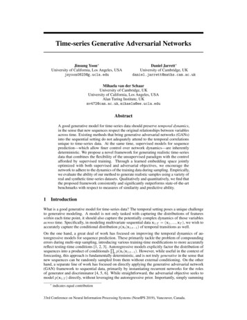
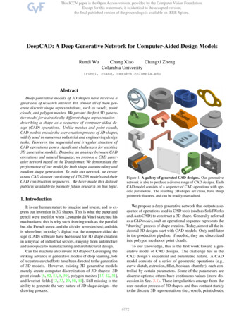
DeepCAD: A Deep Generative Network for Computer-Aided Design ModelsRundi WuChang XiaoChangxi ZhengColumbia University{rundi, chang, cxz}@cs.columbia.eduAbstractDeep generative models of 3D shapes have received agreat deal of research interest. Yet, almost all of them generate discrete shape representations, such as voxels, pointclouds, and polygon meshes. We present the first 3D generative model for a drastically different shape representation—describing a shape as a sequence of computer-aided design (CAD) operations. Unlike meshes and point clouds,CAD models encode the user creation process of 3D shapes,widely used in numerous industrial and engineering designtasks. However, the sequential and irregular structure ofCAD operations poses significant challenges for existing3D generative models. Drawing an analogy between CADoperations and natural language, we propose a CAD generative network based on the Transformer. We demonstrate theperformance of our model for both shape autoencoding andrandom shape generation. To train our network, we createa new CAD dataset consisting of 178,238 models and theirCAD construction sequences. We have made this datasetpublicly available to promote future research on this topic.1. IntroductionIt is our human nature to imagine and invent, and to express our invention in 3D shapes. This is what the paper andpencil were used for when Leonardo da Vinci sketched hismechanisms; this is why such drawing tools as the parallelbar, the French curve, and the divider were devised; and thisis wherefore, in today’s digital era, the computer aided design (CAD) software have been used for 3D shape creationin a myriad of industrial sectors, ranging from automotiveand aerospace to manufacturing and architectural design.Can the machine also invent 3D shapes? Leveraging thestriking advance in generative models of deep learning, lotsof recent research efforts have been directed to the generationof 3D models. However, existing 3D generative modelsmerely create computer discretization of 3D shapes: 3Dpoint clouds [6, 52, 53, 8, 30], polygon meshes [17, 42, 31],and levelset fields [12, 33, 29, 50, 11]. Still missing is theability to generate the very nature of 3D shape design—thedrawing process.Figure 1. A gallery of generated CAD designs. Our generativenetwork is able to produce a diverse range of CAD designs. EachCAD model consists of a sequence of CAD operations with specific parameters. The resulting 3D shapes are clean, have sharpgeometric features, and can be readily user-edited.We propose a deep generative network that outputs a sequence of operations used in CAD tools (such as SolidWorksand AutoCAD) to construct a 3D shape. Generally referredas a CAD model, such an operational sequence represents the“drawing” process of shape creation. Today, almost all the industrial 3D designs start with CAD models. Only until laterin the production pipeline, if needed, they are discretizedinto polygon meshes or point clouds.To our knowledge, this is the first work toward a generative model of CAD designs. The challenge lies in theCAD design’s sequential and parametric nature. A CADmodel consists of a series of geometric operations (e.g.,curve sketch, extrusion, fillet, boolean, chamfer), each controlled by certain parameters. Some of the parameters arediscrete options; others have continuous values (more discussion in Sec. 3.1). These irregularities emerge from theuser creation process of 3D shapes, and thus contrast starklyto the discrete 3D representations (i.e., voxels, point clouds,6772
and meshes) used in existing generative models. In consequence, previously developed 3D generative models areunsuited for CAD model generation.Technical contributions. To overcome these challenges,we seek a representation that reconciles the irregularities inCAD models. We consider the most frequently used CADoperations (or commands), and unify them in a commonstructure that encodes their command types, parameters, andsequential orders. Next, drawing an analogy between CADcommand sequences and natural languages, we propose anautoencoder based on the Transformer network [40]. It embeds CAD models into a latent space, and later decode alatent vector into a CAD command sequence. To train ourautoencoder, we further create a new dataset of CAD command sequences, one that is orders of magnitude larger thanthe existing dataset of the same type. We have also madethis dataset publicly available1 to promote future researchon learning-based CAD designs.Our method is able to generate plausible and diverse CADdesigns (see Fig. 1). We carefully evaluate its generationquality through a series of ablation studies. Lastly, we endour presentation with an outlook on useful applications enabled by our CAD autoencoder.2. Related workParametric shape inference. Advance in deep learninghas enabled neural network models that analyze geometricdata and infer parametric shapes. ParSeNet [38] decomposesa 3D point cloud into a set of parametric surface patches.PIE-NET [43] extracts parametric boundary curves from3D point clouds. UV-Net [19] and BrepNet [24] focus onencoding a parametric model’s boundary curves and surfaces.Li et al. [25] trained a neural network on synthetic data toconvert 2D user sketches into CAD operations. Recently,Xu et al. [51] applied neural-guided search to infer CADmodeling sequence from parametric solid shapes.Generative models of 3D shapes. Recent years have alsowitnessed increasing research interests on deep generativemodels for 3D shapes. Most existing methods generate 3Dshapes in discrete forms, such as voxelized shapes [49, 16,27, 26], point clouds [6, 52, 53, 8, 30], polygon meshes [17,42, 31], and implicit signed distance fields [12, 33, 29, 50,11]. The resulting shapes may still suffer from noise, lacksharp geometric features, and are not directly user editable.Therefore, more recent works have sought neural network models that generate 3D shape as a series of geometricoperations. CSGNet [37] infers a sequence of Constructive Solid Geometry (CSG) operations based on voxelizedshape input; and UCSG-Net [21] further advances the inference with no supervision from ground truth CSG trees.Other than using CSG operations, several works synthesize1 Codeand data are available here.3D shapes using their proposed domain specific languages(DSLs) [39, 41, 30, 20]. For example, Jones et al. [20] proposed ShapeAssembly, a DSL that constructs 3D shapes bystructuring cuboid proxies in a hierarchical and symmetrical fashion, and this structure can be generated through avariational autoencoder.In contrast to all these works, our autoencoder networkoutputs CAD models specified as a sequence of CAD operations. CAD models have become the standard shape representation in almost every sectors of industrial production.Thus, the output from our network can be readily importedinto any CAD tools [1, 2, 3] for user editing. It can alsobe directly converted into other shape formats such as pointclouds and polygon meshes. To our knowledge, this is thefirst generative model directly producing CAD designs.Transformer-based models. Technically, our work is related to the Transformer network [40], which was introduced as an attention-based building block for many naturallanguage processing tasks [13]. The success of the Transformer network has also inspired its use in image processingtasks [34, 9, 14] and for other types of data [31, 10, 44].Concurrent works [47, 32, 15] on constrained CAD sketchesgeneration also rely on Transformer network.Also related to our work is DeepSVG [10], a Transformerbased network for the generation of Scalable Vector Graphic(SVG) images. SVG images are described by a collectionof parametric primitives (such as lines and curves). Apartfrom limited in 2D, those primitives are grouped with no specific order or dependence. In contrast, CAD commands aredescribed in 3D; they can be interdependent (e.g., throughCSG boolean operations) and must follow a specific order.We therefore seek a new way to encode CAD commands andtheir sequential order in a Transformer-based autoencoder.3. MethodWe now present our DeepCAD model, which revolvesaround a new representation of CAD command sequences(Sec. 3.1.2). Our CAD representation is specifically tailored, for feeding into neural networks such as the proposedTransformer-based autoencoder (Sec. 3.2). It also leads to anatural objective function for training (Sec. 3.4). To train ournetwork, we create a new dataset, one that is significantlylarger than existing datasets of the same type (Sec. 3.3), andone that itself can serve beyond this work for future research.3.1. CAD Representation for Neural NetworksThe CAD model offers two levels of representation. Atthe user-interaction level, a CAD model is described as asequence of operations that the user performs (in CAD software) to create a solid shape—for example, a user maysketch a closed curve profile on a 2D plane, and thenextrude it into a 3D solid shape, which is further processedby other operations such as a boolean union with another6773
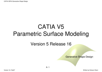
CAD construction process:Sketch 1Extrude 1Sketch 2CommandsParametershSOLiL(Line);A(Arc)Extrude 2Parametrized command sequence:R(Circle)x, y : line end-pointx, y : arc end-point : sweep anglef : counter-clockwise flagx, y : center , ,E(Extrude)Figure 2. A CAD model example specified by the commands inTable 1. (Top) the CAD model’s construction sequence, annotatedwith the command types. (Bottom) the command sequence description of the model. Parameter normalization and quantization arenot shown in this case. In “Sketch 1”, L2 -A3 -L4 -L5 forms a loop(in blue) and C7 forms another loop (in green), and the two loopsbounds a sketch profile (in gray).already created solid shape (see Fig. 2). We refer to such aspecification as a CAD command sequence.Behind the command sequence is the CAD model’s kernelrepresentation, widely known as the boundary representation (or B-rep) [45, 46]. Provided a command sequence, itsB-rep is automatically computed (often through the industrystandard library Parasolid). It consists of topological components (i.e., vertices, parametric edges and faces) and theconnections between them to form a solid shape.In this work, we aim for a generative model of CAD command sequences, not B-reps. This is because the B-rep isan abstraction from the command sequence: a commandsequence can be easily converted into a B-rep, but the converse is hard, as different command sequences may result inthe same B-rep. Moreover, a command sequence is humaninterpretable; it can be readily edited (e.g., by importingthem into CAD tools such as AutoCAD and Onshape), allowing them to be used in various downstream applications.3.1.1Specification of CAD CommandsFull-fledged CAD tools support a rich set of commands,although in practice only a small fraction of them are commonly used. Here, we consider a subset of the commandsthat are of frequent use (see Table 1). These commands fallinto two categories, namely sketch and extrusion. While conceptually simple, they are sufficiently expressive to generatea wide variety of shapes, as has been demonstrated in [48].Sketch. Sketch commands are used to specify closedcurves on a 2D plane in 3D space. In CAD terminology,each closed curve is referred as a loop, and one or moreloops form a closed region called a profile (see “Sketch 1”in Fig. 2). In our representation, a profile is described byr : radius: sketch plane orientationpx , py , pz : sketch plane origins : scale of associated sketch profilee1 , e2 : extrude distances toward both sidesb : boolean type, u : extrude typehEOSi;Table 1. CAD commands and their parameters. hSOLi indicatesthe start of a loop; hEOSi indicates the end of the whole sequence.a list of loops on its boundary; a loop always starts withan indicator command hSOLi followed by a series of curvecommands Ci . We list all the curves on the loop in counterclockwise order, beginning with the curve whose startingpoint is at the most bottom-left; and the loops in a profile aresorted according to the bottom-left corners of their boundingboxes. Figure 2 illustrates two sketch profiles.In practice, we consider three kinds of curve commandsthat are the most widely used: draw a line, an arc, and acircle. While other curve commands can be easily added(see Sec. 5), statistics from our large-scale real-world dataset(described in Sec. 3.3) show that these three types of commands constitute 92% of the cases.Each curve command Ci is described by its curve typeti 2 {hSOLi, L, A, R} and its parameters listed in Table 1.Curve parameters specify the curve’s 2D location in thesketch plane’s local frame of reference, whose own positionand orientation in 3D will be described shortly in the associated extrusion command. Since the curves in each loop areconcatenated one after another, for the sake of compactnesswe exclude the curve’s starting position from its parameterlist; each curve always starts from the ending point of its predecessor in the loop. The first curve always starts from theorigin of the sketch plane, and the world-space coordinateof the origin is specified in the extrusion command.In short, a sketch profile S is described by a list of loopsS [Q1 , . . . , QN ], where each loop Qi consists of a series of curves starting from the indicator command hSOLi(i.e., Qi [hSOLi, C1 , . . . , Cni ]), and each curve commandCj (tj , pj ) specifies the curve type ti and its shape parameters pj (see Fig. 2).Extrusion. The extrusion command serves two purposes.1) It extrudes a sketch profile from a 2D plane into a 3D body,and the extrusion type can be either one-sided, symmetric, or6774
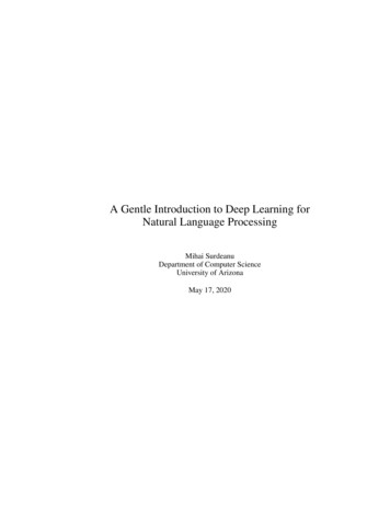
two-sided with respect to the profile’s sketch plane. 2) Thecommand also specifies (through the parameter b in Table 1)how to merge the newly extruded 3D body with the previously created shape by one of the boolean operations: eithercreating a new body, or joining, cutting or intersecting withthe existing body.The extruded profile—which consists of one or morecurve commands—is always referred to the one describedimmediately before the extrusion command. The extrusioncommand therefore needs to define the 3D orientation of thatprofile’s sketch plane and its 2D local frame of reference.This is defined by a rotational matrix, determined by ( , , )parameters in Table 1. This matrix is to align the world frameof reference to the plane’s local frame of reference, and toalign z-axis to the plane’s normal direction. In addition,the command parameters include a scale factor s of theextruded profile; the rationale behind this scale factor willbe discussed in Sec. 3.1.2.With these commands, we describe a CAD model M asa sequence of curve commands interleaved with extrusioncommands (see Fig. 2). In other words, M is a commandsequence M [C1 , . . . , CNc ], where each Ci has the form(ti , pi ) specifying the command type ti and parameters pi .3.1.2Network-friendly RepresentationOur specification of a CAD model M is akin to naturallanguage. The vocabulary consists of individual CAD commands expressed sequentially to form sentences. The subjectof a sentence is the sketch profile; the predicate is the extrusion. This analogy suggests that we may leverage thenetwork structures, such as the Transformer network [40],succeeded in natural language processing to fulfill our goal.However, the CAD commands also differ from naturallanguage in several aspects. Each command has a differentnumber of parameters. In some commands (e.g., the extrusion), the parameters are a mixture of both continuous anddiscrete values, and the parameter values span over differentranges (recall Table 1). These traits render the commandsequences ill-posed for direct use in neural networks.To overcome this challenge, we regularize the dimensionsof command sequences. First, for each command, its parameters are stacked into a 16 1 vector, whose elements correspond to the collective parameters of all commands in Table 1(i.e., pi [x, y, , f, r, , , , px , py , pz , s, e1 , e2 , b, u]).Unused parameters for each command are simply set tobe 1. Next, we fix the total number Nc of commands inevery CAD model M . This is done by padding the CADmodel’s command sequence with the empty command hEOSiuntil the sequence length reaches Nc . In practice, we chooseNc 60, the maximal command sequence length appearedin our training dataset.Furthermore, we unify continuous and discrete parameters by quantizing the continuous parameters. To this end,Learned Constant EmbeddingsAverage PoolingC1zTransformerEncoder ETransformerDecoder DEmbeddingLinearCNCC1CNCFigure 3. Our network architecture. The input CAD model, repcresented as a command sequence M {Ci }Ni 1 is first projectedto an embedding space and then fed to the encoder E resulting in alatent vector z. The decoder D takes learned constant embeddingsas input, and also attends to the latent vector z. It then outputs thecpredicted command sequence M̂ {Ĉi }Ni 1 .we normalize every CAD model within a 2 2 2 cube;we also normalize every sketch profile within its boundingbox, and include a scale factor s (in extrusion command)to restore the normalized profile into its original size. Thenormalization restricts the ranges of continuous parameters,allowing us to quantize their values into 256 levels and express them using 8-bit integers. As a result, all the commandparameters possess only discrete sets of values.Not simply is the parameter quantization a follow-up ofthe common practice for training Transformer-based networks [36, 31, 44]. Particularly for CAD models, it is crucial for improving the generation quality (as we empiricallyconfirm in Sec. 4.1). In CAD designs, certain geometric relations—such as parallel and perpendicular sketch lines—mustbe respected. However, if a generative model directly generates continuous parameters, their values, obtained throughparameter regression, are prone to errors that will break thesestrict relations. Instead, parameter quantization allows thenetwork to “classify” parameters into specific levels, andthereby better respect learned geometric relations.In Sec. 4.1, we will present ablation studies that empirically justify our choices of CAD command representation.3.2. Autoencoder for CAD ModelsWe now introduce an autoencoder network that leveragesour representation of CAD commands. Figure 3 illustratesits structure, and more details are provided in Sec. C ofsupplementary document. Once trained, the decoder part ofthe network will serve naturally as a CAD generative model.Our autoencoder is based on the Transformer network,inspired by its success for processing sequential data [40,13, 28]. Our autoencoder takes as input a CAD commandsequence M [C1 , · · · , CNc ], where Nc is a fixed number(recall Sec. 3.1.2). First, each command Ci is projectedseparately onto a continuous embedding space of dimensiondE 256. Then, all the embeddings are put together tofeed into an encoder E, which in turn outputs a latent vectorz 2 R256 . The decoder takes the latent vector z as input,6775
and outputs a generated CAD command sequence M̂ .Embedding. Similar in spirit to the approach in naturallanguage processing [40], we first project every commandCi onto a common embedding space. Yet, different fromwords in natural languages, a CAD command Ci (ti , pi )has two distinct parts: its command type ti and parameterspi . We therefore formulate a different way of computing theembedding of Ci : take it as a sum of three embeddings, thatdEis, e(Ci ) ecmd eparam eposiii 2R .cmdThe first embedding ei accounts for the command typeti , given by ecmd Wcmd ic . Here Wcmd 2 RdE 6 is ailearnable matrix and ic 2 R6 is a one-hot vector indicatingthe command type ti among the six command types.The second embedding eparamconsiders the commandiparameters. As introduced in Sec. 3.1.2, every commandhas 16 parameters, each of which is quantized into an 8-bitinteger. We convert each of these integers into a one-hotpvector i,j(j 1.16) of dimension 28 1 257; theadditional dimension is to indicate that the parameter isunused in that command. Stacking all the one-hot vectorsinto a matrix ip 2 R257 16 , we embed each parameterbseparately using another learnable matrix Wparam2 RdE 257 ,and then combine the individual embeddings through a linearalayer Wparam2 RdE 16dE , namely,abeparam Wparamflat(Wparamipi ),(1)where flat(·) flattens the input matrix to a vector.Lastly, similar to [40], the positional embedding eposi is toindicate the index of the command Ci in the whole commanddE Ncsequence, defined as eposi Wpos i , where Wpos 2 RNcis a learnable matrix and i 2 R is the one-hot vectorfilled with 1 at index i and 0 otherwise.Encoder. Our encoder E is composed of four layers ofTransformer blocks, each with eight attention heads andfeed-forward dimension of 512. The encoder takes the embedding sequence [e1 , ., eNc ] as input, and outputs vectors[e01 , ., e0Nc ]; each has the same dimension dE 256. Theoutput vectors are finally averaged to produce a single dE dimensional latent vector z.Decoder. Also built on Transformer blocks, our decoder Dhas the same hyper-parameter settings as the encoder. It takesas input learned constant embeddings while also attendingto the latent vector z—similar input structure has been usedin [9, 10]. Output from the last Transformer block is fedinto a linear layer to predict a CAD command sequenceM̂ [Ĉ1 , ., ĈNc ], including both the command type t̂iand parameters p̂i for each command. As opposed to theautoregressive strategy commonly used in natural languageprocessing [40], we adopt the feed-forward strategy [9, 10],and the prediction of our model can be factorized asp(M̂ z, ) NcYi 1p(t̂i , p̂i z, ),(2)where denotes network parameters of the decoder.3.3. Creation of CAD DatasetSeveral datasets of CAD designs exist, but none of themsuffice for our training. In particular, the ABC dataset [23]collects about 1 million CAD designs from Onshape, a webbased CAD tool and repository [3]. Although this is a largescale dataset, its CAD designs are provided in B-rep format,with no sufficient information to recover how the designsare constructed by CAD operations. The recent Fusion 360Gallery dataset [48] offers CAD designs constructed by profile sketches and extrusions, and it provides the CAD command sequence for each design. However, this dataset hasonly 8000 CAD designs, not enough for training a wellgeneralized generative model.We therefore create a new dataset that is large-scale andprovides CAD command sequences. Apart from using it totrain our autoencoder network, this dataset may also servefor future research. We have made it publicly available.To create the dataset, we also leverage Onshape’s CADrepository and its developer API [4] to parse the CAD designs. We start from the ABC dataset. For each CAD model,the dataset provides a link to Onshape’s original CAD design.We then use Onshape’s domain specific language (called FeatureScript [5]) to parse CAD operations and parameters usedin that design. For CAD models that use the operations beyond sketch and extrusion, we simply discard them. For therest of the models, we use a FeatureScript program to extractthe sketch profiles and extrusions, and express them usingthe commands listed in Table 1.In the end, we collect a dataset with 178,238 CAD designsall described as CAD command sequences. This is ordersof magnitude larger than the existing dataset of the sametype [48]. The dataset is further split into training, validationand test sets by 90%-5%-5% in a random fashion, ready touse in training and testing. Figure 9 in the supplementarydocument samples some CAD models from our dataset.3.4. Training and Runtime GenerationTraining. Leveraging the dataset, we train our autoencodernetwork using the standard Cross-Entropy loss. Formally,we define the loss between the predicted CAD model M̂ andthe ground truth model M asL NcXi 1 (t̂i , ti ) NPNc XX (p̂i,j , pi,j ),(3)i 1 j 1where (·, ·) denotes the standard Cross-Entropy, Np is thenumber of parameters (Np 16 in our examples), andis a weight to balance both terms ( 2 in our examples).Note that in the ground-truth command sequence, somecommands are empty (i.e., the padding command hEOSi)and some command parameters are unused (i.e., labeled as6776
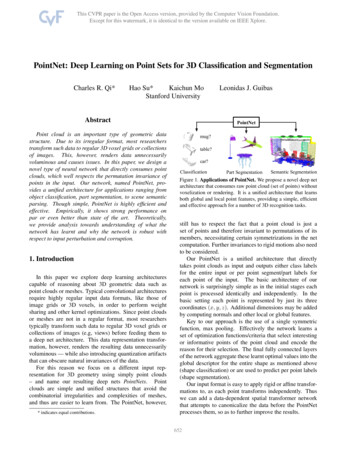
MethodOurs AugOursAlt-ArcMidAlt-TransAlt-RelAlt-RegrACCcmd "ACCparam 2.1422.723.303.263.303.514.32Table 2. Quantitative evaluation of autoencoding. ACCcmd andACCparam are both multiplied by 100%, and CD is multiplied by103 . ": a higher metric value indicates better autoencoding quality.#: a lower metric value is better. ACC values for Alt-Regr are notavailable since Alt-Regr does not use quantized parameters.1). In those cases, their corresponding contributions to thesummation terms in (3) are simply ignored.The training process uses the Adam optimizer [22] witha learning rate 0.001 and a linear warm-up period of 2000initial steps. We set a dropout rate of 0.1 for all Transformer blocks and apply gradient clipping of 1.0 in backpropagation. We train the network for 1000 epochs with abatch size of 512.CAD generation. Once the autoencoder is well trained,we can represent a CAD model using a 256-dimensional latent vector z. For automatic generation of CAD models, weemploy the latent-GAN technique [6, 12, 50] on our learnedlatent space. The generator and discriminator are both assimple as a multilayer perceptron (MLP) network with fourhidden layers, and they are trained using Wasserstein-GANtraining strategy with gradient penalty [7, 18]. In the end,to generate a CAD model, we sample a random vector froma multivariate Gaussian distribution and feeding it into theGAN’s generator. The output of the GAN is a latent vectorz input to our Transformer-based decoder.4. ExperimentsIn this section, we evaluate our autoencoder networkfrom two perspectives: the autoencoding of CAD models(Sec. 4.1) and latent-space shape generation (Sec. 4.2). Wealso discuss possible applications that can benefit from ourCAD generative model (Sec. 4.3).There exist no previous generative models for CAD designs, and thus no methods for our model to direct comparewith. Our goal here is to understand the performance of ourmodel under different metrics, and justify the algorithmicchoices in our model through a series of ablation studies.4.1. Autoencoding of CAD ModelsThe autoencoding performance has often been used toindicate the extent to which the generative model can expressthe target data distribution [6, 12, 17]. Here we use ourautoencoder network to encode a CAD model M absentAltRegrAltRelAltTransAltArcMidOursOurs AugGTFigure 4. Comparison of autoencoding results. Hidden edges arealso rendered visible (white). Ground truth (GT) is shown in thebottom row. Our best results are highlighted in the dash-line box.from the training dataset; we then decode the resulting latentvector into a CAD model M̂ . The autoencoder is evaluatedby the difference between M and M̂ .Metrics. To thoroughly understand our autoencoder’s performance, we measure the difference between M and M̂in terms of both the CAD commands and the resulting 3Dgeometry. We propose to evaluate command accuracy using two metrics, namely Command Accuracy (ACCcmd ) andParameter Accuracy (ACCparam ). The former measures thecorrectness of the predicted CAD command type, defined asACCcmdNc1 X I[ti t̂i ].Nc i 1(4)Here the notation follows those in Sec. 3. Nc denote the totalnumber of CAD commands, and ti and t̂i are the groundtruth and recovered command types, respectively. I[·] is theindicator function (0 or 1).Once the command type is correctly recovered, we alsoevaluate the correctness of the command parameters. This iswhat Parameter Accuracy (ACCparam ) is meant to measure:ACCparam 6777 p̂i Nc X1 XI[ pi,jK i 1 j 1p̂i,j ]I[ti t̂i ], (5)
PNcwhere K i 1I[ti t̂i ] pi is the total number of parameters in all correctly recovered commands. Note thatpi,j and p̂i,j are both quantized into 8-bit integers. is chosen as a tolerance threshold accounting for the parameterquantization. In practice, we use 3 (out of 256 levels).To measure the quality of recovered 3D geometry, weuse Chamfer Distance (CD), the metric used in many previous generative models of discretized shapes (such as pointclouds) [6, 17, 12]. Here, we evaluate CD by uniformlysampling 2000 points on the surfaces of reference shape andrecovered shape, respectively; and measure CD between thetwo sets of points. Moreover, it is not guaranteed that theoutput CAD command sequence always produces a valid 3Dshape. In rare cases, the output commands may lead to aninvalid topology, and thus no point cloud can be extractedfrom that CAD model. We therefore also report the InvalidRatio, the percentage of the output CAD models that fail tobe converted to point clouds.Comparison methods. Due to the lack of existing CADgenerative models, we compare our model with several variants in order to justify our data representation and trainingstrategy. In particular, we consider the following variants.Alt-Rel represents curve positions relative to the positionof its predecessor curve in the loop. It contrasts to our model,which uses absolute positions in curve specification.Alt-Trans includes in the extrusion command the starting point position of the loop (in addition to the origin ofthe sketch plane). Here the starting point position and theplane’s origin are in the world frame of reference of theCAD model. In contrast, our proposed method includes onlythe sketch plane’s origin, and the origin is translated to theloop’s starting position—it is therefore more compact.Alt-ArcMid specifies an arc using its ending and middlepoint positions, but not the sweeping angle and the counterclockwise flag used in Table 1.Alt-Reg
DeepCAD: A Deep Generative Network for Computer-Aided Design Models Rundi Wu Chang Xiao Changxi Zheng Columbia University {rundi, chang, cxz}@cs.columbia.edu Abstract Deep generative models of 3D shapes have received a great deal of research interest. Yet, almost all of them gen-er