Transcription
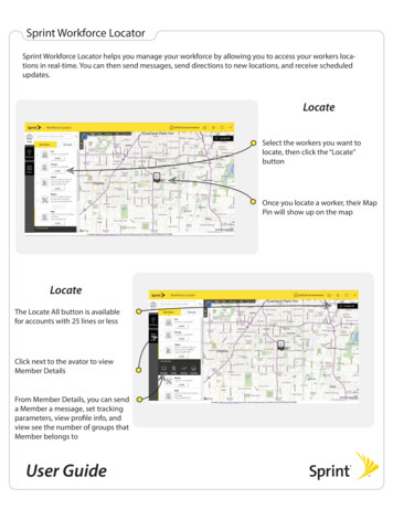
Paper Session: 3DUIST’11, October 16–19, 2011, Santa Barbara, CA, USA6D Hands: Markerless Hand Trackingfor Computer Aided DesignRobert Y. Wang1,3, Sylvain Paris2 , Jovan Popović2,4123Gear SystemsAdobe Systems, Inc.Foster City, CACambridge, MArywang@threegear.com {sparis,jovan}@adobe.com3MIT CSAILCambridge, MAExperimental setupABSTRACTComputer Aided Design (CAD) typically involves tasks suchas adjusting the camera perspective and assembling piecesin free space that require specifying 6 degrees of freedom(DOF). The standard approach is to factor these DOFs into2D subspaces that are mapped to the x and y axes of a mouse.This metaphor is inherently modal because one needs to switchbetween subspaces, and disconnects the input space from themodeling space. In this paper, we propose a bimanual handtracking system that provides physically-motivated 6-DOFcontrol for 3D assembly. First, we discuss a set of principles that guide the design of our precise, easy-to-use, andcomfortable-to-use system. Based on these guidelines, wedescribe a 3D input metaphor that supports constraint specification classically used in CAD software, is based on onlya few simple gestures, lets users rest their elbows on theirdesk, and works alongside the keyboard and mouse. Ourapproach uses two consumer-grade webcams to observe theuser’s hands. We solve the pose estimation problem with efficient queries of a precomputed database that relates handsilhouettes to their 3D configuration. We demonstrate efficient 3D mechanical assembly of several CAD models usingour hand-tracking system.4Univ. of WashingtonSeattle, WACamea inputs Pose estimates3D assembly task controlled with hand-trackingFigure 1: We propose a markerless hand-tracking system using two webcams for 3D assembly in the contextof Computer Aided Design.H5.2 [Information Interfaces and Presentation]: User Interfaces–Input devices and strategiesACM Classification:General terms:nents of a translation or the three angles of a rotation. However, a 2D mouse is still the predominate method by whichusers interact with CAD software. It is typically controlledunimanually by the dominant (right) hand and used for bothadjusting the camera perspective and moving objects in a 3Dscene. In this paper, we propose a new input method that iscomplimentary to the mouse and better matches the dimensionality of 3D assembly tasks.Design, Human Factors, Algorithmscomputer aided design, hand-tracking, 3D object manipulationKeywords:INTRODUCTIONComputer Aided Design (CAD) is an essential component ofmodern mechanical engineering, architectural design and visual effects design. 3D CAD software enables a user to digitally specify shapes, positions and orientations of objects in avirtual 3D scene. Formally, most of these tasks require usersto specify 3 or more variables, for instance, the xyz compo-We facilitate more efficient interactions for CAD by enablingthe user to manipulate the camera perspective and objects inthe scene with both hands in 3D. We can track 6 degrees offreedom for each hand and a pinching gesture for selection.To avoid wrist-strain, we primarily use the three translationaldegrees of freedom of each hand tracked at the tip of thethumb. We propose comfortable, memorable and efficientgestures that map unimanual translation to 3D translation inthe virtual world and bimanual translation to 3D rotation.Permission to make digital or hard copies of all or part of this work forpersonal or classroom use is granted without fee provided that copies arenot made or distributed for profit or commercial advantage and that copiesbear this notice and the full citation on the first page. To copy otherwise, torepublish, to post on servers or to redistribute to lists, requires prior specificpermission and/or a fee.UIST’11, October 16-19, 2011, Santa Barbara, CA, USA.Copyright 2011 ACM 978-1-4503-0716-1/11/10. 10.00.A complete CAD software system typically includes functionality for modeling 3D parts, assembling the parts into549
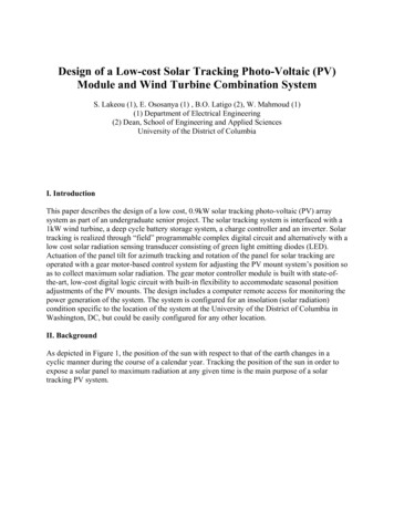
Paper Session: 3DUIST’11, October 16–19, 2011, Santa Barbara, CA, USAa whole, and, in the case of engineering CAD, laying outviews of the assembly on a paper blueprint. In this work, wefocus on the assembly component of CAD, which primarilyinvolves the 3D positioning of parts, a task well suited fordirect hand manipulation.surface. In organic set dressing, the artistic look and feel ofa scene is more important than precise placement of parts.In comparison, we focus primarily on 3D assembly for mechanical engineering where exact relationships between partsis crucial.A major feature of our system is that it tracks the hands without gloves or markers, leaving them unencumbered to use thekeyboard and mouse. This enables users to transition seamlessly to existing functionality in the CAD software such asnavigating a menu with the mouse and typing coordinates onthe keyboard. By facilitating these mixed-mode operations,our system serves as a practical complement to the mouseand keyboard for 3D assembly interactions.A large body of HCI research has used various forms of 3Dinput for virtual reality applications [1, 10, 3] but studies haveshown that 3D input usability is often inferior to the mouse[5, 23]. Based on this observation, we designed our systemto limit the duration of 3D input sessions and to be complementary to existing input devices so that users can fall back tostandard mouse keyboard interaction at any time. We envision that our hand tracking will be used only for 3D assemblytasks where it offers a natural and intuitive three-dimensionalinteraction, while other tasks such as menu navigation willcontinue to be done with the mouse.RELATED WORKMany methods have been proposed for markerless or gloveless hand tracking, but they are either too slow for interactiveapplications, e.g. [24, 7], or the range of poses that they candetect do not permit the precise selection required in CADapplications, e.g. [14, 13, 20]. In comparison, our systemachieves bimanual 6-DOF pose estimation at interactive ratesand reliably detects poses suited for discrete selection such aspinching and pointing.TRADITIONAL 3D ASSEMBLY WORKFLOW3D assembly refers to positioning a set of 3D parts to createa larger whole. It is used to construct a set from a collectionof props or to assemble mechanical pieces into a machine. Itis performed in two main ways.Coarse 3D placement is used primarily in the context of computer animation or special effects, where the location of anobject is only important so much as it generates a convincingimage or effect. For such placement, users mostly rely onthe translation manipulator to specify position in 3D spacewith a 2D mouse. A translation manipulator multiplexes 3Dtranslation onto three 1D components projected as axes onthe screen (Figure 2). The user selects an arrow and dragsalong each axis, one at a time, to move an object to its desired location. CAD software also lets users drag objectsfreely in the image plane. These manipulators are good atspecifying axis-aligned and in-plane translations, but requiremore effort for other directions. Equivalent metaphors withsimilar pros and cons exist for rotations.Glove tracking has been proposed to ease and speed up theproblem of hand tracking, e.g. [27, 25]. However, gloves area significant drawback if one wants to also use the keyboardand mouse. Users may be reluctant to put on a glove whenswitching from a 2D task such as menu navigation to a 3Dtask such as object assembly. Wearing a glove may also become uncomfortable during long work sessions.Dedicated 6-DOF rate-control devices such as the 3DConnexion SpaceNavigator are used for smooth camera control,but are generally not suited for or used for object selection ormanipulation in CAD. We propose a set of hand gestures thatworks well for both camera adjustment and object manipulation.YRecently Microsoft introduced and deployed the Kinect motion capture system. While successful results have beenshown for whole body tracking [21], it is unclear if the Kinectsystem can be used to track hands. In particular, occlusionsof the fingers are difficult to resolve using a single viewpoint.Pinching has been shown to be an effective gesture for “clicking” in 3D space. Hilliges and colleagues use a single depthcamera to detect pinches above a table top [9]. Benko andWilson [4] track pinches using an infrared camera above aprojector. Wilson uses a webcam to detect pinches abovethe keyboard [26]. However, all three approaches rely ona single-view pinch detection technique that suffers from occlusions, restricting the hand orientations that can be tracked.A unique feature of our approach is the use of two widebaseline viewpoints. Our two-view approach resolves occlusions from one view using information from the other, enabling robust gesture (e.g. pinch) detection. Our contributionis independent of the particular type of camera used (depthor RGB).ZXFigure 2: A traditional translation manipulator multiplexes 3D translation onto three 1-D translation modes.The user enters the x translation mode by draggingalong the projected x-axis.These manipulators provide a continuous and thus imprecise translation control. For precise placement of mechanical parts, a process of specifying constraints between facesand boundaries (or “mates”) is used to define the position ofa part exactly. Such positioning is crucial in manufacturing,and mating is the primary mode for 3D assembly in all mechanical engineering CAD software (e.g. SolidWorks, Autodesk Inventor, CATIA). A mate is specified with the mouseby selecting two of the features to align, and defining theRecent work on 3D assembly by Kin and colleagues [11]addressed the construction of organic sets on a multi-touch550
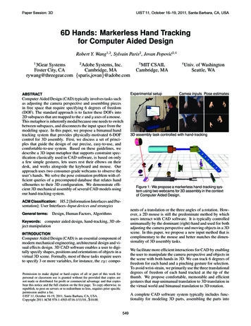
Paper Session: 3DUIST’11, October 16–19, 2011, Santa Barbara, CA, USArelationship between them (Figure 3). For instance, if twocircular boundaries are required to lie along the same axis, auser would click each boundary successively and select theconcentric mate option. Specifying mates requires significant adjustments to the camera perspective because mates often involve occluded features. For instance, when specifyingthat two faces should be coincident, one of the faces is oftenfacing away from the user, and thus not directly selectable.1 Select first face2 Rotate camera3 Select second face4 Coincident mateDesign PrinciplesBefore describing the gestures that we implemented in oursystem, we first discuss the challenges that we faced whilewe designed our system and the high-level principles that wefollowed to address them.Although a humanhand has 27 DOFs, only a few poses are comfortable andcan be reproduced without training. Guided by this idea, webuilt our system mostly on the pinch pose inspired by Andrew Wilson’s [26] Thumb and Fore-Finger Interface. Weuse pinching as an analog of the mouse click to indicate theselection of an object. We also explore pointing for specifying remote locations, and touching the desktop with fingersto turn the desk surface into a multi-touch interface.A small number of simple hand posesTo create preciseand memorable gestures, we use metaphors that correspondclosely to physical actions. We directly map 3D physical positions to virtual positions. Once a user understands a virtualscene, reaching for the object leverages his physical intuitionto reach for a point in 3D space. We also adopt a physicallybased mental model to design hand gestures for rotation. Motivated by work showing that users tend to perform rotationand translation separately [15], we decouple camera rotationand camera translation as two distinct gestures to provideprecise and physically-based control for both.Use precise and memorable gesturesFigure 3: To specify a constraint or “mate" using a traditional 2D mouse, the user clicks on one face, rotatesthe camera, clicks on the other face, and indicates thatthey should be coincident.In addition to manipulating objects, users also adjust thecamera perspective to visualize the assembly from differentview points or to select occluded features. This is classicallydone with the mouse using an arcball rotation control. Thistool maps x and y mouse translations to the rotations aroundthe y and x screen axes respectively. z-axis rotation, whenavailable, is modal and involves either a different mouse button or a modifier key.Unrestricted 3D interactions and largemovements are tiring and only useful for short periods oftime. We exploit the desktop environment to address the fatigue issue and design our system such that users can resttheir elbows or forearms on the desk most of the time. Inspired by the Eden system, [11], we also allow the user topass objects between the hands (throw-and-catch) to minimize dragging. We also amplify the user’s 3D motion so thatonly small gestures are needed, e.g. we map a 10 hand rotation to 20 in the modeler.Limited hand motionWe observed several mechanical engineers using the Solidworks 2009 CAD software. Other functions often used in3D assembly include importing parts from the file systeminto the scene, hiding or isolating parts in complex assemblies, and performing specialized shape modifications to apart (e.g. adding threads to a screw). These actions are accessed through mouse-driven menus, and would be more difficult to map to hand tracking.Exact constraints, or mates,are crucial in mechanical engineering applications to alignpieces or put objects in exact contact. Specifying these matesexplicitly involves selecting small features such as boundaries and faces. This is already challenging in 2D with amouse, and even more difficult with 3D selection. Instead,we “snap” a part into place when it is sufficiently close tosatisfying a concentric or a coincident mate. This featureenables our prototype CAD system to facilitate the precisealignment and contact specification required in mechanicalengineering.Specification of exact constraintsWe contribute a system that uses hand gestures for the positioning of parts for 3D assembly while other tasks such asentry of numerical values, annotations, or menu navigationare still performed with the keyboard and the mouse. Ourgestures allow users to efficiently reposition pieces in 3D byselecting and moving them with their hands. Users can alsoadjust the camera perspective to access pieces and explorethe 3D scene. Furthermore, our system enables modelessspecification of exact relationships, making it suitable for theassembly of mechanical parts for engineering.Concentric and coincident mates account for a large proportion of mates between mechanical parts. For instance, anymechanical assembly held together by screws and nuts useconcentric and coincident mates. However, we hope to address more general mates (e.g. distance mates, curved surfaces) in future work. Presently, we fall back to traditionalmouse and keyboard input for more complex mates.HAND GESTURES FOR 3D ASSEMBLYBased on the observations made in the previous section, wefirst describe the design principles that guided how we builtour system. Then, we propose a set of gestures that followthese guidelines.We need to provide visual cuesthat relate the physical space where the user’s hands are withthe virtual space where modeling occurs. Since we do notCues for 3D positioning551
Paper Session: 3DUIST’11, October 16–19, 2011, Santa Barbara, CA, USAwant to assume that a 3D display is available, a simple “3Dpointer”, e.g. a small 3D arrow, is not enough because of thedepth ambiguity inherent in 2D displays that makes it difficult to know if the pointer is at the same depth as anotherobject. We address this challenge with a shadow metaphorthat provides unambiguous depth cues in addition to the main3D view. We render a virtual ground plane on which eachpiece projects a shadow, and we augment our pointer witha stem and base that shows its projection on the same plane[8], thereby resolving the depth ambiguity. Further, we alsohighlight the closest object to each hand to show which object can be selected in the current configuration.Camera and object rotation The user can control rotationby pinching with both hands, using a new sheet-of-papermetaphor. The motion is inspired by the grab-and-twirl gesture developed by Cutler and colleagues [6], and reproduceswhat users would experience if they were handling a sheet ofpaper as shown in Figure 5. Compared to grab-and-twirl, weremove the dependence on the hand orientation completely.Because we can track the 3D pinch points more accuratelythan hand orientation, we can amplify the rotated angles tominimize motion. We detail the formulas to derive the rotation angles from these gestures in the appendix.When nothing is selected, a two-handed pinch rotates theviewpoint direction. When an object is selected with oneof the hands, the rotation affects that object. Because CADmodels are almost always axis-aligned, we snap object rotations to 90 degree increments.Seamless transition between tracking and other modalities3D assembly in CAD software is performed in conjunctionwith other activities that require the use of the keyboard andmouse such as structural analysis, reading documentation, oreven just checking e-mail. Hand tracking should not interfere with other input modalities and should be an addition tothem, not a replacement. We designed our system so that itcan track bare hands since gloves and markers would impedethe users’ ability to type and use a mouse comfortably. Wealso automatically stop tracking when the hands approachthe keyboard or the mouse, which allows the user to seamlessly go back to a classical keyboard-and-mouse interactionat any time.We also experimented with a direct mapping ofhand orientation to camera and object rotation. Direct orientation mapping worked well for small rotations, but large rotations led to significant strain on the wrists. This was problematic because camera viewpoint changes and object reorientations in CAD typically involve rotations of 90 degrees ormore. In comparison, our two-handed pinching gestures donot require uncomfortable extreme wrist rotations and distributes effort across the larger muscles of the arm. Overall,we found our sheet-of-paper metaphor as easy-to-learn as adirect mapping while being more accurate and less strainingon the wrists.DiscussionGesturesWe support several gestures for object and camera manipulation (Figure 4). These are designed according the guidelinespreviously discussed.Object PlacementWhen the user pinches with one hand,we select the closest object, and translate according to thepinching hand. If the user drags the object sufficiently closeto another object, we examine the shapes of both objects andconsider snapping the dragged object to generate a mate.Camera TranslationObject translationx2Unimanual pinch and dragBimanual double-pinch and dragThrow and CatchIn our prototype CAD system, we focus on two commonmates, concentric mates between circular boundaries and coincident mates between two faces. We detect approximatealignment of circular boundaries [16, 12] to snap the objectinto an exact alignment. Similarly, we snap together parallelfaces that are almost touching to generate a coincident mate.Our 3D snapping generalizes snapping with 2D input devices[17] by generating the same mates used in CAD software.While translating an object12Pinch with other handRelease objectFigure 4: We support a few simple gestures for 3Dmanipulation and camera adjustmentLong-distance object translation Dragging objects is suitable for small translations but becomes tedious for large displacements, for example to go from one side of the workspaceto the other. We address this with a throw-and-catch gestureakin to the Eden system [11]. The user pinches with onehand next to an object, which selects it, then pinches withthe other hand where the object should go, and finally opensagain the first hand, i.e. stops pinching, which transports theobject where the second hand is. This gesture may be betterseen in the companion video.MARKERLESS HAND-TRACKINGThe main technical contribution of this work is a markerless hand tracking system that accurately and robustly recognizes the gestures previously described. As discussed inthe previous work section, real-time markerless hand tracking is still an unsolved problem, and our approach leverages awide-baseline camera setup, our constrained set of gestures,and the calibrated desktop environment to make this problemtractable.When the user double-pinches with thetwo hands, we “attach” the camera to the two hands andtranslate it according to the average hand motion.Physical SetupCamera translationWe designed our setup with several factors in mind. We ensure that both cameras can see the hands over a large 3D552
Paper Session: 3DUIST’11, October 16–19, 2011, Santa Barbara, CA, USACamera FrustumsBimanual RotationCamera 1 PerspectiveCamera 2 Perspectiveabout x-axisabout y-axisFigure 7: Our cameras are arranged so that both cameras observe the hand in a rectangular operating region (green).about z-axisFigure 5: We mimic the physical actions of rotatingan imaginary piece of paper with two hands to defineour gestures for bimanual rotation. Rotating the sheetabout the y or z -axis involves moving the hands inopposite directions along the xz or xy -plane respectively. To rotate the paper about the x-axis, one lifts orlowers the hands while bending the wrists (resulting ina translation along the y -axis about the elbow pivot)al. [25]. However, using Wang’s color glove would greatlyimpede users’ interaction with other input devices such asa mouse or a keyboard, and we opted for a markerless approach, which makes the tracking problem much more challenging. We extend Wang’s technique in several ways to address our needs and leverage our specific configuration. First,we sample only the limited set of hand poses relevant to ourgestures rather than arbitrary configurations of the hand. Wealso consider only comfortable hand orientations and positions within our rectangular area. Finally, we modify thepose estimation algorithm to use two cameras rather thanone.capture volume. Our pose estimation algorithm benefits fromtwo significantly different viewpoints to maximize information and minimize self-occlusion of the hand. The camerasare placed so that one hand does not occlude the other fromeither view. In particular, this could be a problem when onehand is raised above the other (Figure 6).Shallower ageSteeper cameraGroundTruthh2h15cm5cmθ120cmθ220cmImage Pair(Our Method)Figure 6: The most common occlusion case is whenone hand (approximated as the circle on the right) israised above another (the left circle). A steeper camera angle θ2 θ1 allows a larger vertical separationh2 h1 between the hands without occlusion.Given these constraints, we propose a configuration such thata 34cm 46cm 24cm rectangular operating region is completely visible from both cameras. The cameras are placedso that their principal axes differ by an angle of 45 , whichyields significantly different viewpoints. Each camera alsoforms a steep 67 angle with the ground plane. Given a spacing of 20 cm between the two hands, this allows one hand tobe 10 cm above the other without inter-hand occlusion.Figure 8: Given only silhouette data, a single camera view does not provide information to resolve ambiguities in orientation and finger configuration. Twocameras from different view points provides much lessambiguous data.Markerless Pose EstimationOur technique applies a data-driven pose estimation algorithm inspired by the marker-based technique of Wang etOur system builds upon recent work in data-driven pose estimation that uses a precomTwo Camera Pose Estimation553
Paper Session: 3DUIST’11, October 16–19, 2011, Santa Barbara, CA, USArespond to actions in our CAD system. While the work ofWang and colleagues sampled a large variety of hand posesfor general purpose tracking, we restrict our sampling to onlythe set of relevant hand poses for our gestures and for ourparticular desktop environment.puted database to map image features to poses, e.g. [2, 19].Specifically we adapt a technique designed to track colorgloves using a database that maps tiny 40 40 pixel imagesof the hand to their associated 3D poses [25].For background subtraction, we build a Gaussian mixturemodel for the background [22] and segment the two largestconnected skin-toned regions (from the left and right hand).We encode the hand regions from each camera as a pair oftiny images, and query for the nearest neighbors in a precomputed database mapping hand image pairs to their associated3D poses. Finally, we solve a 6-DOF inverse kinematics (IK)problem to place the resulting 3D hand pose to match thehand region locations (Figure 9).Our technique concentrates on the finger configurations required by our gestures. We use a relaxed hand pose, a pinching hand pose, and a pointing hand pose as a finger configuration basis {qi }. We then take pairwise blends betweeneach of these poses {q q αqi (1 α)qj } for α [0, 1]to generate a dense set of finger configuration transitions between basis poses.Our model assumes that the hand is in a 34cm 46cm 24cmbox above the keyboard, and we only sample hand positionsin this region. The principal axis of the hand can move ina cone subtending an angle of θ 60 and the hand cantwist about that axis φ 130 . While most people can twisttheir hands more, these ranges are sufficient to cover the setof comfortable poses. With this restrictive sampling, we areable to make markerless hand-tracking feasible.Maximum Approximation Error (pixels)A pair of hand images from different viewpoints providesmuch more information than a single image, but storing adatabase of image pairs requires twice as much memory forthe same density of hand poses. To reduce memory usage, weexploit the redundancy of hand images of the image pair set.Given a set of N 2.1 106 relevant hand poses, we renderthese poses from two camera viewpoints to obtain tiny imagepairs {(r0i , r1i )}1.N . We then sample K 30,000 of themost different (i.e. least redundant) images from these image pairs {r k }1.K using low dispersion sampling. These Kimages approximate the original set of image pairs, mappingthem to a much smaller set of approximations {(r̃0i , r̃1i )}i ,thus making image-pair-based pose estimation efficient.Image Approximation Error vs # SampledMaximum Approximation Error (pixels)10Pair SamplingOur Sampling86Effect of Gesture and Desktop Specific Sampling onImage Approximation Error18All Hand Configs16Gesture Specific Configs, All Orientations14Gesture and Desktop Specific Sampling(Our Method)12108642(lower is better)00500010000415000200002500030000# Images SampledFigure 11: Our gesture-specific and desktop-specificsampling allows us to use as much as 80% fewer samples to achieve equal sampling quality with a gestureand desktop agnostic approach.20050001000015000200002500030000# Images SampledIn Figure 11, we quantify the benefits of our gesture-specific,desktop-specific sampling, compared to sampling all handconfigurations and all orientations, many of which are impossible given the user and camera placement. A gestureagnostic sampling requires 30,000 samples to achieve equalquality with 5,000 samples taken with our approach. Adesktop-agnostic sampling requires 30,000 samples to achieveequal quality with 15,000 samples from our approach.Figure 10: We compared our proposed image sampling approach that exploits redundancy between cameras and decouples sampling with a naive approachthat samples pairs of images. Our approach yields asavings of 27% for equal quality at 30,000 samples.We compared our sampling approach to a naive image-pairsampling approach that does not exploit redundancy of images between cameras (See Figure 10). Both curves convergeslowly, but to achieve equal quality with 30,000 samplesfrom the naive approach, our approach only requires 22,000samples. To achieve equality quality with 30,000 samplestaken with our approach, the naive approach would require50% more samples (45,500).A robust pinch detector is the basisof our gestures, and we address it separately from 3D tracking. Our pinch detection is based on detecting separation ofthe tips of the index finger and thumb in at least one of thetwo camera images. First, we check for extrema [18] of thesilhouette close to the predicted locations of the index fingerand thumb from our 3D pose estimate. Thumb-index separation is detected if the geodesic distance between the extremais longer than the Euclidean distance. If no separation is detected in either view, we register a pinch (Figure 12).Pinch / Click DetectionBecause our system relies on only a few gestures, we only need to track asmall set of hand poses. Hand poses outside of this relevant set are ignored during tracking because they do not corGesture and Desktop-Specific Sampling554
Paper Session: 3DUIST’11, October 16–19, 2011, Santa Barbara, CA, USADatabaseLook upCamera ImagesSegmented HandsTiny Image PairNearestNeighborsEstimatedPose ResultFigure 9: We segment the hands using background subtraction and skin-tone detection. We take the resulting handregions and encode them as tiny images. We use a pair of tiny images to query the database, blend the nearestneighbors, and solve a 6-DOF IK problem to obtain the 3D hand pose.sampling is specific to the camera setup and needs to be regenerated when the cameras are moved. This requires approximately 30 minutes.For best results, we also manually calibrate three hand posesof the user. Differently shaped hands tend to pinch and pointdifferently. We kinematically adjust the joint angles of ourbasis poses to reflect the user-specific pinching, pointing andresting gestures. This takes approximately ten minutes ofmanual calibration, and we hope to incorporate a more accurate and automatic technique in the futu
of Computer Aided Design. nents of a translation or the three angles of a rotation. How-ever, a 2D mouse is still the predominate method by which users interact with CAD software. It is typically controlled u