Transcription
Application Note 107Understanding LED dimmingIntroductionDimming is an important requirement in the lightingindustry.It is useful for saving energy as well as creating anambiance for the space being lit.As LED lighting continues to take market share fromtraditional lighting, these LED systems are expected tooffer high performance dimming, in addition to all theadvantages of solid state lighting, with the existinginstalled base of dimmers of various types.In this application note we cover the various dimmingscheme used in the lighting industry and address theissues that may be encountered and how to solve someof the most commonly seen problems.Concept of dimmingIt is important to mention at the outset that dimmingperformance is dependent on the end user experience.Dimming level in Constant Current LED drivers is set bythe output current driving the LEDs. This current level istranslated into a light level by the LEDs. But themeasured light level is perceived by the human eye at adifferent brightness level. It is the perceived light levelthat matters the most since it is the light that is visible tothe users for the application in question.Dimming means different things to different people. LEDdriver designers refer to the drive current, fixturedesigners use the measured lumen output and end usersevaluation is based on the perceived light ie the light thatthe eye sees.Methods of dimming and DimmertypesThere are several dimming methods in use in the lightingindustry today.Lighting designers will encounter on the premises, someor all of the dimmer types discussed below. ERP Power, LLC-1-Traditionally dimming has been accomplished withdimmers that modify the AC input signal going into thelighting fixture. These dimmers are known as Phasedimmers or phase cut dimmers because they dim bycutting a portion of the AC signal.Because there are a number of lighting technologiesavailable, specific phase dimmers have been designedand optimized to dim certain lighting technologies.Two types of legacy phase dimmers are widely installedin the industry: the TRIAC dimmer designed forincandescent and halogen lamps and the ELV dimmerdesigned for electronic low voltage halogen lights.Because legacy phase dimmers have compatibilityissues with LED lighting, which will be discussed later inthis application note, dimmer manufacturers in recentyears have brought to market TRIAC and ELV dimmersthat are designed specifically for LED lighting to improvethe user experience.Other dimming methods exist such as the 0-10V analogdimming scheme. This scheme is widely used in thelighting industry in commercial applications where the 010V dimmer simply provides a low voltage DC signal tothe lighting fixture, that ranges from 0V to 10V.Building Automation applications and theatrical/stagelighting use digital dimming protocols like DALI andDMX. These standards have many advantages that willbe covered in a later section.PWM dimming is another popular dimming method thatis used in LED lighting where the current applied to theLEDs is not a constant DC current but it is in the form ofa square wave that turns the light on and off at highfrequency that is not noticeable by the human eye.Modifying the on time of the waveform (ie its duty cycle)dims the lights to the desired level.April 2018
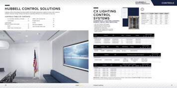
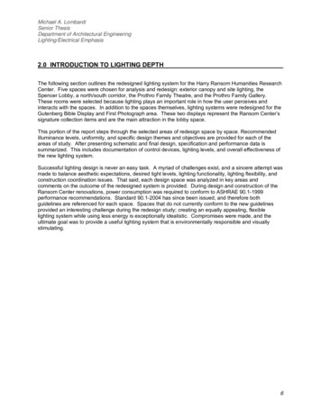
Application Note 107How dimmers work?Dimmers use various techniques to achieve the dimmingfunction.In this section, we will cover briefly how the various typesof dimmers available on the market operate.1. AC Phase cut dimmingAC phase cut is a dimming method where the dimmerchops part of the AC input voltage sine wave beforesending it to the driver and thus reduces the powerdelivered to the driver. The driver in turn produces anoutput current that is proportional to the reduced powerapplied by the dimmer. In other words, the light outputwill be proportional to the phase angle of the modifiedsine wave. This results in the dimming of the light output.Because Phase cut dimming occurs on the input AClines to the driver, this method is referred to as primaryside dimming, meaning that the dimming signal goes intothe primary side of the driver electronics. The phasedimmer is placed in series with the AC Line input asshown in figure 1 below while the 0-10V dimmers areconnected on the secondary side. ERP offers dimmerswith all three dimming options but we do not recommendusing more than one dimmer at the same time.internal circuit of the dimmer (fig. 2a) uses a TRIACdevice to chop the front end or leading edge of the ACsine wave as seen in fig 2b. The TRIAC-based dimmerconsists of a switch (the TRIAC) and a delay element (RCcircuit) that sets the time at which the TRIAC switch isturned on to allow the AC voltage to be applied to theload.Forward phase dimmers have been in use in the lightingindustry for decades. They are simple, low cost and easyto install. Because of that they have found widespreadacceptance in the industry. All it takes to install a forwardphase dimmer is for an electrician to remove a lightswitch and replace it with a dimmer/switch in the samejunction box with no additional wiring required.Figure 2a. TRIAC dimming circuit(Source LED Journal)Chopped AC Input to DriverAC Wall PowerFigure 2b. AC Forward phase TRIAC dimmingFigure 1. Block diagram with AC phase and 0-10Vdimming.Two types of AC phase cut dimmers are in use in theindustry.a)Forward Phase dimmersThe first is the Forward Phase dimmer also referred to asa TRIAC dimmer or a leading-edge dimmer because the-2-Figure 2c. TRIAC dimmer wiring diagram(source: LED Magazine)erp-power.com
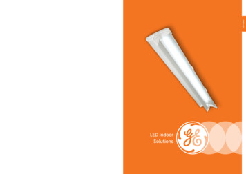
Application Note 107b) Reverse Phase dimmersThe second phase dimmer type is the Reverse Phasedimmer referred to as ELV or trailing-edge. ELV dimmers(Electronic Low Voltage) are much newer compared toTRIAC dimmers. They were initially developed to improvethe dimming performance of low voltage halogen lampswhen driven with Electronic Low Voltage transformers.ELV transformers, which are essentially switching powersupplies, replaced MLV (Magnetic Low Voltage)transformers in low voltage applications because of theirsmall size, low weight and good efficiency. However,when TRIAC dimmers were used with ELV transformerstheir performance was not optimum. For that reason, theELV dimmer was designed to offer better performancewith the capacitive nature of the ELV transformers.sine wave, and thus avoid fluctuation in the choppedsignal sent to the driver. Those fluctuations cause flickerin the LEDs.To achieve the above advantages, ELV dimmers have amore complex internal control circuit that drives a fastMOSFET switch element to generate precise AC voltagetrailing edge chopping.ELV dimmers have the disadvantage of being higherpriced and need to have additional wiring in the wall.They require the AC Neutral wire to be present in the wallelectrical box to connect to it (see figure 4). The Neutralconnection makes power always available to thedimmer’s internal circuitry regardless of how muchcurrent is drawn by the LED load.Unlike the forward phase case, the ELV dimmer cuts thetrailing edge of the AC sine wave as shown in Fig. 3.That is why Reverse phase dimmers are also referred toas Trailing-edge dimmers.Figure 4. ELV dimmer wiring diagram.(source: LED Magazine)Figure 3. AC Reverse phase ELV dimmingNote that cutting the leading edge of the sine wavecreates a sharp rise in the AC signal as seen in fig 2. Thissteep turn on causes high inrush currents whichgenerate EMI in switching power supplies, such as LEDdrivers, and put stress on the dimmers. Whereas in thereverse phase scheme the voltage cut off is on the backend of the sine wave which has no adverse effect on thedriver circuits. Here the turn on is slow with the slow riseof the sine wave, and that greatly reduces the inrushcurrent and therefore EMI. In fact, one of the reasons theELV dimmers were developed was to eliminate this highinrush problem when dimming low voltage halogenlamps that use ELV transformers, which as stated beforeare effectively switching power supplies. Anotheradvantage of ELV dimmers is their ability to consistentlydetect the zero-crossing point in the AC voltagewaveform ie to be fully synchronized with the input AC-3-Figure 5. TRIAC dimmer wiring diagram. (source: LEDMagazine)This is an improvement over TRIAC dimmers that areactually powered by the current flowing through themthat is drawn by the LED load (see figure 5). When theload pulls less current than the minimum TRIAC holdingcurrent (to be discussed in a later section), the TRIACdevice inside the dimmer turns off (misfires) andcompletely cuts the power to the LEDs. That misfiringcauses flicker in LED lights.erp-power.com
Application Note 1072. 0-10V Dimming3. DALI digital dimmingUnlike phase dimming, 0-10V analog dimming is asecondary side dimming scheme where the dimmingvoltage is applied on the secondary side of the driver(Figure 1) ie on the secondary side of the internaltransformer. 0-10V is a DC voltage standard that usestwo wires between the dimmer and the driver.The DALI standard (Digital Addressable LightingInterface) defined in IEC 62386 was initially released in2001. It is a digital protocol that enables the control oflighting fixtures in building automation applications via abus architecture where a controller addresses individualor groups of lights for control and status purposes. It isan open standard that has received widespreadacceptance in the lighting industry because of its manyadvantages. Devices that support the protocol arecompatible with other devices from differentmanufacturers and can be used interchangeably.This scheme has been in use for fluorescent andtheatrical applications for many years and has recentlyfound its way into LED lighting systems.It is a straight forward standard where the dimmerapplies a voltage between 0V and 10V to the driver. Thevoltage level is translated by the driver to a proportionaloutput current level, to drive the LEDs. Note that inpractice the driver provides the 10V signal to the dimmerand the dimmer reduces the voltage to dim the lights.Typically there is a linear relationship between theapplied voltage and the light output. At 10V the driveroutputs a current for full brightness, at 5V the output is athalf brightness and at 0V it outputs a current for thelowest brightness level.Other dimming profiles exist that are used with 0-10Vdimming where drivers implement a non-linear responsewith a dim-to-off function which allows the lights tocompletely turn off at the lowest dimmer setting. ERPdrivers offer linear and non-linear profiles with dim-to-offcapability. We will discuss this topic further at a latersection.Two types of 0-10V dimmers are available; sinkingdimmers and sourcing dimmers. These are defined bytwo standards bodies. The IEC defined the IEC 60929Annex E1-10Vstandard for general lighting. In thisstandard, the driver sources the current and the dimmersinks the current and the voltage varies from 10V formaximum light output to 1V for minimum output. Thesecond standard is the ESTA 0-10V standard defined fortheatrical applications, where the driver sinks the currentand the dimmer sources the current and where at 10Vthe lights are at the maximum output and at 0V they arecompletely off. The IEC 60929 Annex E standard forgeneral lighting is the more prevalent standard in themarket place.ERP drivers only support sinking dimmers where ourdrivers source the current to the dimmer. Currentsourced from the driver for sinking dimmers, is usually at1mA or less.-4-The DALI protocol defines a master/slave architecturewhere a controller/master sends command and addressinformation to lighting devices/slaves across a two-wireserial bus. Commands are decoded and acted upon bythe addressed lights. The DALI controller is also able torequest status from each of the lights to monitor thenetwork and make control decisions. This capabilitymakes DALI a bidirectional protocol. The DALI networkcan have up to 64 devices with a maximum length of300m.DALI offers many advantages over traditional dimmerslike simplified wiring and individually addressable lightingfixtures. These enable very flexible and powerful controlsof the lighting environment. For example, re-arranging alighting area and changing the dimming controlsbecomes as simple as moving a few icons on acomputer screen or selecting from pull down menus in aGUI.One of the most important advantages of the protocol, isdimming compatibility and consistency. Since dimminginformation is sent as digital commands, not analog likein the 0-10V scheme, all the lights will receive the samecommand and will execute in the exact same wayleading to a uniform dimming response.DALI is very popular in Europe and is gaining acceptancein the US.4. DMX512 digital dimmingDMX (Digital MultipleX) is also a digital communicationsstandard used to control theatrical and stage lighting. Itoffers the same advantages to lighting controls asdescribed in the DALI section above. DMX uses anarchitecture that is similar to DALI in that it is aMaster/Slave protocol with individually addressabledevices/lights, a two-wire serial bus (RS485 in this case)and bidirectional communication.erp-power.com
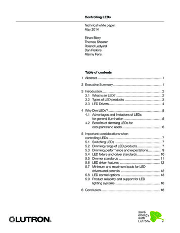
Application Note 107However, DMX offers much faster communications at250Kbps vs DALI’s 1200bps. The higher speed makes itpreferable for theatrical/stage application where there isa need for fast control of the lighting system such as fastcolor changing. The maximum practical bus length is300m which is similar to DALI.The standard supports 32 devices/lights but each of thedevices can be assigned several channels of theavailable 512 channels from the controller. A channel canbe thought of a communication channel to control aspecific function within a light like the dimming level. Thecontroller is connected to the light fixtures in a daisychain configuration.these dimmers are not capable of delivering the full 010V range to the drivers. When these dimmers are usedwith drivers that have a linear dimming curve the lightoutput at the low end does not dim very low and at thehigh end you will not get to full brightness. Drivers with alinear dimming curve, output a current that isproportional to the voltage it receives, across the full 010V scale as shown in figure 6.5. PWM dimmingPWM dimming is a digital dimming scheme that isimplemented by driving the LEDs with a square wavecurrent waveform. Unlike constant current reductionwhere the driver reduces the output current to dim thelights, the PWM signal waveform swings the LED currentfrom full on to off. By adjusting the duty cycle of thewaveform, ie the on time, the average current going intothe LEDs is changed which causes the lights to dim.PWM dimming has the advantage of not affecting thecolor or efficiency of the LEDs because the current levelis kept the same while only changing the duty cycle ofthe current signal (ie pulsing the current) to dim thelights.ERP drivers only support constant current reduction fordimming the light output.Figure 6. Linear dimming profile.Most customers expect 1% dimming from their lightingsystem but that can only be achieved when thedriver/dimmer pair is fully tested. ERP provides dimmingcompatibility lists with detailed test results to simplify theselection process. Table 1 below shows a typical ERP 010V dimmer compatibility table. Dimmers on this list areproven to produce good dimming performance with thedriver they were verified with.The PWM frequency needs to be high enough for theflicker not to be visible to the eye. A frequency at orhigher than double the line rate ie at greater than 120Hzin a 60Hz system, is recommended. According to sometests in the industry, at 200Hz there will be no noticeableflicker.0-10 V Dimming curves/profilesTable 1. 0-10V Dimmers compatibility listIn this section we will discuss four dimming profiles; theLinear profile, the Non-Linear profile, the Non-Linearprofile with dim-to-off and the logarithmic profile.1. Linear profile0-10V wall dimmers vary from manufacturer tomanufacturer and from model to model. In most cases-5-erp-power.com
Application Note 107Figure 8. Non-Linear dimming profile with Dim-to-offTable 2. Example Phase Dimmers compatibility list2. Non-Linear profileTo improve the dimming experience with dimmers thatare not able to provide the full 0-10V voltage range,newer drivers offer non-linear dimming curves where at acertain voltage on the low end of the range the driversets the light to 1% and at a certain voltage at the highend, the light is set to the maximum brightness of 100%as shown in figure 7.Figure 7. Non-LinearThe ANSI standards body is working on a standard thatwill define the thresholds and should simplify the task ofproviding a common response curve. The graph above(Fig. 6) shows a profile that closely resembles theproposed standard.4. Logarithmic profileThe Logarithmic profile (Fig 9) is another dimmingresponse that tries to emulate how the eye perceivesbrightness. In this case drivers will output a lower level oflight in the lower half of the dimming range because thehuman eye can perceive lower intensity light as a higherbrightness light. In the second half of the dimming scalethe light output will be increased faster as the dimmer ismoved towards the max position.dimming profile.3. Non-Linear with Dim-To-Off profileAnother non-linear dimming profile is offered where thelow and high thresholds are modified and the dim-to-offfunctionality is implemented as shown in figure 8. Dimto-off means the driver will turn the light off at or belowthe lowest threshold. In this case it is at 0.6V. ERP’sDraco family of drivers support the dim-to-off feature.-6-Figure 9. Logarithmic profile brightness vs dimmerposition.erp-power.com
Application Note 107Performance of LED lighting withlegacy phase dimmersAs described earlier, phase dimmers have severaladvantages like low cost and simplified installation.However, they have some disadvantages that lightingdesigners need to be aware of if they want to replacetraditional lighting technologies with LED lightingsuccessfully. We will address the most commonlimitations in this section.The problems encountered when using legacy dimmerswith LED lighting stem from the fact that these dimmerswere designed for incandescent and halogen lightswhich are resistive in nature. When using resistive loads,the current drawn from the dimmer is in phase and has alinear relationship with the voltage (Fig 10) whichgenerates smooth dimming.1. TRIAC Dimmer minimum load requirementWhen the current bursts die down, the driver stopsdrawing current from the dimmer. TRIAC phase dimmersrequire a minimum current, referred to as the holdingcurrent, to be drawn to keep them turned on. When theminimum current is not flowing through the TRIAC duringthe conduction period set by the dimmer, the TRIACcannot stay on (misfires) and that essentially turns theAC power off to the driver which leads to flicker andundesirable dimming performance.Although drivers nowadays use a PFC stage to smooththe current and make it linear and in phase with thevoltage, this issue is still present at very low currentstoward the end of the AC cycles.Because of that TRIAC dimmers specify that a minimumload be connected which is determined by the holdingcurrent requirement.To satisfy this requirement, LED drivers are designed todraw current from the phase dimmer even when the LEDlights are off. Also, newer dimmers have been designedto reduce their holding current requirement to a very lowlevel, therefore it is important to make sure a minimumload is connected to the dimmer.A better solution would be to use ELV dimmers that donot have a holding current requirement as they arealways powered from the mains by virtue of theirconnection to both the Line and Neutral wires. Ofcourse, ELV dimmers can only be used if a Neutral wireis available in the wall.Figure 10. Voltage and current relationship when drivinga resistive loadLED drivers on the other hand, are switch mode powersupplies that are capacitive. This means switchingdrivers draw current from the mains in bursts every cyclewhen charging their internal capacitors. In this case thecurrent waveform shows current spikes that have a nonlinear relationship with the input AC voltage as can beseen in figure 11.Figure 11. Voltage and current relationship when drivinga capacitive load-7-2. Inrush currentIn-rush current is generated by the drivers when firstpowered, and periodically during operation (referred toas repetitive peak current) on each rising edge of thechopped AC signal produced by forward phase dimmers(see figure 12). These currents can be as high as severalAmps. Inrush current is caused by the capacitive inputsof drivers and is governed by the following equation:i C dv/dtwhich states that the current is proportional to the rate ofchange of the voltage. When a fast-rising voltage isapplied, a large (inrush) current will flow. These highcurrents can cause damage to dimmers and othercomponents. Drivers are designed to have circuits thatlimit the in-rush current to meet the NEMA410requirement but they do not completely eliminate it. Alighting designer must insure that the dimmer used canhandle the total amount of in-rush current generated byerp-power.com
Application Note 107the LED loads attached to it. This is essentially a dimmermaximum load specification.In addition to the bad effects stated above, the sharprise in the voltage causes oscillation in the input EMIfilters of drivers. This translates to driver input currentoscillation that can move below and above the TRIACholding current which will force the TRAIC to turn off andback on repeatedly and that will result into light outputflicker.Flicker can be caused by many sources in a lightingsystem such as the driver output current ripple, linevoltage noise, dimmer operation (since it varies the ACline voltage), and the light source itself. In fact, differentLEDs have different characteristics that can cause somedrivers to perform well with some LEDs but not others.Output current ripple is the major contributor to flicker.Ripple is dependent on the driver topology. Early driverdesigns used single-stage power topology but newerdrivers are moving into two-stage which greatly reducesripple. The ERP Draco family of drivers are two-stagedrivers with current ripple at 10% or lower. This resultsinto a much-reduced flicker and enables fixtures to easilymeet or exceed the California Title 24 flicker specs.For best flicker performance with older single stagedrivers, it is advisable to only use dimmers fromcompatibility tables or conduct testing prior toinstallations.4. Dimming rangeA phase dimmer’s range is referred to as the conductionangle which is a measure of the time the dimmer isconducting within the 180-degree AC voltage sine wave.In figure 2 it is the range from the rising edge to the zerocrossing of the voltage waveform.Phase dimmers have different conduction angles withinthe 0-180 degrees span. When they are paired withdrivers that have a fixed dimming response ie fixedminimum and maximum settings, only a subset ofdimmers will perform well. The dimming performance willdepend on how well the dimmers’ range matches upwith that of the driver. That’s why it is important to testdrivers with many dimmers and come up with acompatibility list.Figure 12. Inrush and repetitive peak current withforward phase dimmers (Source Lutron)3. FlickerFlicker is the visible fluctuation of a light source. Alllighting technologies flicker when powered by thevarying AC line voltage. Flicker is present inincandescent as well as LED lights but it is less visiblewith incandescent lights because of the persistenceproperty of the filament ie when the power is turned offthe filament continues to glow for some time afterwards.LEDs on the other hand show flicker more easilybecause of their fast response to minor changes in thedrive current. That’s because LEDs are semiconductorsthat have a very fast response time in the nanosecondsrange.The ERP Draco family of drivers will be capable ofsupporting a programmable TRIAC dimming transferfunction to adapt to the various dimmer ranges on themarket.5. Low end dimmingOf particular importance in certain LED lightingapplications is the low end dimming level. In theseapplications the user requires the light output to be at avery low level when the dimmer is set at its lowestphysical position.This problem occurs when the dimmer range does notmatch the driver range as described in the previous-8-erp-power.com
Application Note 107section. Another issue experienced at the low end of thedimming scale is flicker. When the dimmer is set at itslowest position, very little power is delivered to thedriver. In this case the driver is not able to turn the LEDson and keep them on with the very low power available.This will cause the LEDs to flicker. To alleviate thisproblem, some dimmers have a manual trim adjustmentthat allows the user to raise the minimum dim level toprovide enough power to the driver to operate.6. CompatibilityEven though LED lighting needs to be compatible withphase dimmers there is no industry standard that definesdimmer characteristics. This causes compatibility issuesbetween the many dimmers on the market from differentmanufacturers and even from the same manufacturer,and LED lights.It is not uncommon to have a dimmer work well with anLED fixture and not be compatible with another.The best and easiest solution to this problem is toconduct dimmer/LED lamp pair testing and publishcompatibility lists for end users to refer to. ERP andother LED driver and dimmer manufacturers do makesuch lists available as shown in Tables 1 and 2 above.Performance of LED lighting with 010V dimmers0-10V dimmers tend to perform better than phasedimmers but they come at a cost. They require additionalwiring to be installed between the dimmer and thefixtures as opposed to phase dimmers. Although thisdimming method is simpler and offers betterperformance than phase dimming it does require carefulattention to a few things when installing such a system.1. Noise induced on wire runs0-10V DC wires are susceptible to noise pick up fromnearby AC power lines. The noise induced on the 0-10Vwires will affect the voltage levels and cause dimmingissues. To avoid this problem, it is advised not to bundle0-10V wires with AC wires in a conduit or run them nearAC lines. Careful attention needs to be paid to this verycommon mistake by installers.2. Wire length and multiple driversThe 0-10V dimming method uses DC voltage wires toconnect a dimmer to the drivers/fixtures beingcontrolled. Long wires can have voltage drop acrossthem which leads to different drivers receiving differentvoltages at their inputs. For example, the first driver inthe link (closest to the dimmer) will see a higher voltagethan the last driver (furthest away). This causesinconsistency of light output between fixtures as well asdimming range and accuracy issues. Although voltagedrop is minimal, installers that run into this issue canreduce the voltage drop along the wires by using lowergauge wires (thicker lower resistance) and/or by limitingthe length of the wires3. Dimmer rangeMany 0-10V dimmers have limited voltage range and arenot able to provide the full 0-10V voltage span to thedriver. Therefore, it is important to check dimmercompatibility lists to make sure that the right dimmer isused with a specific driver. In applications where the fulllight output range is desired, it is recommended that adriver with a non-linear dimming profile is used asdescribed in an earlier section.ConclusionThe conversion to LED lighting is expanding at a rapidrate due mostly to its low power consumption and longlife. When working with LED lighting where dimming inrequired it is important to understand the variousdimming options available, how they work and how theyperform in the real world. This app note was an attemptto offer the reader a full overview of the dimmingtechnologies available to lighting designers and installersand to highlight common issues that can arise in thefield.The information in this document is subject to change without notice. Other trademarks, product, and company names are the property of their respective owners and do not implyspecific product and/or vendor endorsement, sponsorship or association. This document is provided for informational purposes only and is not a warranty or a specification. Forproduct specifications, please see the data sheets available at www.erp-power.com. For warranty information, please contact ERP Sales at SaveEnergy@erp-power.com.U.S.A. HeadquartersTel: 1-805-517-1300893 Patriot Drive, Suite EMoorpark, CA 93021CHINA OperationsTel: 86-756-6266298No. 8 Pingdong Road 2 Zhuhai, Guangdong,China 519060-9-SaveEnergy@erp-power.comerp-power.com
that are designed specifically for LED lighting to improve the user experience. Other dimming methods exist such as the 0-10V analog dimming scheme. This scheme is widely used in the lighting industry in commercial applications where the 0-10V dimmer simply provides a low voltage DC signal to the l