Transcription
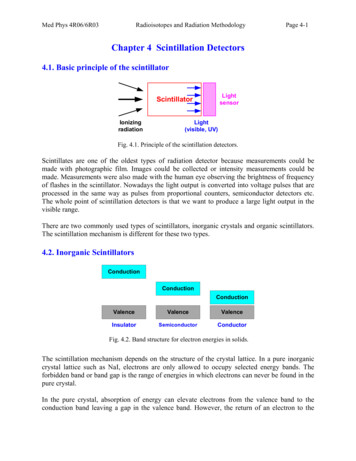
Med Phys 4R06/6R03Radioisotopes and Radiation MethodologyPage 4-1Chapter 4 Scintillation Detectors4.1. Basic principle of the onLight(visible, UV)Fig. 4.1. Principle of the scintillation detectors.Scintillates are one of the oldest types of radiation detector because measurements could bemade with photographic film. Images could be collected or intensity measurements could bemade. Measurements were also made with the human eye observing the brightness of frequencyof flashes in the scintillator. Nowadays the light output is converted into voltage pulses that areprocessed in the same way as pulses from proportional counters, semiconductor detectors etc.The whole point of scintillation detectors is that we want to produce a large light output in thevisible range.There are two commonly used types of scintillators, inorganic crystals and organic scintillators.The scintillation mechanism is different for these two types.4.2. Inorganic ValenceValenceInsulatorSemiconductorConductorFig. 4.2. Band structure for electron energies in solids.The scintillation mechanism depends on the structure of the crystal lattice. In a pure inorganiccrystal lattice such as NaI, electrons are only allowed to occupy selected energy bands. Theforbidden band or band gap is the range of energies in which electrons can never be found in thepure crystal.In the pure crystal, absorption of energy can elevate electrons from the valence band to theconduction band leaving a gap in the valence band. However, the return of an electron to the
Med Phys 4R06/6R03Radioisotopes and Radiation MethodologyPage 4-2valence band with the emission of a photon is an inefficient process. Few photons are releasedper decay, the energy is emitted by other mechanisms. In addition, band gap widths in purecrystals are such that the resulting emitted photon is too high to lie within the visible range.Small amounts of impurities are therefore added to the crystal. Tl is added to NaI in traceamounts. The impurities are called activators, they create special sites in the lattice at which theband gap structure, the energy structure, is modified. The energy structure of the overall crystalis not changed, just the energy structure at the activator sites.(a) Pure crystal(b) Activated crystalline scintillatorFig. 4.3. Energy band structure of an inorganic scintillator.At the few activator sites within the sample, the energy structure is modified. Energy states arecreated within what would be the forbidden band in the pure crystal. The electron can de-excitethrough these levels back to the valence band.The energy levels created by the activator’s presence within the crystal are narrower than in thepure crystal. The photons emitted by the transitions of electrons from upper to lower states will be lower inenergy than in the pure crystal: The emission spectrum is shifted to longer wavelengths and willnot be influenced by the optical absorption band of the bulk crystal. The photons are emitted in the visible range.Fig. 4.4. The emission spectra of several common scintillators.
Med Phys 4R06/6R03Radioisotopes and Radiation MethodologyPage 4-3A charged particle (e.g. a photoelectron) passing through the crystal will create a large numberof electron-hole pairs. The positive hole quickly drifts to the location of an activator site and the site is ionized. Theactivator sites are preferentially ionized because the ionization energy of the activator is lessthan a typical lattice site.The electron elevated to the conduction band is free to migrate through the crystal and willdo so until it encounters an ionized activation site.The electron drops into the impurity site, creates a neutral impurity configuration with itsown set of excited states.transition Excited configuration De-excitation occurs quickly with a high probability of photon emission.The activator is chosen so that the photon is visible.The typical half-life of the activator excited states are 10-7 seconds with the migration of theelectrons through the crystal taking a much shorter time. The timing of the light output istherefore dependent on the half-life of the state.ground stateTypes of inorganic scintillators:Alkali halide: NaI(Tl), CsI(Tl), CsI(Na), LiI(Ei)Other slow Inorganics: BGO, CdWO4, ZnS(Ag)Cerium-Activated Fast Inorganics: GSO, YAP, YAG, LSO, LuAP, LaBr3
Med Phys 4R06/6R03Radioisotopes and Radiation MethodologyPage 4-44.3. Organic ScintillatorsThe scintillation mechanism in organic materials is quite different from the mechanism ininorganic crystals. In inorganic scintillators, e.g. NaI, CsI the scintillation arises because of thestructure of the crystal lattice.The fluorescence mechanism in organic materials arises from transitions in the energy levels of asingle molecule and therefore the fluorescence can be observed independently of the physicalstate. For example anthracene is observed to fluoresce as a polycrystalline material a vapor part of a mixed solutionPractical organic scintillators are organic molecules which have symmetry properties associatedwith the electron structure.Fig. 4.5. Energy levels of organic molecules.Energy from a charged particle is absorbed and excites the electron into a variety of excitedstates - the singlet states (spin 0) are labeled S1, S2, S3 in Fig. 4.5. For organic scintillators thespacing between S0 and S1 is 3 to 4 eV, the spacing between the upper states is much smaller.Each of the S levels is subdivided into a series of levels with much finer structure (correspondingto the vibrational states of the molecule). The typical spacing is 0.15 eV. The 2nd subscriptdenotes the fine structure level.Spacing between S states is 3-4 eV, spacing in vibrational structure is 0.15 eVScintillation Mechanism
Med Phys 4R06/6R03Radioisotopes and Radiation MethodologyPage 4-5 At room temperature, average energy is approximately 0.025 eV so all molecules are in theS00 state. When the charged particle passes through, kinetic energy is absorbed by the molecules, andelectrons are excited to the upper levels. The higher states S2, S3, de-excite quickly (picoseconds) to S1 state through radiationlesstransitions (internal conversion). States such as S11, S12 that have extra vibrational energy and are not in thermal equilibriumwith neighboring molecules, quickly lose energy. After negligibly short time a population of excited molecules in S10 state is produced as thenet effect of the excitation process.Scintillation light, prompt fluorescence, is emitted in transitions between S10 and the ground state.The prompt fluorescence intensity at time t following excitation is described byI I0e-t/τwhere τ is the fluorescence decay time for the S10 level.In most organic scintillators, τ is the order of a few nanoseconds therefore organic scintillatorsare fast.The lifetime for the T1 state is much longer than the S1 state. T1 is populated by a transitioncalled an intersystem crossing. The lifetime of the T1 state can be ms.T1 S0 transitions give rise to phosphorescence (delayed light emission).T1 lies below S0, therefore the wavelength of the emitted phosphorescence is longer than thewavelength of the fluorescent light. The phosphorescent light can be discriminated from thescintillation light on the basis of timing and wavelength.The energy level scheme explains why organic scintillators can be transparent to their ownfluorescence emission. All fluorescence emissions (except S10 S00) have a lower energythan the minimum required for absorption. There is little overlap between emission andabsorption spectra, therefore the emitted light mostly passes straight on through the scintillationmedium.Types of organic scintillators:Pure organic crystals: Anthracene, StilbeneLiquid organic solutions: by dissolving an organic scintillator in a solventPlastic scintillators: dissolving & polymerizing4.4. Photomultiplier Tubes (PMT) and Photodiodes
Med Phys 4R06/6R03Radioisotopes and Radiation MethodologyPage 4-6In order to provide a useful measurement device, an electrical signal has to be formed from thescintillation light. Two main types of device are used to do this; the photomultiplier tube and thephotodiode.A. Photomultiplier Tube (PMT)Photomultiplier tubes are extremely good atconverting light into an electrical signal; electricalpulses can be obtained from a few hundred visiblephotons.PhotocathodePhotomultiplier tubes are vacuum tubes in which thefirst major component is a photocathode. A lightphoton may interact in the photocathode to eject alow-energy electron into the vacuum. This process canbe thought to occur in three steps1) absorption of the photon and energy transfer to theelectron in the photocathode material2) the migration of the photoelectron to the surface ofthe photocathode3) escape of the electron from the photocathodesurface.Fig. 4.6. Basic elements of a PMT.The energy available to be transferred from a scintillation photon to an electron is, for bluescintillation light, approximately 3 eV. However, some of this energy is lost in electron-electroncollisions as the electron migrates to the surface and then the potential barrier at the surfacevacuum interface (the work function) must be overcome in order for the electron to enter thevacuum. There are therefore energy limitations on the system posed by the potential barrier atthe surface/vacuum interface and the interactions in the material.Some limitations are placed on the materials that can be used for the photocathode. Typicallymetals have a work function of 3 4 eV, semiconductors 1.5 2 eV.In addition, the thickness of the material that can generate photoelectrons into the vacuum islimited, because there is a rate of energy loss as the electron migrates to the surface. For metalsthis energy loss rate is relatively high and an electron will have its energy drop below thepotential barrier after traveling only a few nanometers. In semiconductors the electron can travel20 – 30 nanometers, before its energy drops below the barrier. In either case only a thin layer ofmaterial contributes photoelectrons into the vacuum. The cathodes are sometimes designed sothat the light is incident on one side, while the electrons are ejected on the other. Thephotocathode is therefore extremely thin, because of the problems of electron interaction in thematerial, and is therefore semi-transparent to visible light. This means that a large proportion(more than half) of the light passes straight through without interacting with the photocathode.
Med Phys 4R06/6R03Radioisotopes and Radiation MethodologyPage 4-7Even if the work function is low, the necessary thinness of the photocathode means that they canonly convert, at best, a small proportion of the photons.The problems of work function and electron interactions in the material mean, in addition, thatall photocathodes have an energy cut-off with respect to the frequency of the light that cangenerate photoelectrons into the vacuum. Some light frequencies cannot create electrons withenough energy to overcome the potential barrier. The energy cut-off is usually in the infra-red ornear infra-red part of the spectrum.The sensitivity of a photocathode is usually quoted in terms of the quantum efficiency. Thequantum efficiency of the photocathode is defined as the probability for the conversion of lightto an electrical signal and is defined asQuantum efficiency number of photoelectrons emitted/ number of incident photonsThe quantum efficiency is a strong function of wavelength of the incident light, and an effort ismade to match the spectral response of the photocathode to the emission spectrum of thescintillator in use. The average quantum efficiency over the emission spectrum of a typicalscintillator is about 15 to 20 percent while the peak quantum efficiency is 25 30 %. Thestandard for quotation is the number of photoelectrons per keV energy loss by fast electrons in aNaI(Tl) crystal. For the peak quantum efficiency, about 8 10 photoelectrons are produced perkeV energy loss. Therefore, the average energy loss required to create a single photoelectron (orone basic information carrier) is 100 eV, which is much bigger than the values in gas-filled orsemiconductor detectors. Presently, multialkali (based on Na2KSb) and bialkali (based onK2CsSb) materials are usually used for the photocathode.Fig. 4.7. The spectral sensitivities of photocathode materials.Electron Multiplication
Med Phys 4R06/6R03Radioisotopes and Radiation MethodologyPage 4-8A PMT takes the electrical signal from the photocathode and amplifies through a dynode chainby the process of electron multiplication.Electrons are ejected from the photocathode into the vacuum with an energy of 1 eV and areaccelerated by a voltage of a few hundred volts toward an electrode. The accelerated electron hasan energy of a few hundred electron volts upon arrival at the electrode; this deposition of kineticenergy can result in the re-emission of secondary electrons. It typically takes 2-3 eV to excite anelectron in the dynode, so 100 V can theoretically create 30 electrons.However, there is the same problem as in the photocathode; electrons must be near the surface tobe emitted, otherwise they lose too much energy through collisions and are unable to overcomethe potential barrier at the surface. Only a small proportion of the electrons excited up to theconduction band reaches the surface and creates secondary electrons.The overall multiplication factor for a single dynode is given byδ number of secondary electrons emitted / primary incident electronδ is typically 4 6 for voltages of a few hundred volts.Multiple Stage MultiplicationPhotomultiplier tubes employ dynode chains of several stages of multiplication to create electrongains of the order of 106.Electrons are created in the photocathode, and accelerated toward the first dyode, wheresecondary electrons are emitted. The secondary electrons are accelerated by the electric fieldtoward a second dynode, where they create secondary electrons, and so on. This can be repeatedmany times.NThe overall gain for the PM tube αδWhere N is the number of multiplication stages, α is the fraction of electrons collected by themultiplier structure, and δ is the multiplication factor for a single electrode.For typical tubes δ is around 5 and α approaches unity. 10 stages of multiplication result in an107overall tube gain of 5 or 10 .Statistics of Electron MultiplicationThe emission of secondary electrons from the dynodes is a statistical process, so themultiplication factor δ is not a fixed constant but varies from event to event around a meanvalue. Therefore pulses are amplified overall down the dynode chain by a mean value which hassome statistical variation.
Med Phys 4R06/6R03Radioisotopes and Radiation MethodologyPage 4-9We measure a final mean voltage that has statistical spread, i.e. we measure not just a singleenergy, but a mean energy with a spread. The dynode chain therefore affects the energyresolution of the system.We can assume a simple model where the production of secondary electrons follows a Poissondistribution about an average yield.A single photoelectron incident on the first dynode results in a mean number of secondaryelectrons of δ δ. The relative variance is thus 1/δ.The process is compounded over N identical stages of the PM tube, and the mean number ofNelectrons collected at the anode is given by δ .23NThe relative variance in this number is 1/δ 1/δ 1/δ 1/δ 1/(δ-1)The variance in the dynode chain adds to the poor observed energy resolution of scintillationdetectors.Fig. 4.8. Different configurations of PMTs.B. PhotodiodesAn alternative way to detect the scintillation light is the use of a silicon photodiode. This is asemiconductor device which consists of a thin layer of silicon in which the light is absorbed afterwhich free charge carriers (electrons and holes) are created. Electron and holes are collected atthe anode and cathode of the diode. Most frequently used are PIN diodes operated in reverse biasmode.Photodiodes have potential advantages: higher quantum efficiency and compact size. However,electronic noise is a major problem due to the small signal amplitude.
Med Phys 4R06/6R03Radioisotopes and Radiation MethodologyPage 4-10References1. G.F. Knoll, Radiation Detection and Measurement - 3rd edition (Chapters 16 to 18), John Wiley & Sons,1999.
Alkali halide: NaI(Tl), CsI(Tl), CsI(Na), LiI(Ei) Other slow Inorganics: BGO, CdWO4, ZnS(Ag) Cerium-Activated Fast Inorganics: GSO, YAP, YAG, LSO, LuAP, LaBr3. Med Phys 4R06/6R03 Radioisotopes and Radiation Methodology Page 4-4 4.3. Organic Scintillators The scintillation mechanism in organ