Transcription
Downloaded from jnm.snmjournals.org by on February 8, 2016. For personal use only.Scintillation Crystals for PET*Charles L. MelcherCT! Inc., Knoxville, Tennesseecrystal,a fractionof the energylocalizeson the activatorIn PET, inorganic scintillator crystals are used to record -y-raysproduced by the annihilation of positrons emitted by injectedtracers. The ultimate performanceof the camera is strongly tiedto boththe physicaland scintillationpropertiesofthe crystals.Forthis reason, researchers have investigated virtually all knownscintillatorcrystals for possibleuse in PET.Despitethis massiveresearcheffort, only a few differentscintillatorshave been foundthat have a suitable combination of characteristics,and only 2(thallium-doped sodium iodide and bismuth germanate) havefound widespread use. A recently developed scintillator crystal,cenum-doped lutetium oxyorthosilicate,appears to surpass allpreviously used materials in most respects and promises to bethe basisfor the next generationof PETcameras.KeyWords: J NucI Med 2000;41:1051â ”1055ions. Relaxation of the activatorionsresultsin the emissionof scintillation photons, typically around 4 eV, corresponding to visible blue light.In the early years of PET, detectors were made of singlecrystals ofthallium-dopedsodium iodide (NaI[Tl]),individually coupledto photomultiplier tubes(PMTs).With thediscoveryof bismuth germanate(Bi@Ge@O12or BGO), most detectordesigners converted to this material because of its much greaterefficiency for detecting â y-rays.Ablock detectorbecame the mostwidely useddesign,in which a BGO block is segmentedinto asmany as 64 elements and coupled to 4 PMTs (1). Otherscintillators have included barium fluoride (BaF2 [2]), yttriumaluminate (YA1O3[Ce]or YAP) (3), and cerium-dopedgadolinmm oxyorthosilicate(Gd2SiO5[Ce]or GSO) (4). In recentyears,a promisingnew material, cerium-dopedlutetium oxyorthosilicate (Lu25i05[Ce] or LSO) (5), has emerged and is likelyto be used widely in future generation PET scanners.scintillator is a material with the ability to absorbionizing radiation, such as x- or rny-rays,and to convert afraction of the absorbed energy into visible or ultravioletphotons. The conversion process typically takes place on atime scale of nanoseconds to microseconds, thus producinga brief pulse of photons corresponding to each rnl'-or x-raythat interacts with the scintillator material. The light pulse,the intensity of which is usually proportionalto the energydeposited in the scintillator, is sensedby a photodetector andconverted into an electrical signal.Scintillators may be liquid or solid, organic or inorganic,and crystalline or noncrystalline. Organic liquid and plasticscintillatorsoften are usedfor detectionof @3particles andfast neutrons. For the detection of x- and -y-rays, such as the511 keV -1'-raysused in PET, inorganic single-crystal scintillators are used, becauseof their generally higher density andatomic number, which lead to better detection efficiency.A typical scintillator is a transparent single crystal inwhich valence and conduction bands are separated by a bandgap of 5 eV or more. In a perfect crystal, free of defects orimpurities, there would be no electronic energy levels in thisgap. However, most scintillators are doped with an activatorion that provides energy levels in the otherwise forbiddenband gap. After absorption of â y-rayenergy by the bulkReceivedJan. 7, 2000; revisionaccepted Feb. 9, 2000.Forcorrespondenceor reprintscontact:CharlesL Melcher,PhD, CTI, Inc.,810 InnovationDr.,Knoxville,TN37932.*NOTE: FOR CE CREDIT, YOU CAN ACCESS THIS ARTICLE ON .THE SCINTiLLATION PROCESSThe process whereby a scintillator converts the energydeposited in it by a â y-rayinto a pulse of visible (or ultraviolet[UV}) photons includes 3 main steps. According to Lempicki et al. (6), the overall efficiency (â ri)of the conversionprocess may be characterizedas the product of 3 factors:â vi I3SQ,where 1@is the conversion efficiency of the â y-rayenergy toelectron hole pairs, S is the transfer efficiency of the energyheld by the electron-hole pairs to the activator ions or otherluminescence centers, and Q is the quantum efficiency of theluminescence centers themselves.Robbins (7) demonstrated that @3can be calculated fromthefundamentalphysicalpropertiesof thescintillatorcrystal, including the electronic band gap, the high-frequencyand static dielectric constants,and the optic longitudinalphotonenergy.For many scintillatormaterials,theseparameters are well known; consequently, the conversion efficiency can be calculated with reasonable confidence. Forsome newer scintillators,however, some of the parametersare not known precisely, thus resulting in a significantuncertaintyin the calculatedconversionefficiency.Despite the obvious importance of 5, no model exists tocalculateit reliably. In fact, perhapsthe primary challengeofcurrent scintillator research is to develop an accurate modelof this crucial process.SCINTILLATIONCRYSTALSFORPETâ Melcher1051
Downloaded from jnm.snmjournals.org by on February 8, 2016. For personal use TABLE 2Physical Properties of Some Common Scintillator Crystalslight, the energy of which matches the excitation energy ofthe center. In this way, the electron-hole creation step and theenergy transfer step are bypassed, and the efficiency of theluminescence center itself can be observed directly.EffectiveCrystalDensityCHARACTERISTiCS OF ThE IDEAL oYesBi4Ge3O12(BGO)7.1375NoYesGd2SThe ideal scintillator would have a combination of severalphysical and scintillation properties (Table 1). A highdetection efficiency for the -y-rays of interest requires bothhigh atomic number for a large photoelectron cross sectionand high density for a large Compton-scatteringcrosssection. These are the 2 main interactions through which 511keV rny-raysinteract with the scintillator crystals. For goodcoincidence timing and high count-rate capability, a shortdecay constant is required. In other words, the pulse ofscintillation photons must be as brief as possible. A highlight output allows a large number of crystal elements to becoupled to a single photodetector, and good energy resolution allows a clear identification of full energy events. Thetransmission ofthe scintillation light pulses into the photodetector is best when the refractive index of the scintiulatormaterial is similar to that of the entrance window andcoupling material, usually near 1.5. In some materials, colorcenters may be easily produced by ionizing radiation, thusimpeding the transmission of the scintillation light throughthe scintillator itself. Therefore, a resistance to this effect,known as radiation hardness, is desirable. Some scintillatorsare hygroscopic, i.e., they readily absorb water from theatmosphere and therefore require special packaging tohermetically seal them. Nonhygroscopic materials have anadvantage, in that simpler packaging may be used. Mechanical ruggedness is desirable, because it makes fabrication ofsmall crystals easier. Because a PET scanner may useTABLE 1Properties of the Ideal Scintillation Crystal for onwavelengthnear400 nmTransparentat emissionwavelengthIndexof nefficiencyHigh -y-ray detection efficiencyGoodcoincidencetimingAllowslargenumberof of fullenergyeventsGoodmatchto photomultipliertuberesponseAllowslightto travelunimpededto photomultipliertubeGoodtransmissionof lightfromcrystalto iespackagingAllowsfabricationof Ye817NoNo5,000â ”10,000cc of scintillator crystals, the growth of largevolumes of crystals at a reasonable cost must be feasible.PROPERTIES OF COMMERCIAL SCINTILLATORSBecause the ideal scintillator does not actually exist, onemust look at the characteristics of materials that do exist andchoose the one best suited to the application. Table 2 showsthe physical properties of some commonly available scintillator materials, listed in order of decreasing density. BothBGO and LSO have excellent physical properties. Theyhave high density and atomic number that result in efficientdetection of â y-raysand are also rugged and nonhygroscopic,which allows relatively simple detector fabrication. Cadmium tungstate and GSO are also good candidates, exceptthat both cleave easily, which makes detector fabricationmore difficult.Table 3 shows the scintillation and optical properties ofsome common scintillators, listed in order of increasingdecay constant. BaF2 has the shortest decay constant by far:0.8 ns. Unfortunately, the emission is weak and located inthe far UV at 220 nm, which requires PMTs with moreexpensive quartz windows. It also has a long secondarycomponent of 600 ns. Cesium fluoride (CsF) has a very shortdecay constant of 4 ns, but its intensity is so weak that thisscintillator is seldom used. LSO has the best combination ofa short decay constant, 40 ns, and high emission intensity. Inaddition, it has no secondary decay component.SCINTILLATORSUSEDIN PETNaI(Tl) was discovered in 1948 by Hofstadter (8). Itquickly became the scintillator of choice for radiationdetection because of its high light output, i.e., efficientconversion of deposited -y-ray energy to scintillation photons. The large light pulses are easily processed by conventional pulse-shaping electronics. The main disadvantage ofNaI(Tl) is its low detection efficiency for â y-raysabove 200keV, as a result of low density and moderately low atomicTi@JouRNALOFNUCLEARMEDICINEâ Vol. 41 â No. 6 â June2000
Downloaded from jnm.snmjournals.org by on February 8, 2016. For personal use only.TABLE 3Scintillation and Optical Properties of Some Common Scintillator ssion SO)60600304301.85Nal(Tl)230â 1.80CdWO45000â ”20,000204802.20number. At the energies typically used in SPECT (140 keV),the detection efficiency of NaI(Tl) is satisfactory, and it isused almost exclusively in that application. However, forhigher energy applications, such as PET (511 keY), NaI('fl)has been replaced, for the most part, by materials with higherdensity and atomic number. An additional disadvantage ofNaI(Tl)is that it is highly hygroscopic.As a result, a greatdeal of effort has gone into the development of hermeticpackaging to protect the material from moisture in theatmosphere.BGO emerged in the early 1970s, with initial studiesreported by Weber and Monchamp (9). Although the lightoutput of BOO is only about 15% of that of NaI(Tl), itsdramatically higher detection efficiency, as a result ofdensity almost twice that of Nal as well as a much higheratomic number, has made it a very popular choice for thedetection of radiation above a few hundred keV. PET is themajor ongoing application of BGO crystals today, despitethe fact that their relatively long decay constant of 300 nslimits coincidence timing resolution.Scintillators with extremely short decay constants offerthe possibility of time-of-flight PET, in which opposingdetectors measure the difference in the arrival times of a pairof y rays. In this way, the location of the positron event canbe localized along the line connecting the 2 detectors. Twopossibilities that appear in Table 3 are CsF and BaF2. CsFhas very low light output and is very hygroscopic and,crystalscleaveeasily.Thus, specialtechniquesare neededtoavoid cracking the crystal elements during cutting.LSO offers the best combination of properties for PET ofany scintillator known today (13). It has high density andhigh atomic number for good -y-ray detection efficiency, ashort decay constant for good coincidence timing, and highlight output that allows the use of many small elements perPMT. In addition, it is mechanically rugged and nonhygroscopic,thusallowing relatively simple fabricationof detectors. LSO has a low level of natural radioactivity as a resultof the presence of â 76Lu,but the counting rate from thisisotope is a small fraction of the typical counting rates fromthe injected tracers; thus, it is not a significant problem forPET. LSO hasbeenusedin a high-resolutionbraintomograph (14), high-resolution animal tomographs (15), combinedPETIMRIdetectors(16), andcombinedPET/SPECTcameras (17). Large-scale commercial production of LSOhas been realized during 1999 (18), and widespread use ofthis scintillator is expected in the future.PROPERTIESOF SCINTILLATORSFOR PETDespite the investigation of virtually every known scintillator for possible use in PET, only 2 have seen widespreaduse so far, NaI(Tl) and BOO. A third, LSO(Ce), is expectedto see widespread use in the future. In this section, theproperties of these 3 important scintillators are compared inmore detail.One of the most important properties of a scintillator forconsequently,has seenlittle use despiteits shortdecayconstant of 4 ns. BaF2has an even faster decay of less than 1 PET is y-raydetectionefficiency.Becauseof thedesiretons, greater light output, and is nonhygroscopic.Therefore, inshorten scan times and maintain low tracer activity, thethe early 1980s it was used in several PET scanners (10). crystals must detect as many of the -y-rays emitted asHowever, because of its relatively low density and atomic possible. This is the primary reason for the popularity ofnumber, it eventually gave way to BGO.BGO. â y-rayswith energy of 511 keV interact with solidOne way to increase the spatial resolution of a tomograph matter primarily through 2 phenomena, the swithdifferentdecay effect and the Compton effect. In the photoelectric effect, theconstants to a single photodetector. Pulse-shape discrimina-y-ray is absorbed by an atom that ejects an electrontion is used to identify the crystal element of interaction.(photoelectron) and also produces either characteristicGSO has been used in conjunction with BOO in this way for x-rays or Auger electrons. The end result is that the fullenergy of the â y-rayis absorbed. In Compton scattering, thea high-resolution tomograph (4,11). A tomographic designusingGSOexclusivelyhasalsobeenreported(12). Fabrica -y-ray loses a fraction of its energy to an electron throughtion of GSO detectors requires great care, because the scattering. The energy of the electron is likely to be absorbedSCINTILLATIONCRYSTALSFORPETâ Melcher1053
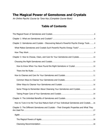
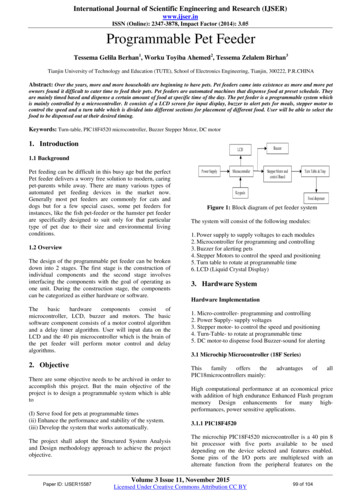
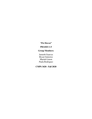
Downloaded from jnm.snmjournals.org by on February 8, 2016. For personal use only.in the crystal, whereas the scattered -y-ray may or may not beabsorbed. The distribution of energy between the electronand the â y-rayis determined by the scattering angle.The detection efficiency of a detector may be characterized by the fraction of incident -y-rays that are partially orfully absorbed by it. For a detector of thickness x, exposed toa mono-energetic beam of rny-rays,the initial y-ray intensity,I@,is attenuated according to:1(E) I0(E) exp (â ”six),where I is the intensity of -y-rays passing through thedetector without interacting at all, and pi is the linearattenuation coefficient. The y-rays that do interact in thedetector by depositing either their full or partial energy aregivenby:A 1 â ”exp(â ”px).Thus, it is clear that the fraction of incident rny-raysthat arepartially or fully absorbed is determined by the linearattenuation coefficient (for an idealized geometry). Figure 1compares the linear attenuation coefficients for Nal, BOO,and LSO. From these data, the advantagesof BOO and LSOover Nal are clear. At 511 keV, p 0.96 cm â for BOO and1.1 0.87forLSO,whereasforNal,p is only0.35cm*Consequently, to achieve similar efficiency, Na! detectorsmust be more than twice as thick compared with BOO andLSO detectors.In most PET scanners, the emission of the scintillationcrystals is converted to electrical signals by PMTs. Toproduce the largest signal, the scintillation emission shouldbe as intense as possible, and the wavelength of the emissionshould match the wavelength of maximum photomultipliersensitivity. Because bi-alkali photomultipliers with glassentrance windows, the most commonly used type, have amaximum sensitivity near 400 nm, it is advantageous for thescintillator to have its emission maximum near this wavelength. Both Nal and LSO have intense emissions that peakFIGURE2. Scintillationemissionspectraof Nal(TI),BOO,andLSO(Ce),under-y-rayexcitation.near that wavelength, whereas BOO has a much weaker andlonger wavelength emission (480 nm) (Fig. 2). The intensityof the scintillation emission strongly affects the number ofcrystal elements that can be coupled to a single PMT or,stated another way, the ratio of scintillation elements toelectronic channels. With BOO, block detectors today use upto 16 crystal elements per PMT, whereas LSO detectors useup to 144 crystal elements per PMT. Thus, LSO makespossible significant cost savings as a result of the reducednumber of photomultipliers.In PET, the decay constant of the scintillation emission isvery important, because singles count rates are typicallyvery high, and coincidence resolving time should be as smallas possible to reject unwanted random events. A shortscintillation decay constant is a benefit in both instances.Figure 3 compares the scintillation decay of NaI(Tl), BOO,and LSO. BOO has the longest decay, 300 ns. The primarydecay constant of NaI(Tl) is somewhat shorter, 230 ns, )FIGURE 1. Total linear attenuation coefficients of Nal, BGO,and LSO.1054@ooTime(nil20003000FIGURE3. Decayofthe scintillationemissionof NaI(TI),BOO,and LSO(Ce),after excitationby -y-rays.Ti@ Jou@.r@i OF NUCLEARMEDICINE â Vol. 41 â No. 6 â June 2000
Downloaded from jnm.snmjournals.org by on February 8, 2016. For personal use only.an additional secondary decay of several microseconds isalso present. The decay constant of LSO is several timesshorter, 40 ns, and no secondary component is present.Because the quality of a PET image is strongly dependenton the coincidence resolving time of the detectors, a figureof merit that has been used for PET scintillators is thenumber of photons emitted per nanosecond. In this way,both the overall intensity of the emission as well as theduration of the pulse are accounted for in 1 parameter.Figure 4 compares the photons emitted per nanosecond forNal, BOO, and LSO. LSO has a large advantage over BOOin this respect, because LSO's emission is both intense andfast, whereas BOO's emission is much weaker and slower.LSO is also better than Nal in this respect, becausealthoughNal's emission is stronger than LSO, the decay constant ismore than 5 times longer.FUTURE RESEARCH DIRECTIONSResearchers continue to actively investigate potential newscintillator materials, because a tomograph's performancedepends so strongly on the characteristics of the detectors.Most of the effort has focused on high-density and highatomic-number materials as well as materials with potentially very short decay constants. Surveys of large numbersof candidates (19) have failed to identify any practicalscintillators for PET. Recent research, therefore, has shiftedtoward computational efforts to model potential materials(20,21). Hopefully, an improved understanding of the underlying physics of scintillation processeswill lead to theability to predict the characteristics of new scintillatormaterials without actually synthesizing them.In addition to searching for new scintillator materials,investigators have combined known scintillators in novelways, such as phoswich detectors, which combine 2 dissimilar scintillators in the same detector. For instance, layers ofLSO and NaI(Tl) have been combined to make a camera thatprovides both PET and SPECT capability (18). The LSOlayer is used for PET imaging and the NaI(Tl) layer is usedfor SPECT imaging. Similarly, researchershave constructedprototype detectors of LSO and YSO for the same purpose(22).ACKNOWLEDGMENTSThe author is grateful to Lars Eriksson and Mike Caseyfor several useful discussions.REFERENCES1. Casey ME, Nutt R. A multi-crystal two-dimensional BOO detector system forpositron emission tomography. IEEE TransNuclSci. 1985;NS33:460-463.2. TI:Apositronemission tomograph utilizing photon time-of-ffight information. IEEE Trans MedImaging. 1982;M1-1 :179â ”I87.3. Weber 5, Bauer A, Herzog H, et al. Recent results of the TierPET scanner. In:Seibert JA, ed. 1999 IEEE Nuclear Science Symposium and Medical ImagingConftrence Record. Piscataway, NJ: Institute of Electrical and ElectronicsEngineers, Inc.; 2000.4. Karp J, Adam L-E, Freifelder R, Muchilebner G, Liu F, Surti S. High resolutionGSO-based brain PET camera. In: Seibert JA, ed. 1999 IEEE Nuclear ScienceSymposium and Medicallmaging Conference Record. Piscataway, NJ: Institute ofElectrical and Electronics Engineers, Inc.; 2000.5. Melcher CL, SchweitzerJS.A promisingnew scintillator@cerium-dopedlutetiumoxyorthosilicate. NucI InsirMeth. l992;A3 14:212â ”214.6. Lempicki A, Wojtowicz AJ, Berman E. Fundamentallimits of scintillatorperformance. NucI lnstr Meth. 1993;A333:304â ”311.7. Robbins Di. On predicting the maximum efficiency of phosphor systems excitedby ionizing radiation. JElectrochem Soc. 1980;127:2694â ”2699.8. Hofstadter R. Alkali halide scintillation counters. Phys Rev. l948;74:lOOâ ”lOl.9. Weber MJ, MonchampRR. Luminescenceof Bi@Ge3O12:spectraland decayproperties. JAppl Phys. 1973;44:5495â ”5499.10. YamamotoM, FIckeDC,Ter-PogossianMM.Experimentalassessmentof the11.12.13.14.15.16.17.gain achieved by the utilization of time-of-ifight information in a positron emission tomograph(superPElT I). IEEE TransMedlmaging. 1982M1-1:187â ”192.Eriksson L, Bohm C, Kesselberg M, Liuon J-E, Bergstrom M, Blomquist GA. Ahigh resolution positron camera. In: Greitz T, Ingvar DH, Widen L, eds. TheMetabolism of the Human Brain Studied with Positron Emission Tomography.New York, NY: Raven Press;1985:33â ”46.Holte 5, Ostertag H, Kesselberg M. A preliminaiy evaluation of a dual ctystalpositron camera. J ComputAssist Tomogr. 1987;Il:691â ”697.Melcher CL, Schweitzer JS. Cerium-doped lutetium oxyorthosilicate: a fast,efficient new scintillator. IEEE Trans NuclSci. 1992;NS39:502â ”505.Schmand M, Eriksson L Casey ME, et al. Performance results of a new DO!detector block for a high resolution PET-LSO research tomograph HRRT. iEEETrans NuclSci. 1998;NS145:3000-.3006.Chatziioannou AF, Cherry SR. Shao Y, et al. Performance evaluation ofmicroPET: A high resolution LSO PET scanner for animal imaging. J NucI M&L1999;40:1164â ”1175.Shao Y, cheny SR. Famiiani l( et al Development of a PEI@detector systemcompatible with MRJ/NMR systems. IEEE Trans NuclScL 1997NS44: 1167-1171.Schmand M, Dahibom M, Eriksson L, et al. Performance of a LSO/NaI(11)phoswich detector for a combined PET/SPECT imaging system. I Nuc! Med.1998;39(suppl):9P.18. Melcher CL, Schmand M, Eriksson M, Ct al. Scintillation properties of LSO:Ceboules.In: SudharsananR, ed. 1998IEEE NuclearScienceSymposiumandMedical Imaging Conference Record. Piscataway, NJ: Institute of Electrical andElectronics Engineers, Inc.; 1999.19. DerenzoSE,MosesWW,CahoonJL. Prospectsfor newinorganicscintillators.1@@uec)FIGURE 4. Comparisonof rate of scintillationemission(photons emitted per nanosecondafter excitation)for NaI(Tl), BOO,and LSO(Ce).IEEE Trans Nucl Sci. l990;NS37; 203â ”208.20. Andriessen J, Dorenbos P. van Eijk CWE. Calculation ofenergy levels of ceriumin inorganic scintillator crystals. In: Weber MJ, Lecoq P, Ruchti RC, Woody C,Yen WM, Thu R, eds. Scintillator and Phosphor Materials. Pittsburgh, PA:Materials Research Society; 1995:355â ”365.21. Derenzo SE, Klintenberg M, Weber Mi. Ab-initio cluster calculations of holeformation and trapping in PbF2 and PbF4. In: Sudharsanan R, ed. 1998 IEEENuclear Science Symposium and Medical Imaging Conftrence Record. Piscataway, NJ: Institute ofElecuical and Electronics Engineers, Inc.; 1999.22. Dahlbom M, MacDonald 13., Schmand M, et al. A YSO/LSO phoswich arraydetector for single and coincidence photon imaging. iEEE Trans NucI Sci.1998;NS45:1128â ”1132.SCINTILLATIONCRYSTALSFORPETâ Melcher1055
Downloaded from jnm.snmjournals.org by on February 8, 2016. For personal use only.Scintillation Crystals for PETCharles L. MelcherJ Nucl Med. 2000;41:1051-1055.This article and updated information are available ormation about reproducing figures, tables, or other portions of this article can be found online .xhtmlInformation about subscriptions to JNM can be found nline.xhtmlThe Journal of Nuclear Medicine is published monthly.SNMMI Society of Nuclear Medicine and Molecular Imaging1850 Samuel Morse Drive, Reston, VA 20190.(Print ISSN: 0161-5505, Online ISSN: 2159-662X) Copyright 2000 SNMMI; all rights reserved.
the possibility of time-of-flight PET, in which opposing detectors measure the difference in the arrival times of a pair of y rays. In this way, the location of the positron event can be localized along the line connecting the 2 detectors. Two possibilities that appear in Table 3 are CsF and BaF2. CsF h