Transcription
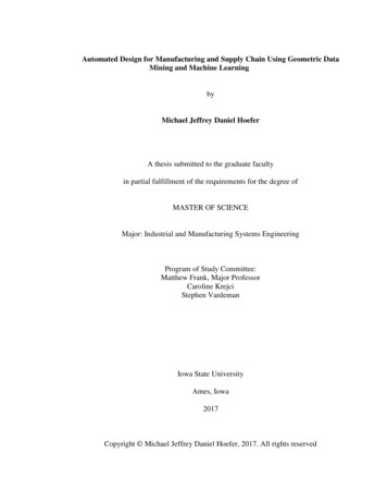
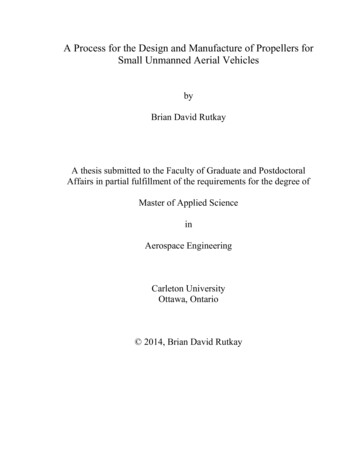
DESIGN AND MANUFACTURE OF A FORMULA SAE INTAKE SYSTEM USINGFUSED DEPOSITION MODELING AND FIBER-REINFORCED COMPOSITEMATERIALSRyan Ilardo, Christopher B. WilliamsDesign, Research, and Education for Additive Manufacturing Systems LaboratoryDepartment of Mechanical EngineeringVirginia Polytechnic Institute and State UniversityRandolph Hall, Blacksburg, VA, 24061-0238(540) 231-3422; cbwilliams@vt.eduABSTRACTIn this paper, the authors discuss the design and manufacture of an intake system for a 600cc FormulaSAE engine. Specifically, Fused Deposition Modeling is used to create an intake system (consisting of aplenum, plenum elbow, and cylinder runners) that is then later covered in layers of carbon fiber compositefabric through vacuum bagging. As a result of this approach, the geometry of the intake system has beenredesigned to result in reduced weight (due to lower material density and lack of welds, hose clamps, andsilicon couples), improved charge distribution, and increased torque through a wide RPM range whencompared to its traditionally-manufactured aluminum counterpart.Keywords: Fused Deposition Modeling, Intake Manifold, Formula SAE1. CONTEXT: INTAKE MANIFOLD OF A FORMULA SAE VEHICLE1.1 Formula SAEFormula SAE is an international student design competition organized by the Society of AutomotiveEngineers (SAE). In this competition, student design teams design, build, and test a small Formula-stylerace car. The teams, acting as contractors for a fictional manufacturing company, are held to strict rulesand design the car as if it were a production item. The car is evaluated via static and dynamic tests. Thestatic evaluations are comprised of an analysis of the car’s cost and design as well as a team presentation.The dynamic testing events include skid pad, acceleration, autocross, and endurance trials.In an effort to create a fuel-efficient, lightweight, cost-effective, and fast automobile, studentscarefully design each component of their vehicle. Subsystems, ranging from the vehicle frame, to thesteering system and the powertrain, are designed by the students, and are frequently manufactured inhouse. In this paper, the authors focus on the design and (additive) manufacture of the intake manifoldsystem of the 2009 Virginia Tech Formula SAE car.1.2 Intake ManifoldWhen designing the engine package for a Formula SAE car, as well as other automotive applications,it is very important to design a quality intake system. The primary function of the intake manifold system(Figure 1) is to deliver combustion air to the engine. Specifically, the primary design goal is to distributethe combustion mixture evenly to each intake port, as doing so improves the engine’s ability to efficientlyand effectively produce torque and power. The geometric design of the intake system affects thevolumetric efficiency of the engine, and thus directly affects the performance of the vehicle.To realize the primary design goal of providing equivalent amounts of air to each cylinder, there areseveral objectives to consider when designing an intake manifold:770
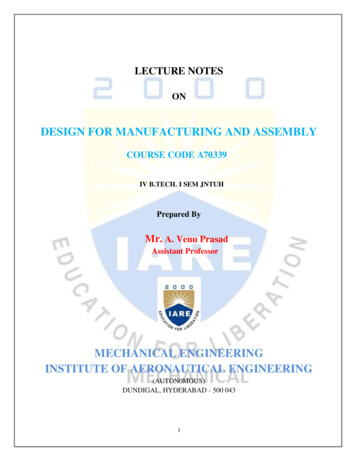
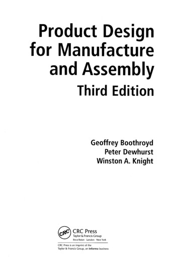
Minimize pressure loss, as pressure loss results in a decrease in output power.Maintain equal static pressure distribution in the plenum, as this will cause the cylinders to pullthe same vacuum, thus leading to even flow in each cylinder.Minimize bends and sudden changes in geometry, as these geometric affects can cause pressureloss.Maximize air velocity into the cylinder, as this provides a better mixture of fuel and air, whichresults in better combustion and performance.Minimize the mass of the system; a common goal of every subsystem of the vehicle.PlenumPlenum ElbowCylinder RunnerFigure 1. 3D rendering of the complete intake assembly.1.3 Intake Manifold ManufactureTraditionally, intake manifold systems are manufactured via bonding multiple aluminum pieces(typically either bent pieces of aluminum tubing or casted aluminum components) together with multiplewelds. An example of the aluminum intake designed and manufactured by the 2008 Virginia TechFormula SAE team is shown in Figure 2. While the use of aluminum provides a structurally soundcomponent with a low mass, this manufacturing technique fundamentally limits the types of manifoldgeometries that can be created. Due to the inherent geometric limitations imposed by the existingmanufacturing process (bending and welding), the team found it difficult to design and fabricate a systemin which (i) pressure losses were kept to a minimum and (ii) equal charge was provided to each cylinder.In this paper a new manufacturing process for fabricating intake manifolds for Formula SAE race carsis presented. Specifically, an intake manifold system is fabricated in a two-step process: (i) a thin-walledABS core is created via Fused Deposition Modeling (FDM) and then (ii) wrapped with layers of carbonfiber via vacuum bag curing. The combined use of additive manufacturing and composite materialsallows for the manufacture of a functional intake with virtually any geometry. This geometric freedomoffered by FDM allows a designer to ensure even static pressure distribution throughout the intake and anequal charge to each cylinder. Furthermore, as FDM allows the creation of the entire manifold system asa single piece, the need for welds and other fasteners is eliminated, resulting in an expected reduction inmass.An overview of the proposed manufacturing process is presented in Section 2. The design andmanufacture of an intake manifold using the process is detailed in Section 3. In Section 4, the authorspresent performance results of the manifold and compare them with manifolds created by more traditionalmeans. Finally, closure is offered in Section 5.771
Figure 2. Intake manifold composed of welded aluminum pieces.2. ADDITIVE MANUFACTURE OF AN INTAKE MANIFOLD2.1 Prior EffortsRecognizing the geometric flexibility offered by additive manufacturing (AM) techniques, engineershave looked to the technologies as a means of improving the design of intake manifold systems for highperformance automobiles. Various AM technologies have been used to create functional prototypes fortesting, to fabricate tooling for creating end-use parts, or to create the end-use parts themselves.Engineers at Jaguar Cars Ltd. have used laser sintering to prototype intake manifolds for functionaltesting. The use of these prototyping techniques increased the amount of design iterations whiledecreasing the financial investment and overall development time for this component [1]. Otherengineers have reported the use of laser sintering [2] and solid ground curing [3] to create intake manifoldprototypes suitable for testing.Additionally, AM techniques have been used to create tooling for the manufacture of end-use intakemanifolds. In these processes, a pattern of the manifold is created via an AM technology and is thentransformed into a functional component either through coating with a carbon fiber composite (followedby removal/dissolution of the pattern) [4,5], or through coating with a ceramic for investment casting withaluminum [6].Finally, many engineers have looked to AM techniques as a means of creating end-use, functionalmanifolds. Specifically, several SAE teams from around the globe (Australia [7], United Kingdom [8, 9],United States [10], and Greece [11]) have used laser sintering (LS) to create functional, race-readymanifolds from sintered nylon. To the authors’ knowledge, laser sintered nylon is the only reported AMtechnique that has been used to create an end-use manifold. Nylon is an appropriate material for thisapplication as it is robust enough to handle the high operating temperatures and pressures of the intakemanifold.772
2.2 Fused Deposition Modeling CompositesLacking access to a LS machine (and having insufficient funds to hire a service bureau), the studentdesign team looked to other AM technologies as a means of creating an end-use manifold. Having accessonly to FDM technology (a Stratasys Dimension SST), the students were aware that it alone would not becapable of producing an end-use part. The standard ABS material (Stratays, P400 [12]) is neither strongenough to withstand the high pressures found in a turbocharged engine, nor it is heat-resistant enough toits high temperatures. While Stratasys does provide high-temperature and high-strength material options(PPSF/PPSU [13], ULTEM 9085 [14]), they can only be processed on Stratays’s higher-end machine line,Fortus. Furthermore, parts created via FDM are not airtight due to pores created by poor optimization ofmaterial flow, filament/roller slippage, liquefier head motion, and build/fill strategies in the extrusiondeposition process [15].In an effort to address these processing deficiencies, the student team proposed a manufacturingprocess in which a thin-shelled, FDM-fabricated part is layered with composite material. Specifically, theteam chose to apply carbon fiber fabric to the ABS part with a high-temperature resin via a vacuumbagging process. This process alleviates the geometric limitations of traditional manifold manufacturingtechniques, and also ensures a light-weight, strong, and heat-resistant component. Additional benefits ofthis process include: While an additional post-processing step is needed in this process when compared to directfabrication using LS (Section 2.1), the equipment required to fabricate the manifold in the proposedprocess is much less expensive; LS machines typically cost more than an order of magnitude greaterthan FDM machines. Thanks to the added strength provided by the carbon fiber composite material, the printed manifoldshell can be very thin (0.12” thick in this specific application), thus saving printed material and alsoreducing part mass. Nylon manifolds that are directly fabricated using LS must be printed thicker tohave comparable strength. The vacuum bagging process cures the resin and hardens the carbon fiber while pulling excess resinout of the part (thus decreasing part weight). Additionally, the vacuum seals the pores present in theFDM-fabricated part as resin is pulled into the structure. Not only does this contribute to partstrength, but it increases its resistivity to heat as the high-temperature resin permeates the part’spores. Compared to lost core fabrication methods, this process requires fewer layers of carbon fiber as theABS shell provides structure and strength. Additionally, the proposed process avoids many of thedifficulties and frustrations typically encountered in the lost core method. The ABS shell ensuresthat the designed interior geometry is not compromised by poor composite adhesion and alsoprecludes the need for the removal of a core. Furthermore, should gaps in the composite fabricoccur during layup, there is no need to restart the process as the ABS shell provides sufficientstrength for operation. Finally, the proposed process does not require the fabrication of a mold inwhich the pattern is created, reducing manufacturing cost and time.3 INTAKE MANIFOLD DESIGN AND MANUFACTURE3.1 Intake Manifold DesignAs the chosen manufacturing process removed prior geometric constraints, the student team wasafforded the opportunity to redesign the intake manifold system geometry. In this redesign process, theirefforts were directed towards two portions of the system: the length and geometry of the cylinder runnersand the geometry of the plenum.The length and geometry of the cylinder runners were the first components designed. Following thecombined use of a dynamometer and computational fluid dynamics (specifically, CFdesign 10.0), a773
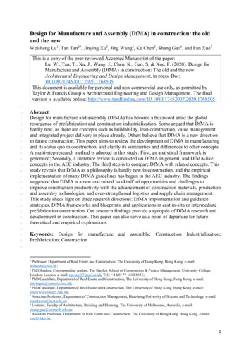
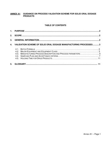
tapered bent design of approximately 11 inches was selected. This length allows for additional air at theparticular RPM range in which the car will operate, thus improving vehicle performance under thesecertain operating conditions. The team chose the bent design because of the need to fit the 11” runnerswithin the packaging constraints of the vehicle.Runner geometry design decisions were dominated by the team’s focus on minimizing pressure lossesat the transition from the plenum to the runner. The team discovered that recirculation could beeliminated by creating large inlets to the runners from the plenum and adding a taper to the runners(Figure 3). In addition, the tapered design increases air flow velocity into the cylinders, giving a bettermixture of fuel and air to the engine and thus providing better combustion and overall performance.Figure 3. Velocity vectors representing air flow as it travels from the plenum to the runners.In designing the plenum, it is important to achieve an even static pressure as this will cause thecylinders to pull the same vacuum, leading to even flow in each cylinder. In order to achieve this goal, adesigner is typically faced with a tradeoff: even static pressures are easily achieved by larger plenumvolumes, however this not only becomes difficult to package, it affects throttle response as a largervolume increases the amount of time for the system to reach an equilibrium pressure. With the ability tocreate a plenum of unlimited geometry, a design was developed that was tapered and could provide aneven static pressure. This tapered design offsets the static pressure that is lost due to friction and otherfactors within the plenum since the taper increases the air velocity as it flows from the entry point to theend. This decrease in size provides gives quick throttle response while keeping an even flow distributionto each cylinder, thus providing increased performance. The final intake manifold system geometry isshown in Figure 4.The improvement in the static pressure distribution over a similar aluminum design from the 2008Virginia Tech Formula SAE team can be observed in Figure 5. The 2009 intake system design is similarto that of the 2008 team, featuring the same runner lengths, entry point, plenum volume, and basic layout.The 2008 system was manufactured from aluminum and has a slightly different geometry due to thelimitations in using that manufacturing technique (specifically, the inability to taper the runners and theplenum). As seen in the graph, the static pressure drop across the plenum is a fraction of that of the 2008design. It should also be noted that the static pressure is much lower in the plenum, which is evidence ofa smaller pressure drop in the system to this point. With an even static pressure, each cylinder pulls thesame vacuum, ensuring that equal amounts of air are provided to each runner, thus increasingperformance.774
Figure 4. Final intake manifold system model.1.2Static Pressure (psi)10.80.60.40.20123Position Based on Cylinder Number42008 Plenum2009 PlenumFigure 5. Comparing the static pressure distribution of the 2008 and 2009 plenum designs.With the interior geometry of the intake system designed, the team turned their attention to the task ofdetailed design of the component. Specifically, features were added to the manifold model for sensormounting and mounts for the fuel injector bosses. The ability to integrate these mounts into the geometryreduced the overall manufacturing time, as it eliminated the time needed to manufacture aluminum piecesto be connected to the manifold.3.2 Intake Manifold ManufactureFollowing final design reviews and simulations, the CAD model was exported to the.stl format forfabrication on the lab’s FDM machine (Stratasys Dimension SST). Due to the constraints of themachine’s build volume (8”x8”x10”), the intake system geometry was modified such that the plenumelbow was built as a separate piece. The two pieces were built using the P400 ABS material. Solublesupport material (P400-SR) was used to ensure the easy removal of support material from the hollowgeometry of the manifold. Once fabricated, the parts were assembled together and bonded using an epoxy(Figure 6).775
Figure 6. Final assembly of the intake manifold.With the assembly step complete, the student team proceeded with the application of the compositematerial onto the manifold. Three layers of carbon fiber fabric were applied to the manifold using a hightemperature resin (PTM&W PT2520). This resin was chosen as it is able to survive the high temperatures( 120 F operating, up to 250 F during heat soak) that are endured from the operation of the engine. Avacuum bagging process was used to lay up the fabric onto the manifold. In addition to curing the resinand ensuring a proper fit of the fabric onto the manifold, the vacuum assisted in drawing the hightemperature resin into the semi-porous ABS part. In addition to adding some strength, the drawn-in ofresin increased the ABS part’s resistivity to heat.The final manifold, featuring the completed composite layup and assembly of all mounts and sensors,is presented in Figure 7. The manifold, as mounted onto the Formula SAE car, is shown in Figure 8.Figure 7. Completed intake system, following the composite layup process and finalassembly of sensors and mounts.The student design time was able to fabricate an end-use intake manifold in just under a week. Theplenum and elbow were fabricated in 60 hours using the FDM machine (including support removal in acleaning solution). An additional 3 days were required for surface and composite work. Thismanufacturing time is much less than the approximately 2 to 3 weeks that it would take to manufacturesimilar pieces in an aluminum, as they would require additional time for design, jig creation, and welding.776
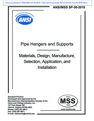
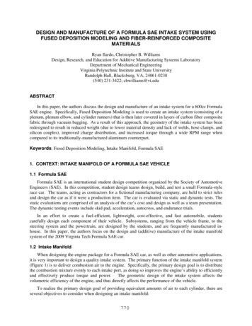
Figure 8. The intake system as mounted onto the 2009 Virginia Tech Formula SAE car4. RESULTSAs stated in Section 1.2, the primary goal in the design of an intake manifold system is to improve theengine’s ability to efficiently and effectively produce torque and power through the even distribution ofthe combustion mixture evenly to each intake port. In order to estimate the flow distribution of thesystem, as well as visualize and analyze the flow to find areas of recirculation and separation that increasepressure drop, simulations were done using CFD. These simulations were then compared with exhaustgas temperature (EGT) data. EGT data can be used to estimate the flow distribution; with more air theEGT data will be high, with more fuel the EGT will be low. The result from these simulations and testscan be seen in Figure 9 and Figure 10. The intake system designs from the 2009 and 2008 teams arecompared in Figure 10.In Figure 10 it is evident that the design changes described in Section 3.1 have improved the flowdistribution across the cylinders. These part-level improvements have transferred to improvements at theoverall engine-level. Specifically, due to the new design, the engine package for 2009 car was able toachieve more torque than that of 2008. The differences in the torque curves of 2008 to 2009 as well asthat of the most powerful natural aspirated (NA) engine at the 2007 competition can be seen in Figure 11.Even though the engine package for 2009 had a lower peak torque, the torque curve is much moreconsistent over a longer range of RPMs, improving the drivability of the vehicle - a major design goal forthe 2009 student team. The 2009 turbocharged engine also produced more torque throughout thecomplete RPM range over the naturally aspirated engine. The 2009 engine maintained a higher torquethan the 2007 NA engine for a range of 6000 RPM compared to a 4700 RPM range for the 2008 engine.These improvements over previous designs are due largely to the new manufacturing process of the intakesystem, which enabled the design of a manifold that provided a more even flow distribution to eachcylinder and a reduction of pressure losses.777
Distribution of Flow (%)30.0025.0020.0015.0010.005.000.00123Cylinder NumberEGT Distribution4CFD PredictionsFigure 9. Flow distribution into each cylinder based on CFD and EGT data.Distribution of Flow (%)30.0025.0020.0015.0010.005.000.00123Cylinder Number2009 Intake42008 IntakeFigure 10. Comparing the flow distribution of the 2009 and 2008 intake systems.Figure 11. Comparing the torque of the 2009 turbocharged engine, the 2008 turbochargedengine, and the most powerful NA engine at the 2007 competition.778
5. CLOSUREIn this paper, the authors present a manufacturing process used to create an intake manifold for aFormula SAE car. Specifically, an intake manifold shell is first printed using Fused DepositionModeling; composite material is then applied to the shell with a high temperature resin and a vacuumbagging process. The use of FDM provided geometric flexibility in the design of the manifold, while theuse of composite material and high-temperature resin ensured that the system would have sufficientstrength and heat-resistivity to survive the operating environment of the turbo-charged engine.The use of FDM provided the student design team the freedom to create a unique intake geometrythat featured a tapered plenum and tapered runners. These geometric features provided an even staticpressure throughout the system, an equal charge to each cylinder, reduced pressure loss, and an increasedair velocity into the cylinders - key goals in manifold design. The use of the additive manufacturingtechnology ensured the creation of a system free from sudden geometry changes, which reduce flowseparation and increase pressure loss.The manifold that resulted from the process greatly improved the performance of the Formula SAEengine, as compared to a similar aluminum design. The new design provided an increase in torque overan extended RPM range as the manufacturing process provided the ability to create a complex geometrythat provided equal air to each cylinder and reduced total pressure drop. Additionally, relative to theprevious design, the total weight of the system was reduced from 2.875 lbm to 2.24 lbm (a 22% decrease).6. REFERENCES1. Jackson, S., 2008, “From Rapid Prototyping to Mass Customization,” Industrial Laser Solutions forManufacturing, http://www.industrial-lasers.com/articles/article display.html?id 333159, accessedJuly 2009.2. Gebhardt, A., 2003, Rapid Prototyping, Hanser.3. Abbott, P., 1998, “Rapid Prototyping,” Assembly Automation, Vol. 18, Iss. 1, Mini-feature.4. Dore, S., P. Lavallee, 1997, “Design and Fabrication of Intake Manifold for Formula SAE (Society ofAutomotive Engineers) Race Car,” Rapid Product Development Technologies, P. Boulanger (ed.),pp. 187-197.5. “Hi-Tech Hot Rod is the Ultimate Learning Lab,” 2005, 2005/01/050125085013.htm., accessed July 2009.6. “Rapid Prototyping System Helps Students Create a Formula Car,” January 1998, Modern MachineShop, g-system-helps-students-create-aformula-car.aspx, accessed July 2009.7. Envizage, “QUT Motorsport - SLS Rapid Manufactures,” Envizage Case Study,http://www.envizage.com.au/case studies/case study 14.php, accessed July 2009.8. 3T RPD Ltd., “Formula Student achieves top marks with 3T,” 3T RPD Ltd. Case a-student.htm, accessed July 2009.9. Hopkinson, N., R. J. M. Hague, P. M. Dickens, 2006, Rapid Manufacturing: An Industrial Revolutionfor the Digital Age, John Wiley & Sons Ltd., West Sussex, England.10. 3D Systems, 2009, “University Race Team Benefits from Sintered Engine System,” A 3D SystemsSuccess success stories/OSU SLS Case Study.pdf, accessedJuly 2009.779
11. Mihailidis, A., Z. Samaras, I. Nerantzis, G. Fontaras, G. Karaoglanidis, 2009, “The Design of aFormula Student Race Car; A Case Study,” Proceedings of the Institution of Mechanical Engineers.Part D, Journal of Automobile Engineering, Vol. 223, Iss. 6, pp. 805-818.12. Stratasys, 2009, “P400 ABS Material Specification Sheet,” Redeye,http://redeyeondemand.com/Downloads/MSpec ABS.pdf, accessed July 2009.13. Stratasys, 2009, “Polyphenylsulfone Specification Sheet,” Redeye,http://redeyeondemand.com/Downloads/MSpec PPSF.pdf, accessed July 2009.14. Stratasys, 2009, “ULTEM 9085 Specification Sheet,” Fortus,http://www.fortus.com/uploadedFiles/North US-0109.pdf, accessed July 2009.15. Agarwala, M. K., V. R. Jamalabad, N. A. Langrana, A. Safari, P. J. Whalen and S. C. Danforth, 1996,"Structural Quality of Parts Processed by Fused Deposition," Rapid Prototyping Journal, Vol. 2, No.4, pp. 4-19.780
DESIGN AND MANUFACTURE OF A FORMULA SAE INTAKE SYSTEM USING . fabric through vacuum bagging. As a result of this approach, the geometry of the intake system has been . (AM) techniques, engineers have looked to the technologies as a means of improving the