Transcription
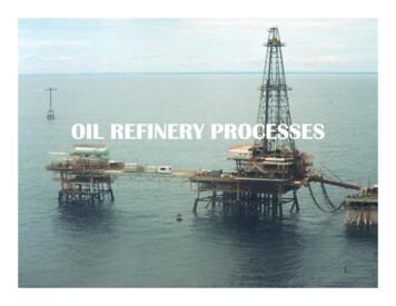
OIL REFINERY PROCESSES1
World Crude Oil RefineriesSource: http://bbs.keyhole.com/ubb/ubbthreads.php?ubb showthreaded&Number 1197575&site id 1#import
Refining operationsPetroleum refining processes and operations can be separated into five basicareas: Fractionation (distillation) is the separation of crude oil in atmospheric andvacuum distillation towers into groups of hydrocarbon compounds ofdiffering boiling-point ranges called "fractions" or "cuts." Conversion Processes change the size and/or structure of hydrocarbonmolecules. These processes include: :– Decomposition (dividing) by thermal and catalytic cracking;– Unification (combining) through alkylation and polymerization; and– Alteration (rearranging) with isomerization and catalytic reforming. Treatment Processes to prepare hydrocarbon streams for additionalprocessing and to prepare finished products. Treatment may include removalor separation of aromatics and naphthenes, impurities and undesirablecontaminants. Treatment may involve chemical or physical separation e.g.dissolving, absorption, or precipitation using a variety and combination ofprocesses including desalting, drying, hydrodesulfurizing, solvent refining,sweetening, solvent extraction, and solvent dewaxing.3
Refining operations Formulating and Blending is the process of mixing andcombining hydrocarbon fractions, additives, and othercomponents to produce finished products with specificperformance properties. Other Refining Operations include:–––––––light-ends recovery;sour-water stripping;solid waste, process-water and wastewater treatment;cooling, storage and handling and product movement;hydrogen production;acid and tail-gas treatment;and sulfur recovery.4
Modern Petroleum ProcessingSeven Basic Operations in Petroleum Processing5
Physical and chemical processesPhysicalDistillationSolvent extractionPropane deasphaltingSolvent gDelayed cokingFlexicokingHydrotreatingCatalytic reformingCatalytic crackingHydrocrackingCatalytic dewaxingAlkylationPolymerizationIsomerization6
Typical layout for an oil refinery7
PETROCHEMICAL PRODUCT TREEBuilding BlockIntermediateDownstream TPVCPBRSBR-Ethylene dichlorideEthylene oxideEthylene glycolDimethyl terephathalatePolyvinyl chloridePolybutadiene rubberStyrene butadiene rubberEO/EGIsopropyl Alcohol/AcetonePropylenePolypropyleneGlycol EthersEnthaloaminesDye Stuff andChemicalsIntermediateAcrylonitrileAcrylic FiberPlasticisers2 Ethyl HexanolOlefinsA B S kylateThermoset ResinsNylonDetergentPolyesterAromaticsMaleic AnhydridePhthalicAnhydrideXyleneDMTAlkyd ResinsPlasticisersPolyesterFibre
Products Made byPetroleum IndustrytheU.S.In general, the products whichdictate refinery design arerelatively few in number, andthe basic refinery processes arebased on the large-quantityproducts such as gasoline,diesel, jet fuel, and homeheating oils.9
DESALTING10
Crude oil distillation is more complicated than product distillation,in part because crude oils contain water, salts, and suspendedsolids. Step 1 in the refining process is to remove these contaminants so asto reduce corrosion, plugging, and fouling of equipment and toprevent poisoning catalysts in processing units. Step 2 most typical methods of crude-oil desalting are chemicaland electrostatic separation, and both use hot water as theextraction agent. In chemical desalting, water and chemical surfactant (demulsifiers)are added to the crude, which is heated so that salts and otherimpurities dissolve or attach to the water, then held in a tank tosettle out. Electrical desalting is the application of high-voltage electrostaticcharges to concentrate suspended water globules in the bottom ofthe settling tank. Surfactants are added only when the crude has alarge amount of suspended solids. Step 3(and rare) process filters hot crude using diatomaceous earth.11
The salts are dissolved in the wash water and the oil and waterphases separated in a settling vessel either by adding chemicalsto assist in breaking the emulsion or by developing a highpotential electrical field across the settling vessel to coalesce thedroplets of salty water more rapidly. Either AC or DC fields may be used and potentials from 12,000to 35,000 volts are used to promote coalescence. For single-stage desalting units 90 to 95% efficiencies areobtained and two-stage processes achieve 99% or betterefficiency. If the pH of the brine exceeds 7, emulsions can be formedbecause of the sodium naphthenate and sodium sulfide Present. For most crude oils it is desirable to keep the pH below 8.0.Better dehydration is obtained in electrical desalters when theyare operated in the pH range of 6 to 8 with the best dehydrationobtained at a pH near 6. The pH value is controlled by using another water source or by12the addition of acid to the inlet or recycled water.
The crude oil feedstock is heated to 65-180 C to reduce viscosityand surface tension for easier mixing and separation of the water. The temperature is limited by the vapor pressure of the crude-oilfeedstock. In both methods other chemicals may be added. Ammonia is oftenused to reduce corrosion. Caustic or acid may be added to adjustthe pH of the water wash. Wastewater and contaminants are discharged from the bottom ofthe settling tank to the wastewater treatment facility.13
Single stage electrostatic desaltingsystems14
Two-stage electrostatic desaltingsystems15
Desalting/dehydration16
Industrial process furnaces17
Fuel flows into the burner and is burnt with air provided from anair blower. There can be more than one burner in a particularfurnace which can be arranged in cells which heat a particular setof tubes. Burners can also be floor mounted, wall mounted or roof mounteddepending on design. The flames heat up the tubes, which in turn heat the fluid inside inthe first part of the furnace known as the radiant section or firebox. The heating fluid passes through the tubes and is thus heated to thedesired temperature. The gases from the combustion are known as flue gas. After theflue gas leaves the firebox, most furnace designs include aconvection section where more heat is recovered before venting tothe atmosphere through the flue gas stack. (HTF Heat TransferFluid. This heated fluid is then circulated round the whole plant to heatexchangers to be used wherever heat is needed instead of directlyheating the product line as the product or or material may bevolatile or prone to cracking at the furnace temperature.)18
Schematic diagramof an industrialprocess furnace19
1. Radiant section20
2. Convection section21
The convection section, is located above the radiant sectionwhere it is cooler to recover additional heat. Heat transfer takes place by convection here, and the tubesare finned to increase heat transfer. The first two tube rows in the bottom of the convectionsection and at the top of the radiant section is an area ofbare tubes (without fins) because they are still exposed toplenty of radiation from the firebox Crossover is the term used to describe the tube thatconnects from the convection section outlet to the radiantsection inlet. The sightglass at the top allows personnel to see the flameshape and pattern from above and visually inspect if flameimpingement is occurring. Flame impingement happens when the flame touches thetubes and causes small isolated spots of very high22temperature.
3. Burner23
4. Soot blowers Soot blowers are found in the convection section. As this section is above the radiant section and airmovement is slower because of the fins, soot tends toaccumulate here. Soot blowing is normally done when the efficiency of theconvection section is decreased. Soot blowers utilize flowing media such as water, air orsteam to remove deposits from the tubes. This is typicallydone during maintenance with the air blower turned on.24
5. Stack As the damper closes, the amount ofheat escaping the furnace through thestack decreases, but the pressure ordraft in the furnace increases whichposes risks to those working around it if there are air leakages in the furnacethe flames can then escape out of thefirebox or even explode if the pressureis too great.25
6. Insulation Insulation is an important part of the furnace because itprevents excessive heat loss. Refractory materials such as firebrick, castable refractoriesand ceramic fibre, are used for insulation.26
DISTILATION27
Distillation is based on the fact that the vapour of a boilingmixture will be richer in the components that have lowerboiling points. Thus, when this vapour is cooled and condensed, thecondensate will contain the more volatile components. Atthe same time, the original mixture will contain more ofthe less volatile components. Fractional distillation is useful for separating a mixture ofsubstances with narrow differences in boiling points, and isthe most important step in the refining process. Distillation can contribute to more than 50% of plantoperating costs. Very few of the components come out of the fractionaldistillation column ready for market.28
Distillation column withbubble-cap trays29
1. Atmospheric distillation in the refining process is the separation of crude oil into various fractionsor straight-run cuts by distillation in atmospheric and vacuum towers. The main fractions or "cuts" obtained have specific boiling-point rangesand can be classified in order of decreasing volatility into gases, lightdistillates, middle distillates, gas oils, and residuum. The desalted crude feedstock is preheated using recovered process heat.The feedstock then flows to a direct-fired crude charge heater then intothe vertical distillation column just above the bottom, at pressures slightlyabove atmospheric and at temperatures ranging from 340-370 C (abovethese temperatures undesirable thermal cracking may occur). All but theheaviest fractions flash into vapor. As the hot vapor rises in the tower, its temperature is reduced. Heavy fuel oil or asphalt residue is taken from the bottom. At successively higher points on the tower, the various major productsincluding lubricating oil, heating oil, kerosene, gasoline, anduncondensed gases (which condense at lower temperatures) are drawnoff.30
The temperature of crude oil is raised to about 288 C by heatexchange with product and reflux streams. It is then further heated to about 399 C in a furnace andcharged to the flash zone of the atmospheric fractionators. The furnace discharge temperature is sufficiently high 343 to399 C to cause vaporization of all products withdrawn abovethe flash zone plus about 10 to 20% of the bottoms product. Reflux is provided by1. condensing the tower overhead vapors and returning aportion of the liquid to the top of the tower2. pump-around and pump back streams lower in the tower. Each of the side stream products removed from the towerdecreases the amount of reflux below the point of draw off. Maximum reflux and fractionation is obtained by removingall heat at the top of the tower, but this results in an invertedcone-type liquid loading which requires a very large diameter31at the top of the tower.
To reduce the top diameter of the tower and even the liquid loadingover the length of the tower, intermediate heat-removal streams areused to generate reflux below the sidestream removal points. Toaccomplish this, liquid is removed from the tower, cooled by a heatexchanger, and returned to the tower or, alternatively, a portion of thecooled sidestream may be returned to the tower. This cold streamcondenses more of the vapors coming up the lower and therebyincreases the reflux below that point. Although crude towers do not normally use reboilers, several traysare generally incorporated below the flash zone and steam isintroduced below the bottom tray to strip any remaining gas oil fromthe liquid in the flash zone and to produce a high-flash-point bottoms. The atmospheric fractionator normally contains 30 to 50 fractionationtrays. Separation of the complex mixtures in crude oils is relatively easyand generally five to eight trays are needed for each sidestreamproduct plus the same number above and below the feed plate. Thus,a crude oil atmospheric fractionation tower with four liquid32sidestream drawoffs will require from 30 to 42 trays.
The liquid sidestream withdrawn from the tower will containlow-boiling components which lower the flashpoint. These‘‘light ends’’ are stripped from each sidestream in a separatesmall stripping tower containing four to ten trays with steamintroduced under the bottom tray. The steam and stripped lightends are vented back into the vapor zone of the atmosphericfractionator above the corresponding side-draw tray. The overhead condenser on the atmospheric tower condensesthe pentane and- heavier fraction of the vapors that passes out ofthe top of the tower. This is the light gasoline portion of theoverhead, containing some propane and butanes and essentiallyall of the higher-boiling components in the tower overheadvapor. Some of this condensate is returned to the top of thetower as reflux, and the remainder is sent to the stabilizationsection of the refinery gas plant where the butanes and propaneare separated from the C5-180 F (C5-82 C) LSR gasoline. 33
Simple crude distillation34
35
2. Vacuum distillation The furnace outlet temperatures required for atmospheric pressure distillation ofthe heavier fractions of crude oil are so high that thermal cracking would occur,with the resultant loss of product and equipment fouling. The process takes place in one or more vacuum distillation towers. The principles of vacuum distillation resemble those of fractional distillationexcept that larger diameter columns are used to maintain comparable vaporvelocities at the reduced pressures. The internal designs of some vacuum towers are different from atmospherictowers in that random packing is used instead of trays. A typical first-phase vacuum tower may produce gas oils, lubricating-oil basestocks, and heavy residual for propane deasphalting. A second-phase tower operating at lower vacuum may distill surplus residuumfrom the atmospheric tower, which is not used for lube-stock processing, andsurplus residuum from the first vacuum tower not used for deasphalting. Vacuum towers are typically used to separate catalytic cracking feedstock fromsurplus residuum. .36
Distillation is carried out with absolute pressures in the towerflash zone area of 25 to 40 mmHg. Addition of steam to the furnace inlet increases the furnace tubevelocity and minimizes coke formation in the furnace as well asdecreasing the total hydrocarbon partial pressure in the vacuumtower. Furnace outlet temperatures are also a function of the boilingrange of the feed and the fraction vaporized as well as of thefeed coking characteristics. furnace outlet temperatures in the range of 388 to 454 C aregenerally used The lower operating pressures cause significantincreases in the volume of vapor per barrel vaporized and, as aresult, the vacuum distillation columns are much larger indiameter than atmospheric towers. It is not unusual to havevacuum towers up to 40 feet in diameter.37
38
Modern crude distillation39
40
3. Light End Fractionation Within refineries there are numerous other, smallerdistillation towers called columns, designed to separatespecific and unique products. Columns all work on the same principles as the towersdescribed above. For example, a depropanizer is a small column designed toseparate propane and lighter gases from butane and heaviercomponents in the light end unit.41
42
4. Propane deasphalting Coke-forming tendencies of heavier distillation productsare reduced by removal of asphaltenic materials by solventextraction. Liquid propane is a good solvent (butane and pentane arealso commonly used). Deasphalting is based on solubility of hydrocarbons inpropane. Vacuum residue is fed to a countercurrent deasphaltingtower. Alkanes dissolve in propane whereas asphaltenic materials(aromatic compounds), ‘coke-precursors’ do not. Asphalt is sent for thermal processing.43
44
5. Solvent extraction and dewaxing Solvent treating is a widely used method of refining lubricating oils aswell as a host of other refinery stocks. Since distillation (fractionation) separates petroleum products intogroups only by their boiling-point ranges, impurities may remain.These include:1. organic compounds containing sulfur, nitrogen, and oxygen2. inorganic salts3. dissolved metals4. soluble salts that were present in the crude feedstock. In addition, kerosene and distillates may have trace amounts ofaromatics and naphthenes, and lubricating oil base-stocks may containwax. Solvent refining processes including solvent extraction and solventdewaxing usually remove these undesirables at intermediate refiningstages or just before sending the product to storage.45
The purpose of solvent extraction is to prevent corrosion,protect catalyst in subsequent processes, and improve finishedproducts by removing unsaturated, aromatic hydrocarbons fromlubricant and grease stocks. The solvent extraction process separates aromatics, naphthenes,and impurities from the product stream by dissolving orprecipitation. The feedstock is first dried and then treated using a continuouscountercurrent solvent treatment operation. In one type of process, the feedstock is washed with a liquid inwhich the substances to be removed are more soluble than in thedesired resultant product. In another process, selected solvents are added to causeimpurities to precipitate out of the product. In the adsorption process, highly porous solid materials collectliquid molecules on their surfaces.46
The solvent is separated from the product stream by heating,evaporation, or fractionation, and residual trace amounts aresubsequently removed from the raffinate by steam stripping orvacuum flashing. The most widely used extraction solvents are phenol, furfural,and cresylic acid. Other solvents less frequently used are liquid sulfur dioxide,nitrobenzene, and 2,2' dichloroethyl ether. The selection of specific processes and chemical agentsdepends on the nature of the feedstock being treated, thecontaminants present, and the finished product requirements.47
Aromatic solvent extraction unit48
Solvent dewaxing Solvent dewaxing is used to remove wax from either distillate or residualbasestock at any stage in the refining process.There are several processes in use for solvent dewaxing, but all have thesame general steps, which are::––– mixing the feedstock with a solvent;precipitating the wax from the mixture by chillingrecovering the solvent from the wax and dewaxed oil for recycling bydistillation and steam stripping.Usually two solvents are used: toluene, which dissolves the oil andmaintains fluidity at low temperatures, and methyl ethyl ketone (MEK),which dissolves little wax at low temperatures and acts as a waxprecipitating agent.Other solvents sometimes used include benzene, methyl isobutyl ketone,propane, petroleum naphtha, ethylene dichloride, methylene chloride, andsulfur dioxide.In addition, there is a catalytic process used as an alternate to solventdewaxing.49
Solvent dewaxing unit50
6. Blending Blending is the physical mixture of a number of differentliquid hydrocarbons to produce a finished product withcertain desired characteristics. Products can be blended in-line through a manifoldsystem, or batch blended in tanks and vessels. In-line blending of gasoline, distillates, jet fuel, andkerosene is accomplished by injecting proportionateamounts of each component into the main stream whereturbulence promotes thorough mixing. Additives including octane enhancers, anti-oxidants, antiknock agents, gum and rust inhibitors, detergents, etc. areadded during and/or after blending to provide specificproperties not inherent in hydrocarbons.51
CRUDE DISTILLATION UNIT PRODUCTS Fuel gas. The fuel gas consists mainly of methane andethane. In some refineries, propane in excess of LPGrequirements is also included in the fuel gas stream. Thisstream is also referred to as ‘‘dry gas.’’ Wet gas. The wet gas stream contains propane and butanesas well as methane and ethane. The propane and butanesare separated to be used for LPG and, in the case ofbutanes, for gasoline blending and alkylation unit feed. LSR naphtha. The stabilized LSR naphtha (or LSRgasoline) stream is desulfurized and used in gasolineblending or processed in an isomerization unit to improve52octane before blending into gasoline.
HSR naphtha or HSR gasoline. The naphtha cuts aregenerally used as catalytic reformer feed to produce highoctane reformate for gasoline blending and aromatics. Gas oils. The light, atmospheric, and vacuum gas oils armprocessed in a hydrocracker or catalytic cracker to producegasoline, jet, and diesel fuels. The heavier vacuum gas oilscan also be used as feedstocks for lubricating oilprocessing units. Residuum. The vacuum still bottoms can be processed in avisbreaker, coker, or deasphalting unit to produce heavyfuel oil or cracking and/or lube base stocks. For asphaltcrudes, the residuum can be processed further to produceroad and/or roofing asphalts.53
EO/EG EDC 2 Ethyl Hexanol Acrylonitrile P V C Acrylic Fiber Glycol Ethers Enthaloamines Polyethylene (Ld/Hd) A B S Plastics P B R Plasticisers Polypropylene Dye Stuff and Chemicals Intermediate Building Block Intermediate Downstream Products EDC - Ethylene dichloride EO - Ethylene oxide EG - Ethyl