Transcription
Dell PowerEdge R220Owner's ManualRegulatory Model: E10SRegulatory Type: E10S003
Notes, cautions, and warningsNOTE: A NOTE indicates important information that helps you make better use of your computer.CAUTION: A CAUTION indicates either potential damage to hardware or loss of data and tells youhow to avoid the problem.WARNING: A WARNING indicates a potential for property damage, personal injury, or death.Copyright 2015 Dell Inc. All rights reserved. This product is protected by U.S. and international copyright andintellectual property laws. Dell and the Dell logo are trademarks of Dell Inc. in the United States and/or otherjurisdictions. All other marks and names mentioned herein may be trademarks of their respective companies.2015 - 05Rev. A02
Contents1 About your system. 7Front-panel features and indicators. 7Back-panel features and indicators.9NIC indicator codes. 10Related documentation. 11Quick Resource Locator. 112 Using the System Setup and Boot Manager.12Choosing the system boot mode. 13Entering System Setup. 13Responding to error messages. 13Using the system setup navigation keys. 13System Setup options.14System and setup password features. 22Entering the UEFI boot manager. 24Embedded system management.26iDRAC Settings Utility. 263 Installing and removing system components. 27Recommended tools.27Front bezel (optional). 27Installing the front bezel.27Removing the front bezel. 28Opening and closing the system.28Opening the system. 28Closing the system.29Inside the system.29Chassis intrusion switch. 30Removing the chassis intrusion switch.31Installing the chassis intrusion switch. 32Optical drive (optional).32Removing the optical drive . 32Installing the optical drive . 33Hard drives.34Removing a 3.5 inch hard-drive cage. 34Installing a 3.5 inch hard-drive cage. 36Removing a 3.5 inch hard drive from the hard-drive cage. 36Installing a 3.5 inch hard drive into the hard-drive cage. 373
Removing a 2.5 inch hard-drive cage. 38Installing a 2.5 inch hard-drive cage. 39Removing a 2.5 inch hard drive from the hard-drive cage. 39Installing a 2.5 inch hard drive into the hard-drive cage.40LED module.40Removing the LED module.40Installing the LED module. 41Control-panel board.42Removing the control-panel board.42Installing the control-panel board.43Cooling fans. 44Removing a cooling fan.44Installing a cooling fan. 45Cooling shroud. 46Removing the cooling shroud. 46Installing the cooling shroud. 47System memory. 47General memory module installation guidelines.48Sample memory configurations. 48Removing memory modules. 49Installing memory modules. 50Internal USB memory key (optional).51Removing and installing the internal USB key.52Expansion cards and expansion-card risers.52Expansion card installation guidelines.52Expansion card types and form factor. 53Removing an expansion card.53Installing an expansion card. 54Removing the expansion-card riser. 55Installing the expansion-card riser. 56iDRAC7 Enterprise card (optional).56Removing the iDRAC7 Enterprise card.56Installing the iDRAC7 Enterprise card. 57System battery.58Replacing the system battery. 58Processor.59Removing the processor.59Installing the processor. 61Power supply unit. 62Removing the power supply unit.63Installing the power supply unit. 64System board. 644
Removing the system board.64Installing the system board. 654 Troubleshooting your system. 67Safety first—for you and your system.67Troubleshooting system startup failure.67Troubleshooting external connections. 67Troubleshooting the video subsystem. 67Troubleshooting a USB device. 68Troubleshooting a serial I/O device. 68Troubleshooting a NIC. 68Troubleshooting a wet system. 69Troubleshooting a damaged system.70Troubleshooting the system battery. 70Troubleshooting the power supply.71Troubleshooting cooling problems. 71Troubleshooting cooling fans. 71Troubleshooting system memory. 72Troubleshooting an internal USB key. 73Troubleshooting an SD card. 73Troubleshooting an optical drive.74Troubleshooting a hard drive. 74Troubleshooting expansion cards. 75Troubleshooting the processor. 765 Using system diagnostics. 77Dell Embedded System Diagnostics. 77When to use the embedded system diagnostics. 77Running the embedded system diagnostics. 77System diagnostics controls. 786 Jumpers and connectors. 79System board jumper settings. 79System board connectors. 80Disabling a forgotten password. 817 Technical specifications. 828 System messages.86System error messages.86Warning messages. 95Diagnostic messages. 955
Alert messages. 969 Getting help. 97Contacting Dell. 97Locating your system service tag. 97Documentation feedback. 97Quick Resource Locator.986
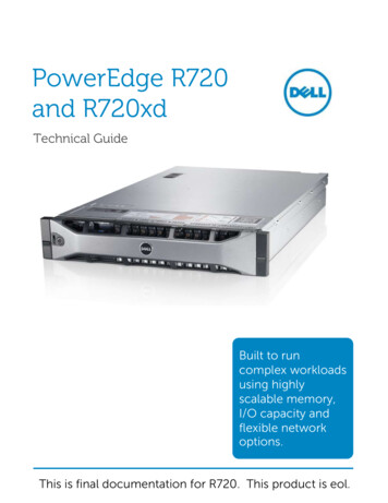
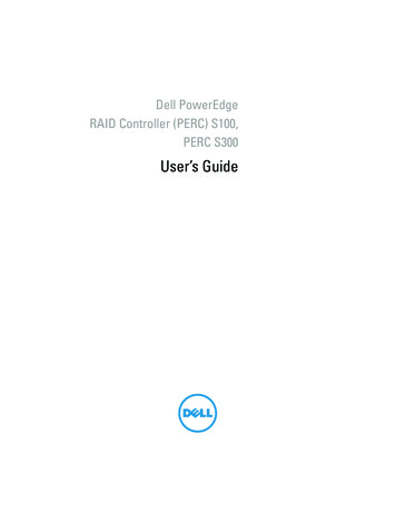
1About your systemFront-panel features and indicatorsFigure 1. Front-panel features and indicatorsItemIndicator, button, orconnector1Power-on indicator,power buttonIconDescriptionThe power-on indicator lights when the systempower is on. The power button controls the powersupply output to the system.NOTE: On ACPI-compliant operating systems,turning off the system using the power buttoncauses the system to perform a gracefulshutdown before power to the system isturned off.2NMI buttonUsed to troubleshoot software and device drivererrors when running certain operating systems.This button can be pressed using the end of apaper clip.Use this button only if directed to do so byqualified support personnel or if the information isprovided in the operating system documentation.3Video connectorAllows you to connect a VGA display to the system.4Health indicatorIf the system is on, and in good health, theindicator lights solid blue.The indicator blinks amber if the system is on or instandby, and any error exists (for example, a failedfan or hard drive).7
ItemIndicator, button, orconnectorIconDescription5Hard-drive indicatorThe indicator blinks green to indicate hard-driveactivity.6Electrical indicatorThe indicator blinks amber if the systemexperiences an electrical error (for example,voltage out of range, or a failed power supply orvoltage regulator).See the System Event Log or system messages forthe specific issue. Re-seat the power supply byremoving and reinstalling it. If the problem persists,see Getting help.7Temperature indicatorThe indicator blinks amber if the systemexperiences a thermal error (for example, atemperature out of range or fan failure).Ensure that none of the following conditions exist: A cooling fan is removed or has failed.System cover, cooling shroud, EMI filler panel,memory-module blank, or back-filler bracket isremoved.Ambient temperature is too high.External airflow is obstructed.See Getting help.8System status indicatorLights blue during normal system operation.Lights amber when the system needs attention dueto a problem. See the System Event Log or system messagesfor the specific issue. Invalid memory configurations can cause thesystem to halt at startup without any videooutput. See Getting help.9System identificationbuttonThe identification buttons on the front and backpanels can be used to locate a particular systemwithin a rack. When one of these buttons ispressed, the system status indicator on the frontand the back of the system flashes until one of thebuttons is pressed again.Press to toggle the system ID on and off.If the system stops responding during POST, pressand hold the system ID button for more than fiveseconds to enter BIOS progress mode.To reset iDRAC (if not disabled in the iDRACSettings option) press and hold the button formore than 15 seconds.8
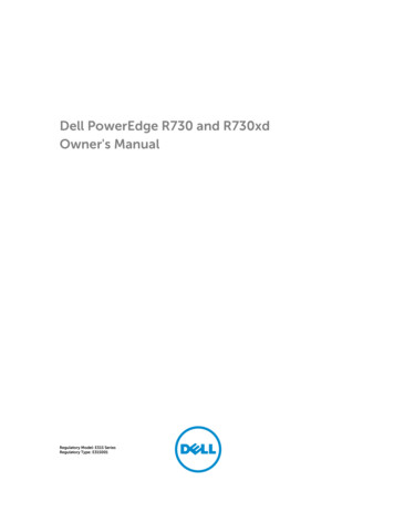
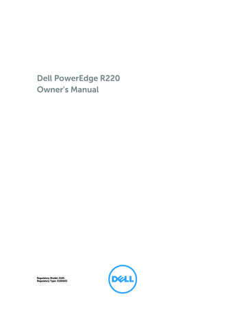
ItemIndicator, button, orconnectorIconDescription10USB connectors (2)Allow you to connect USB devices to the system.The ports are USB 2.0-compliant.11System service tagA slide-out label panel that allows you to recordsystem information such as Service Tag, NIC, MACaddress, and so on as per your need.12Optical drive (optional)One optional slim SATA DVD-ROM drive or DVD /-RW drive.Back-panel features and indicatorsFigure 2. Back-panel features and indicatorsItemIndicator, button, orconnectorIconDescription1iDRAC7 Enterprise port(optional)Dedicated management port for the iDRAC7Enterprise card.2vFlash media card slot(optional)Allows you to connect the optional vFlash mediacard.3Serial connectorAllows you to connect a serial device to thesystem.4PCIe expansion card slotAllows you to connect one low-profile PCI Expressexpansion card.5Video connectorAllows you to connect a VGA display to thesystem.6eSATAAllows you to connect additional storage devices.7USB connectors (2)Allow you to connect USB devices to the system.The ports are USB 3.0-compliant.8Ethernet connectors (2)Two integrated 10/100/1000 Mbps NICconnectors.9System status indicatorIndicates the status of the system. Lights blueduring normal system operation. Lights amberwhen the system needs attention due to aproblem.9
ItemIndicator, button, orconnector10System identificationbuttonIconDescriptionThe identification buttons on the front and backpanels can be used to locate a particular systemwithin a rack. When one of these buttons ispressed, the system status indicator on the backflashes until one of the buttons is pressed again.Press to toggle the system ID on and off.If the system stops responding during POST, pressand hold the system ID button for more than fiveseconds to enter BIOS progress mode.To reset iDRAC (if not disabled in the iDRACSettings option) press and hold the button formore than 15 seconds.11Power supply250 W AC power supply.12Retention clipSecures the power cable.NIC indicator codesFigure 3. NIC indicator1.link indicator2.activity indicatorIndicatorIndicator codeLink and activityindicators are offThe NIC is not connected to the network.Link indicator isgreenThe NIC is connected to a valid network at its maximum port speed (1 Gbps or 10Gbps).Link indicator isamberThe NIC is connected to a valid network at less than its maximum port speed.Activity indicator is Network data is being sent or received.blinking green10
Related documentationWARNING: See the safety and regulatory information that shipped with your system. Warrantyinformation may be included within this document or as a separate document.NOTE: For all Dell Storage documentation, go to Dell.com/support and enter the system ServiceTag to get your system documentation.NOTE: For all Dell OpenManage documents, including the Dell OpenManage Server AdministratorUser Guide, go to Dell.com/openmanagemanuals.NOTE: For all OS documents, go to Dell.com/operatingsystemmanuals .Your product documentation includes: The Getting Started Guide provides an overview of system features, setting up your system, andtechnical specifications. This document is also shipped with your system. The Set-up Placemat provides an overview of setting up, cabling, and configuring your system. The Owner’s Manual provides information about system features and describes how to troubleshootthe system and install or replace system components. The Administrator’s Guide provides information about configuring and managing the system. The Troubleshooting Guide provides information about troubleshooting the software and the system. The Dell OpenManage Server Administrator User’s Guide provides information about using theOpenManage Server Administrator to manage your Dell Storage NAS system.NOTE: For more information and updates, go to Dell.com/support/manuals and read the updatesfirst because they often supersede information in other documents.NOTE: For more information and updates, go to Dell.com/storagemanuals and read the updatesfirst because they often supersede information in other documents.Quick Resource LocatorUse the Quick Resource Locator (QRL) to get immediate access to system information and how-tovideos. This can be done by visiting Dell.com/QRL or by using your smartphone and a model specificQuick Resource (QR) code located on your Dell PowerEdge system. To try out the QR code, scan thefollowing image.11
Using the System Setup and BootManager2System Setup enables you to manage your system hardware and specify BIOS-level options.The following keystrokes provide access to system features during startup:KeystrokeDescription F2 Enters the System Setup. F10 Enters System Services, which opens the DellLifecycle Controller 2 (LC2). The Dell LC2 supportssystems management features such as operatingsystem deployment, hardware diagnostics,firmware updates, and platform configuration,using a graphical user interface. The exact LC2feature set is determined by the iDRAC licensepurchased. For more information, see the Dell LC2documentation at Dell.com/esmmanuals. F11 Enters the BIOS Boot Manager or the UnifiedExtensible Firmware Interface (UEFI) Boot Manager,depending on the system's boot configuration. F12 Starts Preboot Execution Environment (PXE) boot.From the System Setup, you can: Change the NVRAM settings after you add or remove hardware. View the system hardware configuration. Enable or disable integrated devices. Set performance and power management thresholds. Manage system security.You can access the System Setup using the: Standard graphical browser, which is enabled by default. Text browser, which is enabled using Console Redirection .To enable Console Redirection, in System Setup, select System BIOS Serial Communication screen Serial Communication, select On with Console Redirection.NOTE: By default, help text for the selected field is displayed in the graphical browser. To view thehelp text in the text browser, press F1 .12
Choosing the system boot modeSystem Setup enables you to specify the boot mode for installing your operating system: BIOS boot mode (the default) is the standard BIOS-level boot interface. UEFI boot mode is an enhanced 64-bit boot interface based on Unified Extensible Firmware Interface(UEFI) specifications that overlays the system BIOS.You must select the boot mode in the Boot Mode field of the Boot Settings screen of System Setup. Afteryou specify the boot mode, the system boots in the specified boot mode and you then proceed to installyour operating system from that mode. Thereafter, you must boot the system in the same boot mode(BIOS or UEFI) to access the installed operating system. Trying to boot the operating system from theother boot mode will cause the system to halt at startup.NOTE: Operating systems must be UEFI-compatible to be installed from the UEFI boot mode. DOSand 32-bit operating systems do not support UEFI and can only be installed from the BIOS bootmode.NOTE: For the latest information on supported operating systems, go to Dell.com/ossupport.Entering System Setup1.Turn on, or restart your system.2.Press F2 immediately after you see the following message: F2 System SetupIf your operating system begins to load before you press F2 , wait for the system to finish booting,and then restart your system and try again.Responding to error messagesIf an error message is displayed while the system is booting, make a note of the message. For moreinformation, see System error messages.NOTE: After installing a memory upgrade, it is normal for your system to display a message the firsttime you start your system.Using the system setup navigation keysKeystrokeActionUp arrowMoves to the previous field.Down arrowMoves to the next field.13
KeystrokeAction Enter Allows you to type in a value in the selected field (if applicable) or follow the link inthe field.SpacebarExpands or collapses a drop-down menu, if applicable. Tab Moves to the next focus area.NOTE: For the standard graphics browser only. Esc Moves to the previous page till you view the main screen. Pressing Esc in themain screen displays a message that prompts you to save any unsaved changes andrestarts the system. F1 Displays the System Setup help file.NOTE: For most of the options, any changes that you make are recorded butdo not take effect until you restart the system.System Setup optionsSystem Setup Main screenNOTE: Press Alt F to reset the BIOS or UEFI settings to their default settings.Menu itemDescriptionSystem BIOSThis option is used to view and configure BIOS settings.iDRAC SettingsThis option is used to view and configure iDRAC settings.Device SettingsThis option is used to view and configure device settings.System BIOS screenNOTE: The options for System Setup change based on the system configuration.NOTE: System Setup defaults are listed under their respective options in the following sections,where applicable.Menu itemDescriptionSystemInformationDisplays information about the system such as the system model name, BIOSversion, Service Tag, and so on.Memory SettingsDisplays information and options related to installed memory.Processor SettingsDisplays information and options related to the processor such as speed, cachesize, and so on.SATA SettingsDisplays options to enable or disable the integrated SATA controller and ports.Boot SettingsDisplays options to specify the boot mode (BIOS or UEFI). Enables you to modifyUEFI and BIOS boot settings.14
Menu itemDescriptionIntegrated Devices Displays options to enable or disable integrated device controllers and ports, and tospecify related features and options.SerialCommunicationDisplays options to enable or disable the serial ports and specify related featuresand options.System ProfileSettingsDisplays options to change the processor power management settings, memoryfrequency, and so on.System SecurityDisplays options to configure the system security settings like, system password,setup password, TPM security, and so on. It also enables or disables the power andNMI buttons on the system.MiscellaneousSettingsDisplays options to change the system date, time, and s
seconds to enter BIOS progress mode. To reset iDRAC (if not disabled in the iDRAC Settings option) press and hold the button for more than 15 seconds. 11 Power supply 250 W AC power supply. 12 Retention clip Secures the power cable. NIC indicator codes Figure 3. NIC indicator 1. link