Transcription
"The Original Light Lift System"OWNER'S MANUALAND TECHNICAL GUIDE
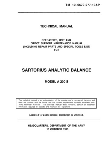
InstallationStandardequipped with two separatentiollastaInThe Aladdin Light Lift istemoReSafety Benefitsindependent locking systems tosecurely hold the chandelier. ForNo Access?maximum safety, electrical currentfixture is lowered. There's no riskAladdinhas the solution!of electrical shock whileAladdin Light Lift offers a remotecleaning or changing bulbs.mounting option that consists of ato the chandelier is automaticallydisconnected while theunique system of cables, brackets,and pulleys which are builtinto your light lift.The remote mounting optionis needed when no direct accessis available above the chandelier.Easy to InstallFeaturesThe Aladdin Light Lift is neatly tucked away in the areaabove the ceiling, so there's no visible indication of thesystem. Installation by a licensed electrician is simple,since the system uses existing wiring. And, once in place,the chandelier can be installed at floor level safely andeconomically, eliminating the need for scaffolding."The Original Light Lift System"8370 Wolf Lake Drive, Suite 112Memphis, Tennessee 38133Phone (901) 385-0456 Fax (901) LL700MAX. WEIGHT200 Lbs.300 Lbs.700 Lbs.STANDARD WATTAGE1560 watts*1560 watts*2200 watts**OPTIONAL WATTAGE2200 watt - 1 circuit maximum3300 watt - 2 circuit maximum4400 watt - 2 circuit maximumWARRANTY1 year warranty on componentsSLOPED CEILINGSAdapter AvailableRELAMPING CORD OPTIONA separate cord which allowsuser to relight chandelier atfloor levelSPECIAL ORDER MODELS1000 Lb. maximumWINCH CABLE LENGTH35' Standard65', 90' or 120' OptionalPATENTED SYSTEMMade in USA
Model Number ALL200 ALL700 ALL300 ALL1000Remote Mount OptionDirectional PulleysSloped Ceiling AdapterGreenfieldThis light lift is equipped with a 35' winchcable unless checked below: 65' 90' 120'This light lift is equipped with a 1,560 wattlight capacity unless checked below: 2200 watts 3300 watts 2 circuit 4400 watts 2 circuit SmartLift Controller Relamping Cord
TABLE OF CONTENTSWarnings and Safety Precautions .1-2Features and BenefitsEasy Installation and Safety .3Keyswitch .3SmartLift Controller .4Relamping Cord .4How to Determine Your Model .5-6SmartLift Controller Guide .7-8Standard Installation Guide .9Special Situations: Standard Installation .16Special InstallationsDome Ceilings .19Sloped Ceilings .20Remote Installation Guide .21Special Situations: Remote Installations .32SpecificationsModels ALL200 and ALL300 .35Models ALL700 and ALL1000 .36Troubleshooting .37-39Warranty Card .40
WARNINGS ANDSAFETY PRECAUTIONSThe following statements are warnings and safety precautions for the installation,operation, and maintenance of the Aladdin Light Lift. Closely follow the installationinstructions when installing the Aladdin Light Lift. Please contact technical support(877) 287-4601 with any questions or concerns regarding the following:WARNINGS AND SAFETY PRECAUTIONS1. The Aladdin Light Lift is designed for use in accessible locations only. See remoteinstallation guide for additional options.2. Do not exceed wattage capacity of lighting circuitry. Refer to the owner’s manual for exactcapacity of the light lift.3. The power source for the motor on the Aladdin Light Lift should be fed by a source otherthan the light switch leg.4. The Aladdin Light Lift must be mounted on a level plane in a standard installation. Thewinch cable should be plumb through the center of the top contact plate on the ceiling box.5. Never operate the Aladdin Light Lift without weight or tension on the winch cable.This can cause the cable to jump off the winch spool and get caught in the winch gears.Contact technical support toll free at (877) 287-4601 should this situation occur.6. Never extend the full length of winch cable from the Aladdin Light Lift. This couldcause the cable to become reversed on the winch. See Keyswitch operation tag andoperation instructions. Refer to the owner’s manual for winch cable length on theAladdin Light Lift. Contact technical toll free at (877) 287-4601 should this occur.7. Use the permanent screw collar loop furnished with the chandelier.8. Always make sure the dowel pin is flush in the nipple of the bottom contact plate. Thefixture coupler should be threaded over the dowel pin and hole at all times.9. Always disconnect power source from the Aladdin Light Lift when servicing orperforming maintenance.10. Never use a dimmer switch unless motor is wired on a separate circuit from lights.11. Always remove packing tape from the winch before operating the light lift.12. Always wait five seconds between running the Aladdin Light Lift in opposite directions.13. Only adjust length of chain to adjust chandelier elevation. Never cut or adjust thelength of winch cable.1
14. Never adjust the cone height on the bottom contact plate. This will interfere with theautomatic shutoff system.15. Never allow the chandelier’s canopy to make contact with the ceiling before the contactplates meet. This will cause a canopy sized hole in the ceiling.16. Always use the supplied thread lock where the fittings attach the chandelier to the bottomcontact plate.18. Do not stand or sit underneath the chandelier while operating the Aladdin Light Lift.19. In remote installations, make sure the winch cable is unobstructed between pulleys.20. In remote installations, make sure the winch cable travels straight to and from thepulley grooves for proper operation. Keeping the pulleys on the same plane is thebest way to insure cable alignment.21. Do not hang or swing from the Aladdin Light Lift winch cable.22. Never hang anything but a single stem or chain hung chandelier from the AladdinLight Lift.23. Do not hang more than one chandelier from the Aladdin Light Lift.24. Never use multiple Aladdin Light Lifts to hang one chandelier.25. Periodically inspect winch cable for frays or kinks. If a fray or kink is detected,contact technical support toll free at (877) 287-4601.26. Only use fittings, such as the dowel pin, nipples, and fixture couplers, supplied byAladdin Light Lift to hang the chandelier.27. Never alter the Aladdin Light Lift from its original state.28. Always turn the chandelier's lights off at the wall switch when operating the AladdinLight Lift.2WARNINGS AND SAFETY PRECAUTIONS17. Never install the Aladdin Light Lift where the ceiling height exceeds the existing length ofwinch cable. This could cause a reversed cable. The length of cable is marked on theAladdin Light Lift cover, in the owner’s guide, and on the outer shipping box. Seewarning and safety precaution number 6. Contact technical support toll free at(877) 287-4601 should a reversed cable situation occur.
FEATURESAND BENEFITSEasy to InstallThe Aladdin Light Lift is neatly tucked away in the area above the ceiling, leaving novisible indication of the system. Installation by a licensed electrician is simple, in bothnew construction and existing homes. And, once in place, the chandelier can beinstalled at floor level safely and economically.FEATURES AND BENEFITSDesigned for Years of Trouble-Free OperationThe Aladdin Light Lift is designed for years of trouble-free operation. The patentedsystem has been rigorously tested and uses the latest technology for electricalcomponents and its gearing mechanism. Even heavy chandeliers are no problem for aproperly sized Aladdin Light Lift.Safety BenefitsIndependently tested. UL and CUL Listed (ALL1000 Pending)Each model is equipped with two separate independent locking systems to securely holdthe chandelier. For maximum safety, electrical current to the chandelier is automaticallydisconnected while the chandelier is lowered. There is no risk of electrical shock whilecleaning or changing bulbs.WarrantyThe Aladdin Light Lift is backed by a full 1-year limitedwarranty on all parts and components.Just Turn the KeyThe Aladdin Light Lift comes with a special Keyswitchwhich can be conveniently installed in any new orexisting wall. The Keyswitch is child resistant andprevents accidental activation of the light lift. Thechandelier is lowered by simply inserting the key andturning the switch. Releasing the key stops thechandelier at the height you choose. It's that easy.*Standard on ALL200 and ALL300*Special Order on ALL700 and ALL10003
FEATURESAND BENEFITSSmartLift ControllerThe SmartLift Controller is designed to operate the Aladdin LightLift with touch pad controls. It can be programmed toautomatically stop at any desired height above the floor. Itautomatically shuts off at the ceiling without being programmed.*Standard on ALL700 and ALL1000*Special Order on ALL200 and ALL300FEATURES AND BENEFITSNo Access? Aladdin has the solution!Aladdin Light Lift offers a remote mountingoption that consists of a unique system ofcables, brackets, and pulleys which are builtinto the light lift.The remote mounting option is needed whenno direct access is available above thechandelier. This option MUST be orderedwith the light lift. Remote mount options ordirectional pulleys can not be added to astandard installation light lift.Relamping CordThe relamping cord is used to temporarilyrelight the chandelier at floor level.To operate: After lowering the chandelier tofloor level, unscrew one bulb. Remove the endcap and screw the metal chandelier base insidethe plastic tube down into the chandeliersocket. Plug the Relamping Cord into anextension cord and plug into a wall outlet.This will relight all the bulbs in thechandelier. The Relamping Cord is designedfor candelabra-base fixtures.Caution: This is a temporary relampingsource. Do not use this cord to permanentlylight a chandelier.4
HOW TO DETERMINEYOUR MODELThe following questions will assist you in determining which Aladdin Light Liftto order:1. How heavy is the chandelier that will be installed on the Aladdin Light Lift?HOW TO DETERMINE YOUR MODELAladdin Light Lift, Inc. offers four different models. They range from 200lbs to300lbs to 700lbs to 1000lbs. The 200lb is the model ALL200, the 300lb is themodel ALL300 and so on. If the chandelier weighs less than 200lbs, the ALL200 issufficient. If the chandelier weighs more than 200 lbs and less than 300 lbs, orderthe ALL300. If the chandelier weighs more than 300lbs, order the ALL700, etc.2. How high is the ceiling in the room where the chandelier will hang?The standard installation light lift winch cable length is 35 feet. If morewinch cable is needed due to ceiling height, Aladdin offers increments of65 feet, 90 feet, and 120 feet.3. How much wattage does the chandelier have?The ALL200 and ALL300 come standard with the capacity to handle 1560 watts.The ALL700 and ALL1000 come standard with the capacity to handle 2200 watts.Aladdin offers wattage upgrade packages of 2200, 3300 (2-circuit), and 4400(2-circuit) watts. Two circuit packages can not be used with remote options and cannot be added in the field.4. Can the Aladdin Light Lift be mounted directly above the chandelier?Standard light lifts are designed to be installed directly above the chandelier. Thisrequires a minimum of three feet of vertical access space. If this space is notavailable, the remote mount option must be ordered with the light lift.STANDARD INSTALLATION LIGHT LIFTS CAN NOT BE MODIFIEDTO REMOTE INSTALLATION LIGHT LIFTS IN THE FIELD.THE REMOTE MOUNT OPTION MUST BE ORDERED WITH THE LIGHT LIFT.A. REMOTE MOUNT OPTION: Includes: 65' winch cable, remote mountingbracket with pulley on top to mount on or between ceiling joists, a horizontal cablefeed from motor assembly, 25' of romex and limit switch wiring. The light liftmotor assembly can be mounted up to 25' away from the pulley above the chandelier.B. DIRECTIONAL PULLEYS: These are used to change the direction of thewinch cable-up or down-one pulley for each change. If the light lift motor unit willmount directly in line with where the chandelier hangs, a directional pulley isnot necessary. However, if the direction changes up or down, as in a sloped ceiling,a directional pulley is needed for each change.5
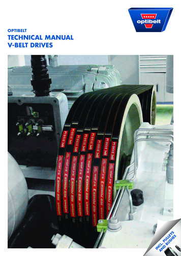
C. SLOPED CEILING ADAPTOR: Includes a threaded nipple, brass ball, andcanopy. This allows the canopy to rotate on the brass ball so the canopy can pullup at an angle on the sloped ceiling. (Can be added in the field)D. CONDUIT CUT TO MINIMUM: Order the remote light lift with conduitcut to minimum if the depth for the bracket and pulley on top is less than12 1/2 inches for the ALL200 or ALL300: less than 13 inches for the ALL700or ALL1000.REMOTE INSTALLATION MODEL NUMBER EXAMPLE:ALL200-RM-2DP-2200W-SLC. This means an order for a 200lb light lift with a remotemount option, two directional pulleys, a 2200 watt upgrade kit, and a SmartLift Controller.See the Remote Installation Guide for technical drawings.HOW TO DETERMINE YOUR MODELAutomatically lowers yourchandelier for easycleaning andbulb changing.6
SMARTLIFTCONTROLLER GUIDEHOME POSITION: Understanding the HOME POSITION is essential to operating andprogramming the SmartLift Controller. The HOME POSITION is when the light liftautomatically shuts itself off at the ceiling.NEW INSTALLATION:SMARTLIFT CONTROLLER GUIDE--Plug the controller into the low voltage control wire and make sure power is applied to thelight lift.--If the light lift is at the HOME POSITION, proceed to PROGRAMMING THE DOWNPOSITION.--If the light lift is NOT at the HOME POSITION, all of the lights will flash and the unit willbeep three times. To enable the controller, press the SET button until it beeps and the SETlight flashes. Now, press the UP button. The controller is enabled when it beeps and theREADY light turns green. The UP and DOWN lights will flash and it beeps. Press the UP orDOWN button to run the light lift depending on your installation needs. The controllerbecomes disabled after 90 seconds of inactivity.--When ready, press the UP button to run the light lift to the HOME POSITION.The controller can only be programmed from the HOME POSITION.PROGRAMMING THE DOWN POSITION:--The light lift must be at the HOME POSITION for programming.--Programming the controller’s ‘down position’ should not be performed until the chandelier isinstalled and final chain length is determined.--To program a ‘down position,’ first enable the controller. To enable the controller, press theSET button until it beeps and the SET light flashes. Now, press the UP button. The controlleris enabled when it beeps and the READY light turns green. The controller becomes disabledafter 90 seconds of inactivity.--Once enabled, press the DOWN button until the chandelier reaches the desired elevation.Press the SET button then press the DOWN button. The ‘down position’ is programmed whenit beeps and the DOWN light is on.--To return the light lift to the HOME POSITION press the AUTO button then the UPbutton. The light lift will run up automatically and shut off at the ceiling.--When the ‘down position’ is programmed, it will always be remembered: even if there is apower outage. If there is a power outage, run light lift to the HOME POSITION beforerunning it to the ‘down position.’7
--To clear the programmed ‘down position,’ press the DOWN button and the SET buttonsimultaneously until the DOWN light flashes. Press the DOWN button again and theprogrammed ‘down position’ is cleared with a beep.--Once the controller is programmed, use the NORMAL OPERATION section for future use.NORMAL OPERATION:--If controller is programmed, press the AUTO button then the DOWN button to run thelight lift to the ‘down position.’ Press the AUTO button then the UP button to return thelight lift to the HOME POSITION. Press the UP button to stop the lift from running downat any time. Press the DOWN button to stop the lift from running up at any time.--If the controller has not been programmed, press the DOWN button to run the light lift tothe desired elevation. Press the UP button to return the chandelier to the HOMEPOSITION.--Although the controller will disable after 90 seconds of inactivity, it may be necessary todisable it on your own. To do so, press the SET button until it beeps and the SET lightflashes. Now, press the UP button. The controller is disabled when it beeps and the READYlight goes out.OTHER IMPORTANT NOTES:--Never fully extend all of the winch cable from the light lift. This can cause a reversed cablesituation which can be hazardous. See the owner’s manual for cable length.--Never allow a child to operate an Aladdin Light Lift or SmartLift Controller.--Make sure the winch cable is plumb through the center of the ceiling box before runninglight lift to the HOME POSITION.--Contact Aladdin Light Lift’s technical support if you experience problems operating theSmartLift Controller. (877) 287-46018SMARTLIFT CONTROLLER GUIDE--To operate the light lift, first enable the controller. To enable the controller, press the SETbutton until it beeps and the SET light flashes. Now, press the UP button. The controller isenabled when it beeps and the READY light turns green. The controller becomes disabledafter 90 seconds of inactivity.
INSTALLATION GUIDE:STANDARD INSTALLATIONIf this installation guide is needed in Spanish or French,contact Aladdin Light Lift at (877) 287-4601.Always disconnect the power when servicing or performing maintenance to the light lift.Electricity can kill!STANDARD INSTALLATIONThis installation guide is for STANDARD INSTALLATION Aladdin Light Liftsthat mount in accessible locations directly above the chandelier. If the light liftcontains a remote mounting option, refer to the REMOTE INSTALLATION guide (page 21).ALL200 and ALL300ALL700 and ALL10009
GETTING STARTED:1. Details regarding light wattage capacity and weight capacity of the light lift are marked onthe inside cover of the owner’s manual.2. Study the ‘Warnings and Safety Precautions page’ in the owner’s manual.3. Read the installation instructions, study the drawings carefully, and study each partand step.4. Make sure all needed parts are present. The standard light lift unit consists ofchannel strut, chassis plate, winch, motor, control board, pulley, winch cable, ceiling box,bottom contact plate, temporary weight, conduit assembly, fixture coupler, and wiring. Thefollowing items should also be included in the parts bag and Keyswitch/SmartLiftController bag:A. #10 x 1-1/4" Pan Phillips-Wood ScrewsB. 3/16" x 1" Fender WashersSTANDARD INSTALLATIONC. fixture couplerD. jam nutE. screw collar ringF. thread lockG. Keyswitch assemblyorH. SmartLift Controller assemblyINSTALLATION TIPS: STANDARDa. Wire the lights and motor on separate circuits. The motor draws minimal amperage soa dedicated circuit is not necessary, but should be separate from the lights.b. The winch cable must be centered in the ceiling box. Check the cable’s position afterchandelier is installed.c. Never operate motor without tension on the winch cable.d. Use the permanent screw collar loop furnished with the chandelier.e. Light lifts being installed in commercial applications must use Greenfield for the linevoltage wiring. Remove the plastic cover if using in an air handling space.10
STANDARD INSTALLATIONf.Aladdin Light Lift motors must be installed in accessible locations. Remote mountingoptions can be used for installations where the motor can not be mounted directly abovethe chandelier.g. Never install the light lift in ceilings with heights that exceed the winch cable length.The cable length is marked on the inside cover of the owner’s manual.h. Never fully extend the winch cable from the light lift. If the light lift is continuouslyrun down, the cable can fully extend and start back up again reversing itself on the winch.This will cause the disc brake to be inoperative and possibly cause the fixture to fall.i. There are a few ways to tell if the winch cable is reversed. The ALL200 and ALL300leaves the factory with the cable rolling off of the top of the winch. The ALL700 andALL1000 leaves the factory with the cable rolling off of the bottom of the winch. Ifthe cable is opposite of this, the cable is reversed. Also, if the cable is reversed, the light liftwill not shut down properly when the chandelier gets to the ceiling. If the light liftdoesn’t make a consistent clicking or ratcheting sound while running up, the cable isreversed. Contact Aladdin Light Lift immediately if any of these situations occur.j. If the light lift is not operating properly, have a licensed electrician follow thetroubleshooting guide found in the owner’s manual. Most of the time, the problem canbe fixed by following the troubleshooting guide. If not, have an electrician contacttechnical support from the light lift in the attic with two jumper wires and a volt meter.Usually, the problem can be fixed over the phone. The toll free tech support line is(877) 287-4601.OPERATION TIPS: STANDARDa. Turn the chandelier off at the light switch when operating an Aladdin Light Lift.b. If the Keyswitch is used, hold the key to the right to run the light lift down. Let go of thekey when a desired elevation is reached. Turn and hold the key to the left to run the lightlift up. If installed correctly, the light lift will shut off automatically when it reaches theceiling. At this time it is safe to turn the chandelier back on.c. If using a SmartLift Controller, refer to the SmartLift Controller Guide in theowner’s manual. See page 7.d. Never fully extend the winch cable from the light lift. If the light lift is continuouslyrun down, the cable can fully extend and start back up again reversing itself on the winch.This will cause the disc brake to be inoperative and possibly cause the fixture to fall. Thecable length is marked on the inside of the owner’s manual.e. There are a few ways to tell if the winch cable is reversed. The ALL200 and ALL300leaves the factory with the cable rolling off of the top of the winch. The ALL700 andALL1000 leaves the factory with the cable rolling off of the bottom of the winch. Ifthe cable is opposite of this, the cable is reversed. Also, if the cable is reversed, the light liftwill not shut down properly when the chandelier gets to the ceiling. If the light liftdoesn’t make a consistent clicking or ratcheting sound while running up, the cable isreversed. Contact Aladdin Light Lift immediately if any of these situations occur.f. If the light lift is not operating properly, have a licensed electrician follow thetroubleshooting guide found in the owner’s manual. Most of the time, the light lift canbe fixed by following the troubleshooting guide. If not, have an electrician contacttechnical support from the light lift in the attic with two jumper wires and a volt meter.Most of the time, the light lift can be fixed over the phone. Our toll free tech supportline is (877) 287-4601.11
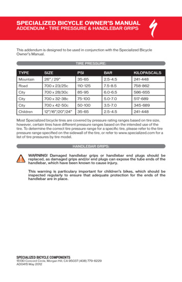
STEP 1-STANDARD INSTALLATION1. Take the light lift out of the box and remove the cover.2. Determine where the light lift will sit on the joists directly above where the chandelier will hang.3. If joist interferes where the chandelier will hang, see SPECIAL SITUATIONS:STANDARD INSTALLATION ‘B’ (page 17).Diagram ASTEP 2-STANDARD INSTALLATIONIMPORTANT: The ceiling box should not touch the inside of the 4 1/2" hole in the ceiling. Theceiling box does not support any weight of the chandelier. The tension is on the winch cable. Theconduit assembly can be adjusted later to accommodate for different canopy depths. The set screw inthe conduit coupler must be secure for the automatic shutoff system to work. Use the 3/32" Allenwrench for adjustments.3/8" Channel StrutAdjustment BoltsWood Screws& Fender WashersDiagram BWood Screws& Fender Washers3/8" Channel StrutAdjustment Bolts12STANDARD INSTALLATION1. If an existing ceiling box is present,it must be removed. Only use theceiling box provided with thelight lift.2. Cut a 4 1/2" hole in theceiling for the ceiling box. If youTop Conduit Connectorremoved an existing ceiling box,the hole may need to be enlarged.Conduit3. Attach the top of the conduitAdjustmentConduit Coupler (3/32" Allen wrench)assembly into the conduitSet Screwconnector and tighten the setBottom Conduit Connectorscrew. The connector is4" Ceiling Boxunderneath the pulley on thelight lift.4. Attach the bottom of the conduit assembly to the ceiling box and tighten the set screw.
STANDARD INSTALLATIONSTEP 3-STANDARD INSTALLATION1. Mount the light lift LEVEL, spanning across the ceiling joists directly above where thechandelier will hang. The pulley assembly on the light lift designates where the winchcable will exit though the ceiling box.2. The light lift has bolts that hold it to the channel strut. These bolts may be loosened forchannel strut adjustments. Do not forget to retighten the bolts if this adjustment was made.3. Secure the channel strut to the ceiling joists using the wood screws and washers in the partsbag supplied with the light lift.4. Loosen the set screw on the 1/2" end of the conduit coupler using the 3/32" Allenwrench. Adjust the ceiling box up or down and retighten the set screw to make it flushwith the ceiling. This is a good starting point before hanging the chandelier.Note: The conduit assembly is made up of a 3/4" and 1/2" conduit heldtogether by a conduit coupler. The two pieces of conduit are telescopic.5. If the conduit is either too long or too short after adjusting, see SPECIALSITUATIONS: STANDARD INSTALLATION ‘C’ (page 17).6. Just because the light lift is mounted level, does not mean the winch cable is hangingthrough the center of the ceiling box. From the floor level, check the cable’s position inthe ceiling box. It should hang through the center of the top contact plate which isattached to the ceiling box. If the cable is not centered, the light lift will not shut offproperly when the chandelier reaches the ceiling. Use flat washers to shim one side or theother of the light lift’s channel strut until cable hangs through the center of the ceilingbox. Check cable position again, later, when chandelier is hung.STEP 4-STANDARD INSTALLATIONDiagram C12 gauge Light Neutral1. Wire the motor switch in the square box 12 gauge Light Hotwith 110V house wiring. The 14 gaugeGroundwiring in the square box is for the motor.This circuit does not have to be dedicatedbut must be separate from the light switchleg. The motor draws 1 amp on theALL200, ALL300 and ALL1000 andLIGHTdraws 2.5 amps on the ALL700.2. Wire the light switch in the square boxwith the 110V light switch leg. The 12gauge wiring in the square box is for thelights. A two circuit light package willrequire two hot leads and one neutral.3. If using a dimmer switch, wire it in linewith the light switch leg. Any dimmer canbe used with the light lift as long as themotor feed is kept separate from thelight switch leg.Hot Light SwitchLeg 110VIMPORTANT: Keep the neutral wiresseparate in the square box.Neutral LightSwitch Leg 110V1314 gauge Motor Neutral14 gauge Motor HotMOTOR110V House HotFor Motor110V House NeutralFor Motor
STEP 5-STANDARD INSTALLATIONDiagram DSTEP 6-STANDARD INSTALLATION1. After testing the light lift, plug the low voltage control wire back onto the control board andreattach the light lift’s cover.2. Run the 50’ low voltage control wire to a single gang box for the Keyswitch or optionalSmartLift Controller. This can be on the floor level or on a landing. The chandelier mustbe visible from this location.3. If a Keyswitch is being used, attach it to the cover plate using the supplied nut. Plug theKeyswitch or SmartLift Controller to the control wire that was pulled through the singlegang box. Use the supplied cover plate screws to attach Keyswitch or SmartLift Controllerto the gang box.4. If using a Keyswitch, test the light lift in both directions. First turn the key to the right to rundown a few inches. Then turn left to run up until the light lift turns itself off at the ceiling. Allow2 seconds after operating the light lift in one direction before operating in the other.5. If using a SmartLift Controller, see the SmartLift Controller Guide to run the light lift tothe HOME POSITION. See page 7.IMPORTANT: If the light lift installation takes place before the ceiling has been painted, leave thelight lift in the "UP" position. This will prevent paint from getting on the top contact plate. Apainted contact plate will not allow the chandelier to light.STEP 7-STANDARD INSTALLATION1. Using either the Keyswitch or the SmartLift Controller, run the light lift down to a desiredelevation to hang the chandelier. Remember, if a SmartLift Controller is being used, thecontroller must be enabled before running the light lift. See the SmartLift ControllerGuide in the owner’s manual on page 7.14STANDARD INSTALLATION1. Make sure there is tension on the winch cable. The fivepound weight provided with the lift is sufficient for this test.2.
operation, and maintenance of the Aladdin Light Lift. Closely follow the installation instructions when installing the Aladdin Light Lift. Please contact technical support (877) 287-4601 with any questions or concerns regarding the following: 1. The Aladdin Light Lift is designed for use in accessible locations only. See remote