Transcription
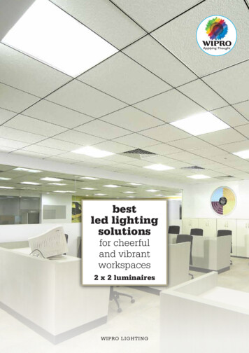
USG Exterior Ceiling SystemsSYSTEMS GUIDEThe Calyx, Royal Botanical Gardens, Sydney, AustraliaCelebration Metal Panels, Custom Size and FinishArchitect: PTW Architects, Photo: Sam Grant
USG EXTERIOR CEILING SYSTEMSSYSTEMS GUIDEFor decades, USG exterior ceiling systems have been utilized in a widevariety of exterior applications because they not only satisfy stringentperformance requirements and design criteria but also provide beautyand durability.Introduction4SYSTEMS OVERVIEWExterior Ceiling ApplicationsPerformance SelectorExterior CeilingApplications9LINEAR METAL CEILING SYSTEMSParaline IIParaline Plus25METAL PANEL CEILING SYSTEMSCelebration Snap-InCelebration Torsion SpringOther Considerations39LAY-IN PANELS45CONTINOUS CEILINGS47FinishesUSG Sheetrock Brand Gypsum Lay-In Panels (GLIP)USG Sheetrock Brand Drywall with USG Drywall Suspension System (DWSS)Compression PostsSeismic Perimeter ApplicationsFor More InformationTechnical Service: 800.USG.4YOUWebsite: usg.comUSG EXTERIOR CEILING SYSTEMS2
USG EXTERIOR CEILING SYSTEMSSYSTEMS GUIDECeiling Product Data SheetsLINEAR METAL CEILING SYSTEMSParaline IIParaline PlusMETAL PANEL CEILING SYSTEMSCelebration Snap-InCelebration Torsion SpringLAY-IN PANELSUSG Sheetrock Brand Gypsum Lay-In Panels (GLIP)CONTINOUS CEILINGSUSG Sheetrock Brand Drywall with USG Drywall Suspension System (DWSS)USG EXTERIOR CEILING SYSTEMS3
SYSTEMS OVERVIEWExterior Ceiling ApplicationsINTRODUCTIONUSG provides six systems for use in exterior environments that are not directly exposed tothe weather, such as under soffits, parking garages, covered entrances, or drive-throughs: Paraline II Linear Metal Ceiling System1 Paraline Plus Linear Metal Ceiling System Celebration Snap-In Metal Panel Ceiling System Celebration Torsion Spring Metal Panel Ceiling System ZXLA with USG Sheetrock Lay-In Ceiling Panel USG Drywall Suspension SystemThese ceiling systems combine traditional modules, elegant linear pans, or metal panelswith a specially engineered suspension system to create dynamic ceilings featuring clean,contemporary planes.This guide covers flat ceilings attached to perimeter walls on all sides. installed per ASTMC636. For other installations including sloped or curved ceilings consult USG architecturalRepresentative.These guidelines outline the design considerations, test results, and construction details forthe installation of each USG exterior ceiling system. USG exterior assemblies were testedper UL 580, UL 1897, TAS 202, and TAS 203, and listed in PEI Evaluation Report, PER-12055.For more information about UL Standards, please visit www.UL.com.For more information about Florida Building Code Testing Application Standards (TAS),please visit www.floridabuilding.org.1The Paraline II closed-reveal linear metal ceiling is the Paraline system appropriate for exterior ceiling applications.USG EXTERIOR CEILING SYSTEMS4
SYSTEMS OVERVIEWExterior Ceiling ApplicationsWIND DESIGN NOTESMiles Per Hour (mph) versus Pounds Per Square Foot (psf)ASCE 7-16, Minimum Design Loads for Buildings and Other Structures, American Societyof Civil Engineers/Structural Engineering Institute (ASCE/SEI), contains a formula thatconverts wind speed into static pressure. The formula is a comprehensive approach toinclude factors such as height or location of the building or directionality of wind loadsaffecting the structure expressed as:qz 0.00256 KzKztKdV2qz velocity pressure evaluated at height z above the ground (psf)Kz velocity pressure exposure coefficientKzt topographic factorKd wind directionality factorV basic wind speed (mph)All the test results presented in this guide were achieved by measuring the maximumpressure that the system can withstand. The formula above provides guidance on how toestimate the wind speed correlating to the particular pressure. Because the factors (Kz, Kzt,Kd) are project specific, they were conservatively estimated to be equal to one. Therefore,the simplified formula to estimate wind speed based on given pressures is as follows:V qz/0.00256Wind load provisions of ASCE 7-16 are recognized in the 2018 International ResidentialCode (IRC) and the 2018 International Building Code (IBC). The information presented iscorrect to the best of our knowledge at the date of issuance. Because codes continue toevolve, check with a local official prior to designing and installing a ceiling system. Otherrestrictions and exemptions may apply.WIND PRESSURETEST METHODSUSG exterior assemblies were tested for both uplift (positive) and downward (negative)pressures. The positive values represent uplift capacity and the negative values representdownward capacity. Testing for both positive and negative pressures offers a morecomplete assessment of the performance of USG assemblies. It also allows USG to evaluateand certify the comparative resistance of USG assemblies to both positive and negativepressures. With the publication of this thorough wind load assessment, design professionalscan be assured USG exterior assemblies satisfy the most stringent performancerequirements and design criteria.USG EXTERIOR CEILING SYSTEMS5
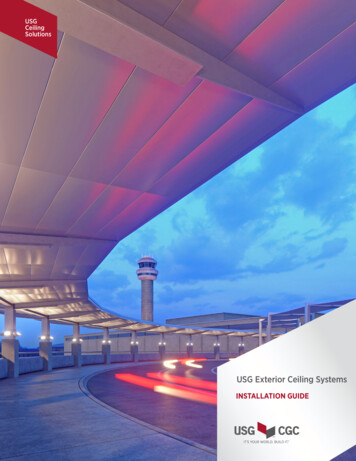
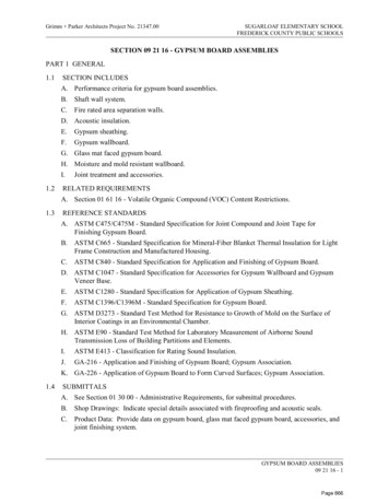
PRODUCT SELECTORLinear Metal Ceiling SystemsPARALINE II(See page 9)12-ga.hangerwireCompression post sized by others.Must meet loading and plenumheight requirements.PRODUCT PERFORMANCE RANGESPressure psf(kPa)UpDown46 to 102(2.20 to 4.88)-106(-5.08)Windspeedmph (Kph)135 to 200(217 to 322)STANDARD PAINTED METALSsymmetricalcarrierFlat White Silver Satin050002hanger reinforcement clipParaline II pan One part system - pans with integral closed reveal. Pans can be removed for plenum access. 3-1/4" wide pans, 3/4" integral closed reveal, 12' long pans. NOA issued by Miami Dade County.PARALINE PLUS(See page 9)12-ga.hangerwireCompression post sized by others.Must meet loading and plenumheight requirements.PRODUCT PERFORMANCE RANGESPressure psf(kPa)UpWindspeedmph (Kph)Down30 to 127-25 to -3898 to 222(1.44 to 6.08) (-1.20 to -1.82) (158 to 357)STANDARD PAINTED METALSParalock Plusmain teeSnap-Loc InsertFlat White Silver Satin050002ANODIZED METALSParaline Plus pan 2 part system - pans with Snap-Loc inserts toclose reveal between pans. Snap-Loc inserts and pans can be removedfor plenum access. 3" & 7" wide, 1" reveal, 12' long pans. Approved for installation in seismic categoryC, D, E, & F. Notice of Acceptance (NOA) issued by MiamiDade County.SatinChromePM614WOOD rry3468LightCherry3469Maple3470Red Oak3471Walnut3472USG EXTERIOR CEILING SYSTEMS6
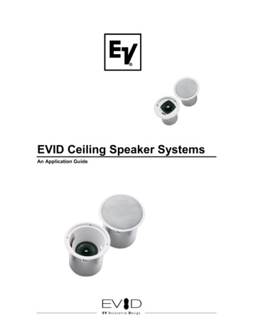
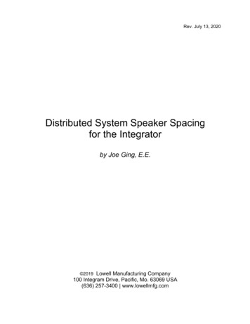
PRODUCT SELECTORMetal Panel Ceiling SystemsCELEBRATION SNAP-INUSG Donn Brand Fineline DXF acoustical suspension systemPRODUCT PERFORMANCE RANGESPressure psf(kPa)(See page 25)UpDownWindspeedmph (Kph)30 to 102-25 to -7098 to 222(1.44 to 4.88) (-1.20 to -3.35) (158 to 321)RotateCelebration TMRemovalToolP/N 209216USG Celebration panelremoval toolUSG Celebration panels snap in place Aluminum panels provide a monolithic appearance. Easy Installation into standard USG Donn BrandFineline "DXFEVH" Acoustical Suspension System. Available panel sizes: 2' x 2', 2' x 4', 2' x 6', 2' x 8',4' X 4', 30" X 30" & 30" X 60".STANDARDPAINTED METALSFlat White Silver Satin050002 NOA issued by Miami Dade County.CELEBRATION TORSION SPRING(WITH HEAVY DUTY ZXLA )(See page 25)SatinChromePM614(2' x 2' only)WOOD rry3468LightCherry3469Maple3470Red Oak3471Walnut3472 Downward panel access is excellent for shallowplenum areas. Approved for installation in seismic category C, D, E, & F.ANODIZEDMETALSPRODUCT PERFORMANCE RANGESPressure psf(kPa)UpDown15 to 133(0.72 to 6.37)-13.3(-0.64)STANDARDPAINTED METALS Aluminum panels provide a monolithic appearance. Spring clip design provides superior panel alignment. Full 90-degree swing-down motion. Downward panel access is excellent for shallowplenum areas. Available panel sizes: 2' x 2', 2' x 4', 2' x 6', 2' x 8'& 4' x4'. Approved for installation in seismic categoryC, D, E, & F. NOA issued by Miami Dade County.Windspeedmph (Kph)77 to 228(124 to 367)ANODIZEDMETALSFlat White Silver Satin050002SatinChromePM614(2' x 2' only)WOOD rry3468LightCherry3469Maple3470Red Oak3471Walnut3472USG EXTERIOR CEILING SYSTEMS7
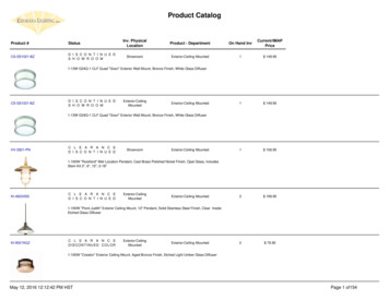
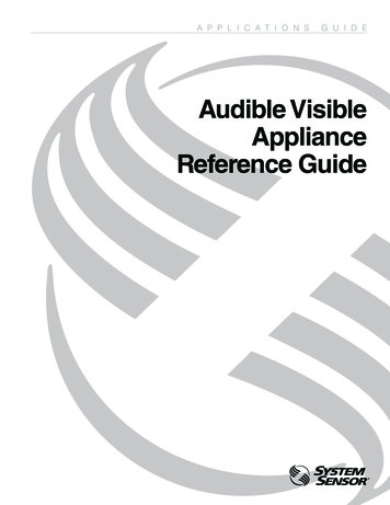
PRODUCT SELECTORLay-In PanelsUSG SHEETROCK BRANDLAY-IN PANELS {GLIP)(WITH HEAVY DUTY ZXLA )(See page 39)PRODUCT PERFORMANCE RANGESPressure psf(kPa)UpDown21 to 85(1.01 to 4.07)-13(-0.62)Windspeedmph (Kph)90 to 182(145 to 293)STANDARD PAINTED METALSFlat White050 Washable and scrubbable finish-impact andscratch resistant. Recommended for garage applications. Available panel sizes: 2' x 2' & 2' x 4'. Approved for installation in seismic categoryC, D, E, & F.Continuous CeilingsDRYWALLSUSPENSION SYSTEM(See page 39)CDPRODUCT PERFORMANCE RANGESPressure psf(kPa)Compressionpost sized byothers. Mustmeet loading andplenum heightrequirements.Uphanger wire15 to 90(0.72 to 4.31)main teecross teeDownWindspeedmph (Kph)77 to 188(124 to 302)FIELD PAINTEDAB Must be finished for exterior application. Seedocumment WB2451 for addtional information. Apply a synthetic-type direct-applied finishsystem in accordance with finish manufacturer'srecommendations. Approved for installation in seismic categoryC, D, E, & F NOA issued by Miami Dade CountyUSG EXTERIOR CEILING SYSTEMS8
LINEAR METAL CEILING SYSTEMSPARALINE II AND PARALINE PLUSTechnical DataMain TeePARALINE IIPARALINE PLUSSymmetricalCarrierParalock PlusAll AcceptablePanel Sizes(Inch)Main TeeSpacing(Inch)Cross TeeSpacing(Inch)CompressionPost /4483, 73, 7Maximum Load Rating(psf)EquivalentWind Speedmph (kph)Upliftpsf (kPa)Downwardpsf (kPa)UL 18971102 (4.88)-106 (-5.08) 200 (322)24UL 580290 (4.31)188 (302)N/A24UL 1897146 (2.20)135 (217)482424UL 580230 (1.44)98 (158)482424UL 1897155 (2.63)147 (237)13242424UL 1897127 (6.08)-38 (-1.82)222 (357)7242424UL 18971127 (6.08)-25 (-1.20)222 (357)3 and 7242424UL 580290 (4.31)188 (302)3242430UL 580260 (2.87)153 (246)3 and 7242424Miami Dade NOA 75 (3.59)TAS 202 & 2033-35 (-1.68)171 (275)Factor of safety of 1.17 is includedFactor of safety of 1.5 for 30 psf; 1.3 for 60 psf; 1.17 for 90 psf is included per test standard3Factor of safety of 1.5 is included per test standard12USG EXTERIOR CEILING SYSTEMS9
LINEAR METAL CEILING SYSTEMSPARALINE II AND PARALINE PLUSWIND RESISTANCEUSG Paraline ceiling systems may be used for protected exterior applications not directlyexposed to the weather. The Paraline II and Paraline Plus systems have been tested forwind load resistance. The two units of measure commonly used are miles per hour (mph) andpounds per square foot (psf), equated by the methods in ASCE 7, Minimum Design Loads forBuildings and Other Structures, American Society of Civil Engineers/Structural EngineeringInstitute (ASCE/SEI).1Limitations: The Paraline finish is not UV-resistant; therefore, these ceiling systems shouldnot be installed where direct exposure to sun or weather will occur, such as fascias or facades.These ceiling systems are not suitable for areas subject to high concentrations of acid rain.Indirect exposure to severe environmental conditions may shorten the lifespan of theseproducts. The specific design of exterior ceiling installations requires the review and approvalof the architect or engineer of record. For more information refer to Paraline Linear MetalCeiling Systems IC463.TECHNICAL DATA The wind pressure is presented in accordance with applicable test standards. The compression posts used for the tests were minimum 1-5/8", 20-gauge steel studs.(maximum length of 24") For Paraline II tests, EMT conduit with USG top and bottom clips were used.GUIDELINES The building structure from which the Paraline system is suspended, as well as hanger wireand compression post attachment connections must be capable of withstanding the designloads connections. For further information on the compression post, see page 49 Other materials can be used for compression posts, provided the capacity and attachmentconnections are approved for use by a structural engineer of record. The architect’s details must cover the design and location of expansion joints and meet allapplicable building code requirements.PANEL SIZESThe Paraline II and Paraline Plus systems presented in this guide can accommodate 3-1/4"wide pans for Paraline II and 3" & 7" wide Paraline Plus pan sizes.1The system shall comply with local wind load requirements. The engineer of record shall determine the finalrecommendation for the design wind pressure requirements of each project.For more information about Paraline linear metal ceiling systems, visit usg.comUSG EXTERIOR CEILING SYSTEMS10
LINEAR METAL CEILING SYSTEMSPARALINE IISystem ComponentsPERIMETER MOLDINGU-2-3/3211/8"2 3/32"7ACCESSORIES/8"U-2-3/32 Hold-Down Clip/ "11 322 3/32"/4"3USG EXTERIOR CEILING SYSTEMS11
LINEAR METAL CEILING SYSTEMSPARALINE IIApplication DetailsGENERAL LAYOUT148"48"Paraline pansplice staggeredsymmetrical carrierhangerwires andcompressionpostcarrier spliceParaline pancompressionposthangerreinforcementclip24"max. 12" from walltrim channelfinished wallor soffit1The product layout and spacing will vary based on the load rating and uplift class.Refer to the technical data and associated reference pages for details.USG SYMMETRICALCARRIER RUNstructureCompression postsized by others.Must meet loadingand plenum heightrequirementshangerreinforcementcliptop clip(mechanically fastened)spring clipcompressionpost adaptertop clip(mechanically fastened)spring cliphangerreinforcement clipsymmetrical carrierCOMPRESSIONPOST DETAILmaximum 48" o.c.compression postsand hanger wires12-ga. hanger wirecompressionpost adapterhanger reinforcement clipsymmetrical carrierUSG EXTERIOR CEILING SYSTEMS12
LINEAR METAL CEILING SYSTEMSPARALINE IIApplication DetailsWALL INTERSECTIONPans Perpendicular to WallCompression postsized by others.Must meet loadingand plenum heightrequirementshangerreinforcement clipParaline II pan12" maximumsymmetricalcarrierPans Parallel to WallCompression postsized by others.Must meet loadingand plenum heightrequirements12-ga. hanger wire12" maximumsymmetricalcarrier#7 tek screwat each carrierlocationFasten moldingto framing at16" o.c.U-2-3/32 perimetermolding andhold-down clipParaline II panhangerreinforcement clipU-2-3/32 perimetermolding andhold-down clipUSG EXTERIOR CEILING SYSTEMS13
LINEAR METAL CEILING SYSTEMSPARALINE IIUL 189746 psfMain Tees: 48 in. o.c.Compression Posts: 24 in. o.c.Hanger & Compression PostParaline Symmetrical Carrier24" o.c.12" max.48" o.c.12"max.Paraline II Assembly12-ga.hangerwireCompression post sized by others.Must meet loading and plenumheight requirements.Compression post sized by others.Must meet loading and plenumheight requirements.12-ga. hanger er reinforcement clipParaline II panParaline II pansymmetricalcarrierUSG EXTERIOR CEILING SYSTEMS14
LINEAR METAL CEILING SYSTEMSPARALINE IIUL 580Class 90Main Tees: 24 in. o.c.Compression Posts: 24 in. o.c.Hanger & Compression PostParaline Symmetrical Carrier24" o.c.12" max.24" o.c.12"max.Paraline II Assembly12-ga.hangerwireCompression post sized by others.Must meet loading and plenumheight requirements.12-ga. hanger wireCompression post sized byothers. Must meet loading andplenum height rrierParaline II panhanger reinforcement clipParaline II pansymmetricalcarrierUSG EXTERIOR CEILING SYSTEMS15
LINEAR METAL CEILING SYSTEMSPARALINE IIUL 1897106 psf (Downward)Main Tees: 24 in. o.c.Compression Posts: 24 in. o.c.Hanger & Compression PostParaline Symmetrical Carrier24" o.c.12" max.24" o.c.12"max.Paraline II Assembly12-ga.hangerwireCompression post sized by others.Must meet loading and plenumheight requirements.12-ga. hanger wireCompression post sized byothers. Must meet loading andplenum height rrierParaline II panhanger reinforcement clipParaline II pansymmetricalcarrierUSG EXTERIOR CEILING SYSTEMS16
LINEAR METAL CEILING SYSTEMSPARALINE PLUSSystem ComponentsPERIMETER MOLDINGU-2-5/811/8"2 5/8"/"7 8ACCESSORIESU-2-5/8 Hold-Down Clip/ "11 322 5/8"/4"3USG EXTERIOR CEILING SYSTEMS17
LINEAR METAL CEILING SYSTEMSPARALINE PLUSApplication DetailsGENERAL LAYOUT148"48"Paraline Pluspan splice staggeredParalock Plus main teeParaline pancompressionposthanger wires24"max. 12" from wallU 2-5/8perimetermoldingfinished wall or soffit1The product layout and spacing will vary based on the load rating and uplift class.Refer to the technical data and associated reference pages for details.PARALOCKCARRIER RUNstructureCompression postsized by others.Must meet loadingand plenum heightrequirements.top clip(mechanically fastened)spring cliptop clip(mechanicallyfastened)spring clipParalock Plusmain teeParalock Plus main teePOST DETAIL12-ga. hanger wiremaximum 48" o.c.compression postsand hanger wiresCompression postsized by others.12-ga. hanger wireMust meet loadingand plenum heightrequirements.Compression postsized by others.Must meet loadingand plenum heightrequirements.Paralock Plus Main teeUSG EXTERIOR CEILING SYSTEMS18
LINEAR METAL CEILING SYSTEMSPARALINE PLUSApplication DetailsWALL INTERSECTIONPans Perpendicular to WallCompression postsized by others.Must meet loadingand plenum heightrequirements.12" maximumcross teePans Parallel to WallCompression postsized by others.Must meet loadingand plenum heightrequirements.12-ga. hanger wire12" maximumParalockPlusmain teeParalock Plusmain teeSnap-Loc InsertParaline Plus panU-2-5/8 perimetermolding and U-2-5/8hold-down clipSnap-Loc InsertParaline Plus panU-2-5/8 perimetermolding and U-2-5/8hold-down clipUSG EXTERIOR CEILING SYSTEMS19
LINEAR METAL CEILING SYSTEMSPARALINE PLUSUL 580Class 30UL 189755 psfMain Tees: 48 in. o.c.Compression Posts: 24 in. o.c.Cross Tees: 24 in o.c.Hanger & Compression PostParalock Plus Main TeeZXLA424 (48 in. Cross Tee)24" o.c.12" max.48" o.c.12"max.Paraline Plus Assembly12-ga.hangerwireCompression post sized by others.Must meet loading and plenumheight requirements.12-ga. hanger wireCompression post sized by others.Must meet loading and plenumheight requirements.U 2-5/8perimetermoldingParalock Plusmain teeSnap-Loc InsertParaline Plus panParaline Plus panZXLA 4ft. cross teeSnap-Loc InsertParalock Plus main teeUSG EXTERIOR CEILING SYSTEMS20
LINEAR METAL CEILING SYSTEMSPARALINE PLUSUL 580Class 60Main Tees: 24 in. o.c.Compression Posts: 30 in. o.c.Cross Tees: 24 in o.c.Hanger & Compression PostParalock Plus Main TeeZXLA224 (24 in. Cross Tee)24" o.c.30" o.c.12" max.24" o.c.12"max.Paraline Plus Assembly12-ga.hangerwireCompression post sized by others.Must meet loading and plenumheight requirements.12-ga. hanger wireCompression post sized by others.Must meet loading and plenumheight requirements.U 2-5/8perimetermoldingParalock Plusmain teeSnap-Loc InsertParaline Plus panParaline Plus panZXLA 2ft. cross teeSnap-Loc InsertParalock Plus main teeUSG EXTERIOR CEILING SYSTEMS21
LINEAR METAL CEILING SYSTEMSPARALINE PLUSUL 58090 psfUL 1897102 psfMiami-Dade NOA No. 15-12223.05171 mphMain Tees: 24 in. o.c.Compression Posts: 24 in. o.c.Cross Tees: 24 in o.c.Hanger & Compression PostParalock Plus Main TeeZXLA224 (24 in. Cross Tee)24" o.c.12" max.24" o.c.12"max.Paraline Plus Assembly12-ga.hangerwireCompression post sized by others.Must meet loading and plenumheight requirements.12-ga. hanger wireCompression post sized byothers. Must meet loading andplenum height requirements.U 2-5/8perimetermoldingParalock Plusmain teeSnap-Loc InsertParaline Plus panParaline Plus panZXLA 2ft. cross teeSnap-Loc InsertParalock Plus main teeUSG EXTERIOR CEILING SYSTEMS22
LINEAR METAL CEILING SYSTEMSPARALINE PLUSUL 189717 psf (Downward Load)Main Tees: 24 in. o.c.Compression Posts: 24 in. o.c.Cross Tees: 24 in o.c.Hanger & Compression PostParalock Plus Main TeeZXLA224 (24 in. Cross Tee)24" o.c.12" max.24" o.c.12"max.Paraline Plus Assembly12-ga.hangerwireCompression post sized by others.Must meet loading and plenumheight requirements.12-ga. hanger wireCompression post sized byothers. Must meet loading andplenum height requirements.U 2-5/8perimetermoldingParalock Plusmain teeSnap-Loc InsertParaline Plus panParaline Plus panZXLA 2ft. cross teeSnap-Loc InsertParalock Plus main teeUSG EXTERIOR CEILING SYSTEMS23
PAGE 24 INTENTIONALLY LEFT BLANK.
METAL PANEL CEILING SYSTEMSCELEBRATION SNAP-INCELEBRATION TORSION SPRINGTechnical DataMain TeeCELEBRATION SNAP-INDXFEVH2924DXFEVH2930CELEBRATION TORSION SPRINGZXLA26All AcceptablePanel Sizes(Inch)Main TeeSpacing(Inch)Cross TeeSpacing(Inch)CompressionPost Spacing(Inch)TestStandard12 x 24, 12 x 48 4824 x 24, 24 x 48242424 x 24, 24 x 48 2424 x 72, 24 x 962424 x 24, 24 x 48 2424 x 72, 24 x 96Maximum Load Rating(psf)EquivalentWind Speedmph (kph)Upliftpsf (kPa)Downwardpsf (kPa)UL 1897130 (1.44)-25 (-1.20)24UL 580290 (4.31)188 (302)2424UL 18971102 (4.88)200 (321)24 x 24, 24 x 48 242424Miami Dade NOA 80 (3.83)TAS 202 & 2033-70 (-3.35)176 (283)30 x 30, 30 x 60 303030UL 1897172 (3.45)-51 (-2.44)141 (227)30 x 30, 30 x 60 3030302UL 58060 (2.87)153 (246)24 x 24, 24 x 48 242424UL 580290 (4.31)188 (302)24 x 24, 24 x 48 242424UL 1897133 (6.37)228 (367)24 x 24242424Miami Dade NOA 73.3 (3.51)TAS 202 & 2033-13.3 (-0.64) 170 (274)24 x 72722448/24UL 580230 (1.44)98 (158)48 x 484824482UL 58015 (0.72)77 (124)24 x 48, 24 x 96 482424UL 580230 (1.44)98 (158)198 (158)Factor of safety of 1.17 is includedFactor of safety of 1.5 for 30 psf; 1.3 for 60 psf; 1.17 for 90 psf is included per test standard3Factor of safety of 1.5 is included per test standard12USG EXTERIOR CEILING SYSTEMS25
METAL PANEL CEILING SYSTEMSCELEBRATION SNAP-INCELEBRATION TORSION SPRINGWIND RESISTANCEBoth USG Celebration Snap-In and Torsion Spring metal panel ceiling systems may be usedfor protected exterior applications not directly exposed to the weather. Celebration SnapIn and Torsion Spring metal panel ceiling systems have been tested for wind load resistance.The two units of measure commonly used are miles per hour (mph) and pounds per squarefoot (psf), equated by methods in ASCE 7, Minimum Design Loads for Buildings and OtherStructures, American Society of Civil Engineers/Structural Engineering Institute (ASCE/SEI).1Limitations: The Celebration finish is not UV-resistant; therefore, the Celebration Snap-Inand Torsion Spring metal panel ceiling systems should not be installed where direct exposureto sun or weather will occur, such as fascias or facades. These systems are not suitable forareas subject to high concentrations of acid rain. Indirect exposure to severe environmentalconditions may shorten the lifespan of these products. The specific design of exterior ceilinginstallations requires the review and approval of the architect or engineer of record. For moreinformation refer to Celebration and Panz Metal Ceiling Systems, IC415.TECHNICAL DATA The wind pressure is presented in accordance with applicable test standards. The compression posts used for the tests were minimum 1-5/8", 20-gauge steel studs.(maximum length of 24")GUIDELINES The building structure from which the Celebration Snap-In or Torsion Spring ceiling systemis suspended and spaced, as well as the hanger wire, compression posts, or studs used inthe assembly, must be capable of withstanding the design loads. For further information onthe compression posts see page 49. Heavy duty main tees shall be used. Other materials can be used for compression posts provided the capacity and attachmentconnections are approved for use by a structural engineer of record. The architect’s details must cover the design and location of expansion joints and meet allapplicable building code requirements. Arrowhead Reveal Spacers (CA1) shall be installed.PANEL SIZESThe Celebration Snap-In systems presented in this guide can accommodate all availablepanel sizes. The performance values are not limited to a particular panel size. All availablepanel sizes will meet the performance values presented.The Celebration Torsion Spring systems presented in this guide can accommodate thefollowing panel sizes: 2ft.x2ft., 2ft.x4ft., 2ft.x6ft., 2ft.x8ft., and 4ft.x4ft.1The system shall comply with local wind load requirements. The engineer of record shall determine the finalrecommendation for the design wind pressure requirements of each project.For more information about Paraline linear metal ceiling systems, visit usg.comUSG EXTERIOR CEILING SYSTEMS26
METAL PANEL CEILING SYSTEMSCELEBRATION SNAP-INSystem ComponentsPERIMETER MOLDINGU-2-3/3211/8"2 3/32"/8"7ACCESSORIESU-2-3/32 Hold-Down Clip/32"112 3/32"/4"3CA1 Arrowhead Reveal Spacer1/4"1/4"USG EXTERIOR CEILING SYSTEMS27
METAL PANEL CEILING SYSTEMSCELEBRATION SNAP-INUL 189725 psf (Downward Load)Main Tees: 48 in. o.c.Cross Tees: 24 in o.c.Compression Posts: 24 in. o.c.Hanger & Compression PostDXFEVH2924(Heavy Duty Main Tee)DXFEV429N (48 in. Cross Tee)DXFEV229 (24 in. Cross Tee)Note: Celebration Snap-In panelscannot be installed across a maintee and a 4 ft. cross tee.24" o.c.12" max.48" o.c.12"max.PERIMETER CONDITIONS12" max.12-ga. hanger wireCompression post sized byothers. Must meet loading andplenum height requirements.U-2-3/32 moldingDXFEVH Fineline main teearrowhead spacer forcut perimeter panelsinto first reveal rowCelebration Snap-Inperimeter panelU-2-3/32 holddown clip min. 2per perimeter panelNote: A fastener attachment through the top leg of the molding into the tee bulb is required.USG EXTERIOR CEILING SYSTEMS28
METAL PANEL CEILING SYSTEMSCELEBRATION SNAP-INUL 580Class 90UL 1897102 psfMiami-Dade NOA No. 15-12223.04176 mphMain Tees: 24 in. o.c.Cross Tees: 24 in o.c.Compression Posts: 24 in. o.c.Hanger & Compression PostDXFEVH2924(Heavy Duty Main Tee)DXFEV229 (24 in. Cross Tee)Note: Celebration Snap-In panelscannot be installed across amain tee.24" o.c.12" max.24" o.c.12"max.PERIMETER CONDITIONS12" max.12-ga. hanger wireCompression post sized byothers. Must meet loading andplenum height requirements.U-2-3/32 moldingDXFEVH Fineline main teearrowhead spacer forcut perimeter panelsinto first reveal rowCelebration Snap-Inperimeter panelU-2-3/32 holddown clip min. 2per perimeter panelUSG EXTERIOR CEILING SYSTEMS29
METAL PANEL CEILING SYSTEMSCELEBRATION SNAP-INUL 189751 psfMain Tees: 30 in. o.c.Cross Tees: 30 in o.c.Compression Posts: 30 in. o.c.Hanger & Compression PostDXFEVH2930(Heavy Duty Main Tee)DXFEV30 (30 in. Cross Tee)11Special OrderNote: Celebration Snap-In panelscannot be installed across amain tee.30" o.c.15" max.30" o.c.15"max.PERIMETER CONDITIONS12" max.12-ga. hanger wireCompression post sized byothers. Must meet loading andplenum height requirements.U-2-3/32 moldingDXFEVH Fineline main teearrowhead spacer forcut perimeter panelsinto first reveal rowCelebration Snap-Inperimeter panelU-2-3/32 holddown clip min. 2per perimeter panelUSG EXTERIOR CEILING SYSTEMS30
METAL PANEL CEILING SYSTEMSCELEBRATION SNAP-INUL 189768 psfUL 580Class 60Main Tees: 30 in. o.c.Cross Tees: 30 in o.c.Compression Posts: 30 in. o.c.Hanger & Compression PostDXFEVH2930(Heavy Duty Main Tee)DXFEV30 (30 in. Cross Tee)11Special OrderNote: Celebration Snap-In panelscannot be installed across amain tee.30" o.c.15" max.30" o.c.15"max.PERIMETER CONDITIONS12" max.12-ga. hanger wireCompression post sized byothers. Must meet loading andplenum height requirements.U-2-3/32 moldingDXFEVH Fineline main teearrowhead spacer forcut perimeter panelsinto first reveal rowCelebration Snap-Inperimeter panelU-2-3/32 holddown clip min. 2per perimeter panelUSG EXTERIOR CEILING SYSTEMS31
METAL PANEL CEILING SYSTEMSCELEBRATION TORSION SPRINGSystem ComponentsPERIMETER MOLDINGOption 1Two Layers of M7Zmain tee orcross teeM7Z wall molding7/8"1/8" rivet(2 per tee end)7/8"1 5/8"T-15 hold down clipM7Z wall moldingpanelOption 2CTS15AL Perimeter Moldingmain tee orcross tee7/8"1/8" rivet(2 per tee end)2 1/2"CTS15AL perimetermolding1 5/8"T-15 hold down clip7/8"ACCESSORIESpanelT15 Hold-Down Clip11/32"1 9/16"3/4"USG EXTERIOR CEILING SYSTEMS32
METAL PANEL CEILING SYSTEMSCELEBRATION TORSION SPRINGUL 580Class 90UL 1897133 psfMiami-Dade NOA No. 16-0404.02170 mphMain Tees: 24 in. o.c.Cross Tees: 24 in o.c.Compression Posts: 24 in. o.c.Panel Sizes: 2 ft. x 2 ft. and2 ft. x 4 ft.Hanger & Compression PostZXLA26 (Heavy Duty Main Tee)TSCT22ZXA (24 in. Cross Tee)24" o.c.12" max.24" o.c.12"max.COMPRESSIONPOST DETAILSmain tee1 5/8"1 1/8"(4) #7 tekscrewsCompression post sizedby others. Must meetloading and plenumheight requirements.(Steel stud shown)main tee(4) #7 tekscrewscross teePlan Viewhanger wirecross teeSide ViewUSG EXTERIOR CEILING SYSTEMS33
METAL PANEL CEILING SYSTEMSCELEBRATION TORSION SPRINGUL 580Class 30Main Tees: 48 in. o.c.Cross Tees: 24 in o.c.Compression Posts: 48 in. o.c.Panel Sizes: 2 ft. x 4 ft. and2 ft. x 8 ft.Hanger & Compression PostZXLA26 (Heavy Duty Main Tee)TSCT44ZXA (48 in. Cross Tee)24" o.c.12" max.48" o.c.12"max.COMPRESSIONPOST DETAILSmain tee1 5/8"1 1/8"(4) #7 tekscrewsCompression post sizedby others. Must meetloading and plenumheight requirements.(Steel stud shown)main tee(4) #7 tekscrewscross teePlan Viewhanger wirecross teeSide ViewUSG EXTERIOR CEILING SYSTEMS34
METAL PANEL CEILING SYSTEMSCELEBRATION TORSION SPRINGUL 580Class 30Main Tees: 72 in. o.c.Cross Tees: 24 in o.c.Compression Posts: 24 in. o.c.Panel Size: 2 ft. x 6 ft.Hanger & Compression PostZXLA26 (Heavy Duty Main Tee)TSCT66ZXA (72 in. Cross Tee)ZXLA224 (24 in. Cross Tee)24" o.c.12" max.72"12"max.24"COMPRESSIONPOST DETAILSmain tee1 5/8"1 1/8"(4) #7 tekscrewsCompression post sizedby others. Must meetloading and plenumheight requirements.(Steel stud shown)main tee(4) #
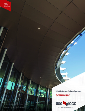
Light Bamboo 3466 Dark Cherry 3468 Light Cherry 3469 Maple 3470 Red Oak 3471 Walnut 3472 PRODUCT PERFORMANCE RANGES Pressure psf (kPa) Wind speed mph (Kph) Up Down 30 to 102 (1.44 to 4.88)-25 to -70 (-1.20 to -3.35) 98 to 222 (158 to 321) Metal Panel Ceiling Systems PRODUCT S