Transcription
Autodesk Revit 2017 MEPFundamentals SDCP U B L I C AT I O N SBetter Textbooks. Lower Prices.www.SDCpublications.com
Visit the following websites to learn more about this book:Powered by TCPDF (www.tcpdf.org)
ChapterBasic Sketching and ModifyToolsBasic sketching, selecting, and modifying tools are the foundation of working withall types of elements in the Autodesk Revit software, including componentssuch as air terminals, plumbing fixtures, and electrical devices. Using these toolswith drawing aids helps you to place and modify elements to create accuratebuilding models.Learning Objectives in this Chapter Ease the placement of elements by incorporating drawing aids, such as alignment lines,temporary dimensions, and snaps. Place Reference Planes as temporary guide lines. Insert components such as mechanical equipment, plumbing fixtures, and electrical devices. Use techniques to select and filter groups of elements. Modify elements using a contextual tab, Properties, temporary dimensions, and controls. Move, copy, rotate, and mirror elements and create array copies in linear and radial patterns. 2016, ASCENT - Center for Technical Knowledge 2–1
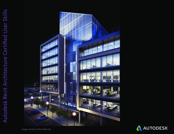
Autodesk Revit 2017 MEP Fundamentals2.1 Using General SketchingToolsWhen you start a command, the contextual tab on the ribbon,Options Bar, and Properties palette enable you to set up featuresfor each new element you are placing in the project. As you startmodeling, several features called drawing aids display, as shownin Figure 2–1. They help you to create designs quickly andaccurately.Contextual tabOptions BarDrawing aidsProperties paletteFigure 2–1 When you model ducts, pipes, cable trays, or conduits orplace elements such as air terminals, lighting fixtures orplumbing fixtures, you first need to: Drawing Aids2–2Select a type from the Type Selector.Set information in the Options Bar.Check the Contextual tab for other options.As soon as you start sketching or placing elements, severaldrawing aids display, including: Alignment lines Temporary dimensions Snaps Connectors 2016, ASCENT - Center for Technical Knowledge
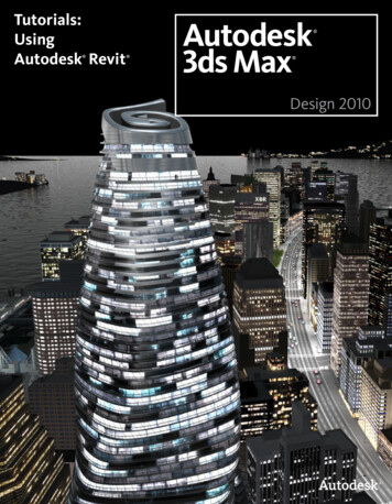
Basic Sketching and Modify ToolsThese aids are available with most drawing and manymodification commands, as shown in Figure 2–2.Alignment LinesSnapsTemporary DimensionsFigure 2–2Alignment lines display as soon as you move the cursor overnearby elements. They help keep lines horizontal, vertical, or ata specified angle. They also line up with the implied intersectionsof walls and other elements. Hold Shift to force the alignments to be orthogonal (90degree angles only).Temporary dimensions display to help place elements at thecorrect length, angle and location. You can type in the dimension and then move the cursoruntil you see the dimension you want, or you can placethe element and then modify the dimension as required.The length and angle increments shown vary dependingon how far in or out the view is zoomed.For Imperial measurements (feet and inches), thesoftware uses a default of feet. For example, when youtype 4 and press Enter , it assumes 4’-0”. For a distancesuch as 4’-6”, you can type any of the following: 4’-6”, 4’6,4-6, or 4 6 (the numbers separated by a space). Toindicate distances less than one foot, type the inch mark(”) after the distance, or enter 0, a space, and then thedistance. 2016, ASCENT - Center for Technical Knowledge 2–3
Autodesk Revit 2017 MEP FundamentalsHint: Temporary Dimensions and Permanent DimensionsTemporary dimensions disappear as soon as you finish addingelements. If you want to make them permanent, select thecontrol shown in Figure 2–3.Figure 2–3Snaps are key points that help you reference existing elementsto exact points when drawing, as shown in Figure 2–4.Figure 2–4 When you move the cursor over an element, the snapsymbol displays. Each snap location type displays with adifferent symbolConnectors (MEP only) work similar to snaps, but have moreintelligence about the size, system, and flow of items (e.g., ducts,pipes, and electrical connections). For example, connectorsautomatically add fittings to ducts, such as the elbow, transition,and tee shown in Figure 2–5.Fittings controlled by connectorsFigure 2–52–4 2016, ASCENT - Center for Technical Knowledge
Basic Sketching and Modify ToolsHint: Snap Settings and OverridesIn the Manage tab Settings panel, click(Snaps) to openthe Snaps dialog box, which is shown in Figure 2–6. The Snapsdialog box enables you to set which snap points are active, andset the dimension increments displayed for temporarydimensions (both linear and angular).Figure 2–6 Keyboard shortcuts for each snap can be used to overridethe automatic snapping. Temporary overrides only affect asingle pick, but can be very helpful when there are snapsnearby other than the one you want to use. 2016, ASCENT - Center for Technical Knowledge 2–5
Autodesk Revit 2017 MEP FundamentalsReferenceHint: Measuring ToolsWhen modifying a model, it is useful to know the distancebetween elements. This can be done with temporarydimensions, or more frequently, by using the measuring toolsfound in the Quick Access Toolbar or on the Modify tab Measure panel, as shown in Figure 2–7.Figure 2–7Planes (Measure Between Two References): Select twoelements and the measurement displays. (Measure Along An Element): Select the edge of alinear element and the total length displays.As you develop designs in the Autodesk Revit software, thereare times when you need lines to help you define certainlocations. You can draw reference planes (which display asdashed green lines) and snap to them whenever you need to lineup elements. For the example shown in Figure 2–8, the lightingfixtures in the reflected ceiling plan are placed using referenceplanes. To insert a reference plane, in the Architecture, Structure, orSystems tab Work Plane panel, clicktype RP.2–6(Ref Plane) or 2016, ASCENT - Center for Technical Knowledge
Basic Sketching and Modify ToolsFigure 2–8 Reference planes display in associated views because theyare infinite planes, and not just lines. You can name Reference planes by clicking on Click toname and typing in the text box, as shown in Figure 2–9.2017Figure 2–9 If you sketch a reference pane in Sketch Mode (used withfloors and similar elements), it does not display once thesketch is finished. Reference planes can have different line styles if they havebeen defined in the project. In Properties, select a style fromthe Subcategory list. 2016, ASCENT - Center for Technical Knowledge 2–7
Autodesk Revit 2017 MEP Fundamentals2.2 Inserting ComponentsComponents (also known as families) are full 3D elements thatcan be placed at appropriate locations and heights, and whichinteract with the building elements around them. For example, alighting fixture can be designed to be hosted by a face (such as awall or ceiling), or to stand alone by itself on the floor, as shownin Figure sedfamilyComponents arelocated in family fileswith the extension .RFA.For example, acomponent familynamed Wall Sconce.rfacan contain severaltypes and sizes.Figure 2–10Most components are inserted using specific tools including:Exact steps for insertingspecific components arecovered later in thisguide.Air terminalMechanical EquipmentPlumbing FixtureSprinklerElectrical EquipmentDevices (Data, Fire Alarm, Switches, etc.)Lighting Fixtures2–8 2016, ASCENT - Center for Technical Knowledge
Basic Sketching and Modify Tools Take time to get to know the components that come with theAutodesk Revit MEP software. Their most critical content arethe connectors, as you see in for a piece of mechanicalequipment in Figure 2–11.Figure 2–11 Connectors often contain options to create systems and drawducts and pipes when you right-click on them.How To: Insert Components1. Start the appropriate command.2. In the Type Selector, select the type/size you want to use, asshown in Figure 2–12.Figure 2–12 2016, ASCENT - Center for Technical Knowledge 2–9
Autodesk Revit 2017 MEP Fundamentals3. In the command-specific contextual tab Tag panel, click(Tag on Placement) to toggle this option on or off.4. Proceed as follows, based on the type of component used:If thecomponent is.Then.Not hostedSet the Level and Offset in Properties, as shown inFigure 2–13.Wall hostedSet the Elevation in Properties, as shown inFigure 2–14.Face hostedSelect the appropriate method in the contextual tab Placement panel, as shown in Figure 2–15. Vertical Faces include walls and columns. Faces include ceilings, beams, and roofs. Work Planes can be set to levels, faces, and namedreference planes.Figure 2–13Figure 2–14Figure 2–155. Place the component in the model. A fast way to add components that match those already inyour project is to select one, right-click on it, and selectCreate Similar, as shown in Figure 2–16. This starts theappropriate command with the same type selected.Figure 2–162–10 2016, ASCENT - Center for Technical Knowledge
Basic Sketching and Modify ToolsHint: Work PlanesA Work Plane is the surface you sketch on or extrude from. In aplan view, the Work Plane is automatically parallel to the level.In an elevation or 3D view, you must specify the Work Planebefore you start sketchingHow To: Select a Work Plane1. Start a command that requires a work plane or, in theArchitecture tab Work Plane panel, click(Set).2. In the Work Plane dialog box, select one of the followingoptions: Name: Select an existing level, grid, or named referenceplane (as shown in Figure 2–17) and then click OK.Figure 2–17 Pick a plane: Click OK and select a plane in the view,such as a wall face. Ensure the entire plane ishighlighted before you select it. Pick a line and use the work plane it was sketchedin: Click OK and select a model line, such as a roomseparation line.If you are in a view in which the sketch cannot be created, theGo To View dialog box opens. Select one of the views and clickOpen View. 2016, ASCENT - Center for Technical Knowledge 2–11
Autodesk Revit 2017 MEP FundamentalsLoadingComponentsYou can load additional families into a project. In the contextualtab Mode panel, click(Load Family) and then navigate tothe appropriate location for your company. The Autodesk Revitlibrary has components available in the following folders: CableTray, Conduit, Duct, Electrical, Fire Protection, Lighting,Mechanical, Pipe, and Plumbing.How To: Load a Family1. In the related contextual tab Mode panel or Insert tab Loadfrom Library panel, click(Load Family).2. In the Load Family dialog box, locate the folder that containsthe family or families you want to load, as shown inFigure 2–18.Figure 2–183. Select the family or families you want to load. You can hold Ctrl to select multiple families.4. Click Open.2–12 2016, ASCENT - Center for Technical Knowledge
Basic Sketching and Modify ToolsHint: Matching PropertiesYou can select an existing wall and use it to assign the wall typeand instance properties to other walls by using the Match Typecommand. This command also works with all elements thathave types.1. In the Modify tab Clipboard panel, click(Match Type) ortype MA. The cursor changes to an arrow with a cleanpaintbrush.2. Select the source element that you want all of the others tomatch. The paintbrush changes to look as if it has beendipped in black paint as shown in Figure 2–19.Figure 2–193. To select more than one element, in the Modify Match Typetab Multiple panel, click(Select Multiple). You can thenuse windows, crossings, Ctrl , and Shift to create aselection set of elements to change.4. Select the elements that you want to change. For multipleselections, clickselection.(Finish) to apply the type to the Click in an empty space in the project to empty the brush sothat you can repeat the command with a different element. Elements to be matched must be of the same type (e.g., allwalls, all doors, etc.). 2016, ASCENT - Center for Technical Knowledge 2–13
Autodesk Revit 2017 MEP FundamentalsPractice 2aInsert ComponentsPractice Objectives Load and Insert components. Use drawing aids. Add and name a reference plan. Select a work plane.Estimated time forcompletion: 10 minutesMechanicalIn this practice you will insert a variety of MEP fixtures, includingair terminals, plumbing fixtures and lighting fixtures, as shown inFigure 2–20. You will use various drawing aids to help you placethe fixtures appropriately.PlumbingElectricalFigure 2–20Task 1 - Insert air terminals.1. In the practice files Basics folder, openSimple-Building-Start.rvt.2. In the Project Browser, expand the Mechanical HVAC Floor Plans node. The 1 - Mech view is highlighted, and youare in a Mechanical floor plan.3. In the Systems tab HVAC panel, click(Air Terminal).4. In Properties, note that the default selection is a SupplyDiffuser and that the Level is Level 1. Set the Offset to 9’-0".5. Click near the center of room Lab 101, as shown inFigure 2–21.2–14 2016, ASCENT - Center for Technical Knowledge
Basic Sketching and Modify ToolsFigure 2–216. While still in the Air Terminal command, in the Type Selector,change the Type to Return Diffuser: 24 x 24 Face 12 x 12Connection and set the Offset to 9’-0".7. Click to place the component in the lower left corner of roomLab 101.8. In the Systems tab Mechanical panel, clickEquipment.)(Mechanical9. In the Type Selector, select Boiler: Standard.10. In the Mech/Elec Room, move the cursor near the outsidewall. Note that the boiler automatically aligns to the wall, asshown in Figure 2–22.Figure 2–2211. Click to place the component.12. Save the project. 2016, ASCENT - Center for Technical Knowledge 2–15
Autodesk Revit 2017 MEP FundamentalsTask 2 - Load and place plumbing fixtures.1. In the Project Browser, expand the Plumbing Plumbing Floor Plans node and double-click to open the 1 - Plumbingview. The air terminals are automatically toggled off becauseyou are in a plumbing view, but the boiler is still displayedbecause Mechanical Equipment is typically toggled on.2. In the Systems tab Plumbing & Piping panel, click(Plumbing Fixture).3. In the Type Selector, select one of the wall-mounted waterclosets.4. Click along one of the walls to place the fixture, as shown inFigure 2–23.Figure 2–235. Return to the Type Selector and review the list. Note thatthere are sinks, but no lavatories.6. In the Modify Place Plumbing Fixture tab Mode panel, click(Load Family).7. In the Load Family dialog box, the Autodesk Revit familylibrary automatically displays. Navigate to the Plumbing MEP Fixtures Lavatories folder and select Lavatory Oval.rfa, as shown in Figure 2–24.Figure 2–242–16 2016, ASCENT - Center for Technical Knowledge
Basic Sketching and Modify Tools8. Click Open.9. In the Type Selector, select Lavatory - Oval: 25"x20" Public.10. Place the lavatory against the wall across from the watercloset.11. Click(Modify) and select the new fixture. Drag it up ordown until it meets with the alignment line of the WC, asshown in Figure 2–25.Figure 2–2512. Click in space to release the selection.13. Save the project.Task 3 - Place a lighting fixture and switch.1. In the Project Browser, expand the Electrical Lighting Ceiling Plans node and double-click on 1 - Ceiling Elecview to open it. Ensure that you are opening the Ceiling Plan so that theceiling grids display.None of the previous elements that you have addeddisplay.2. In the Systems tab Electrical panel, clickFixture).(Lighting3. In the Type Selector, select Plain recessed LightingFixture: 2x4 - 277.4. In the Modify Place Fixture tab Placement panel, click(Place on Face). 2016, ASCENT - Center for Technical Knowledge 2–17
Autodesk Revit 2017 MEP Fundamentals5. Move the cursor over the grid. The light snaps to the gridlines, as shown in Figure 2–26.6. Press Spacebar to rotate the fixture. Click to place twofixtures in the room, as shown in Figure 2–27.Figure 2–26Figure 2–277. Open the Electrical Lighting Floor Plans 1 - Lighting view.The light fixtures display in this view although you are seeinga plan view.8. In the Systems tab Electrical panel, expand the Devicedrop-down list and select(Lighting).9. In the Type Selector, select Lighting Switches: Single Pole.10. In Properties, note that the Elevation is set to 4’-0", astandard height for switches.11. Place the switch to the left of the door. It displays only as asymbol.12. Click(Modify) to end the command.13. Save the project.2–18 2016, ASCENT - Center for Technical Knowledge
Basic Sketching and Modify Tools2.3 Selecting and EditingElementsBuilding design projects typically involve extensive changes tothe model. The Autodesk Revit software was designed to makesuch changes quickly and efficiently. You can change an elementusing the methods shown in Figure 2–28, and described below:Type SelectorContextual TabPropertiesControls andconnectorsTemporary dimensionsFigure 2–28 Type Selector enables you to specify a different type. This isfrequently used to change the size and/or style of theelements. Properties enables you to modify the information(parameters) associated with the selected elements. Temporary dimensions enable you to change the element’sdimensions or position. The contextual tab in the ribbon contains the Modifycommands and element-specific tools. Controls enable you to drag, flip, lock, and rotate the element. 2016, ASCENT - Center for Technical Knowledge 2–19
Autodesk Revit 2017 MEP Fundamentals Connectors control how related elements attach to anotherwith intelligence about size, needed fittings, and systeminformation. (MEP only) Shape handles (not shown) enable you to drag elements tomodify their height or length. To delete an element, select it and press Delete , right-clickand select Delete, or in the Modify panel, click(Delete).Working with Controls and ConnectorsWhen you select an element, various controls and connectorsdisplay depending on the element and view. Using controls, youcan change an elements length or location, and flip or rotatesome elements. MEP connectors also provide information aboutattachments and enable you to add related elements, as shownfor creating pipe from a pipe accessory in Figure 2–29.Figure 2–29 2–20If you hover the cursor over the control or connector, a tooltipdisplays showing its function. 2016, ASCENT - Center for Technical Knowledge
Basic Sketching and Modify ToolsHint: Editing Temporary DimensionsTemporary dimensions automatically link to the closest wall. Tochange the location, you can drag the Witness Line control (asshown in Figure 2–30) to connect to a new reference. You canalso click on the control to toggle between justifications in thewall.Before - connected tocenterline of wallAfter - connected toedge of wallFigure 2–30 The new location of a temporary dimension for an elementis remembered as long as you are in the same session ofthe software. 2016, ASCENT - Center for Technical Knowledge 2–21
Autodesk Revit 2017 MEP FundamentalsSelectingMultipleElements Once you have selected at least one element, hold Ctrl and select another item to add it to a selection set. To remove an element from a selection set, hold Shift andselect the element. If you click and drag the cursor to window around elements,you have two selection options, as shown in Figure 2–31. Ifyou drag from left to right, you only select the elementscompletely inside the window. If you drag from right to left,you select elements both inside and crossing the window.Window: Left to RightCrossing: Right to LeftFigure 2–31 If several elements are on or near each other, press Tab tocycle through them before you click. If there are elementsthat might be linked to each other, such as ductwork,pressing Tab selects the chain of elements. Press Ctrl Left Arrow to reselect the previous selectionset. You can also right-click in the drawing window withnothing selected and select Select Previous. To select all elements of a specific type, right-click on anelement and select Select All Instances Visible in View orIn Entire Project, as shown in Figure 2–32.You do no have toselect an element, justhover over the one youwant to select.Figure 2–322–22 2016, ASCENT - Center for Technical Knowledge
Basic Sketching and Modify ToolsHint: Selection OptionsYou can control how the software selects specific elements in aproject by toggling Selection Options on and off on the StatusBar, as shown in Figure 2–33. Alternatively, in any tab on theribbon, expand the Select panel’s title and select the option.Figure 2–33 Select links: When toggled on, you can selected linkeddrawings or Autodesk Revit models. When it is toggled offyou cannot select them when using Modify or Move. Select underlay elements: When toggled on, you canselect underlay elements. When toggled off, you cannotselect them when using Modify or Move. Select pinned elements: When toggled on, you canselected pinned elements. When toggled off, you cannotselect them when using Modify or Move. Select elements by face: When toggled on you canselect elements (such as the floors or walls in an elevation)by selecting the interior face or selecting an edge. Whentoggled off, you can only select elements by selecting anedge. Drag elements on selection: When toggled on, youcan hover over an element, select it, and drag it to a newlocation. When toggled off, the Crossing or Box select modestarts when you press and drag, even if you are on top of anelement. Once elements have been selected they can stillbe dragged to a new location. 2016, ASCENT - Center for Technical Knowledge 2–23
Autodesk Revit 2017 MEP FundamentalsFilteringSelection SetsWhen multiple element categories are selected, the Multi-Selectcontextual tab opens in the ribbon. This gives you access to all ofthe Modify tools, and the Filter command. The Filter commandenables you to specify the types of elements to select. Forexample, you might only want to select lighting fixtures, asshown in Figure 2–34.Figure 2–34How To: Filter a Selection Set1. Select everything in the required area.2. in the Modify Multi-Select tab Selection panel, or in theStatus Bar, click(Filter). The Filter dialog box opens, asshown in Figure 2–35.The Filter dialog boxdisplays all types ofelements in the originalselection.Figure 2–352–24 2016, ASCENT - Center for Technical Knowledge
Basic Sketching and Modify Tools3. Click Check None to clear all of the options or Check All toselect all of the options. You can also select or clearindividual categories as required.4. Click OK. The selection set is now limited to the elementsyou specified. In the Status Bar, the number of elements selected displaysbeside the Filter icon, as shown in Figure 2–36. You can alsosee the number of selected elements in the Propertiespalette.Figure 2–36 Clicking the Filter icon in the Status Bar also opens the Filterdialog box. 2016, ASCENT - Center for Technical Knowledge 2–25
Autodesk Revit 2017 MEP FundamentalsPractice 2bSelect and Edit ElementsPractice Objectives Use a variety of selection methods. Use temporary dimensions and connectors to modify the location ofelements.Estimated time forcompletion: 10 minutesIn this practice you will select lighting fixtures and change thetype (as shown in Figure 2–37), as well as test a variety ofselection methods and filters. You will then use connectors tomodify the location of an air terminal and use Create Similar toadd additional components. You will also modify the height of theair terminals in Properties.Figure 2–37Task 1 - Use a variety of selection methods.1. In the practice files Basics folder, openSimple-Building-Edit.rvt. It opens in the 1 - Lighting view.2. Select one of the light fixtures. The connectors and controlsare displayed.3. Hold Ctrl and select the other fixture. The connectors nolonger display, but you can still modify the fixture type.2–26 2016, ASCENT - Center for Technical Knowledge
Basic Sketching and Modify Tools4. In the Type Selector, change the type to Plain RecessedLighting Fixture: 1x4 - 277. Both fixtures change, as shownin Figure 2–38.Figure 2–385. Click away from any elements to clear the selection.6. Open the Mechical HVAC Floor Plans 1 - Mech view.7. Draw a window from left to right around some of theelements, similar to that shown in Figure 2–39.Figure 2–39 2016, ASCENT - Center for Technical Knowledge 2–27
Autodesk Revit 2017 MEP Fundamentals8. Note that only the elements completely inside the selectionwindow are selected.9. Click to clear the selection.10. Draw a crossing window (i.e., from right to left) around thesame area, as shown in Figure 2–40. Note that any elementsthat the window touches are included in the selection,including the linked architectural model.You can also toggle(Select Links) in theStatus Bar to keep thelink from being selected.Figure 2–4011. Hold Shift and select the edge of the architectural model.This removes the element from the selection set.12. In the Status Bar, note the number of items that are selectedand click(Filter).13. In the Filter dialog box, view the categories and clear thecheck from Air Terminals.14. Click OK. Only the room tags are still selected.15. Press Esc . The elements are no longer selected.16. Select one of the room tags. Right-click and select Select AllInstances Visible in View. All of the tags are selected.17. Click 2–28(Modify). The elements are no longer selected.Remember these selection methods as you start working inthe projects. 2016, ASCENT - Center for Technical Knowledge
Basic Sketching and Modify ToolsTask 2 - Modify elements using controls and properties.1. Continue working in the 1 - Mech view.2. Select, click and drag the supply air terminal to a newlocation using the alignment lines referencing the return airterminal.3. Right-click on the control and look at the variety of optionsyou can use, as shown in Figure 2–41.Figure 2–414. In the shortcut menu, select Create Similar. This starts theAir Terminal command using that type. Place two more airterminals in the same room, using alignment lines to placethem.5. Click(Modify) and select all three of the supply airterminals. Note the information in Properties. The Offset isset to 0’-0" above Level 1.6. Hold Ctrl and select the return air terminal. The Level andOffset are available to change, although two different types ofcomponents are selected. 2016, ASCENT - Center for Technical Knowledge 2–29
Autodesk Revit 2017 MEP Fundamentals7. Change the Offset to 8’-0" and click Apply. The offset for allof the air terminals is updated, as shown in Figure 2–42.Figure 2–428. Click away from any elements to clear the selection.9. Save the project.2–30 2016, ASCENT - Center for Technical Knowledge
Basic Sketching and Modify Tools2.4 Working with Basic ModifyToolsThe Autodesk Revit software contains controls and temporarydimensions that enable you to edit elements. Additionalmodifying tools can be used with individual elements or anyselection of elements. They are found in the Modify tab Modifypanel, as shown in Figure 2–43, and in contextual tabs.Figure 2–43Movingand CopyingElements The Move, Copy, Rotate, Mirror, and Array commands arecovered in this topic. Other tools are covered later. For most modify commands, you can either select theelements and start the command, or start the command,select the elements, and press Enter to finish the selectionand move to the next step in the command.The Move and Copy commands enable you to select theelement(s) and move or copy them from one place to another.You can use alignment lines, temporary dimensions, and snapsto help place the elements, as shown in Figure 2–44.Figure 2–44 2016, ASCENT - Center for Technical Knowledge 2–31
Autodesk Revit 2017 MEP FundamentalsHint: NudgeNudge enables you to move elements in short increments.When elements are selected, you can press one of the fourarrow keys to move the element in that direction. The distancethe element moves depends on how far in or out you arezoomed.How To: Move or Copy Elements1. Select the elements you want to move or copy.You can also use theshortcut for Move, MVor for Copy, CO.2. In the Modify panel, click(Move) or(Copy). Adashed boundary box displays around the selected elements.3. Select a move start point on or near the element.4. Select a second point. Use alignment lines and temporarydimensions to help place the elements.5. When you are finished, you can start another modifycommand using the elements that remain selected, or switchback to Modify to end the command. If you start the Move command and hold Ctrl , the elementsare copied.Move/Copy Elements OptionsThe Move and Copy commands have several options thatdisplay in the Options Bar, as shown in Figure 2–45.Figure 2–452–32ConstrainRestricts the movement of the cursor to horizontal orvertical, or along the axis of an item that is at an angle. Thiskeeps you from selecting a point at an angle by mistake.Constrain is off by default.Disjoin(Move only)Breaks any connections between the elements beingmoved and other elements. If Disjoin is on, the elementsmove separately. If it is off, the connected elements alsomove or stretch. Disjoin is off by default.Multiple(Copy only)Enables you to make multiple copies of one selection.Multiple is off by default. 2016, ASCENT - Center for Technical Knowledge
Basic Sketching and Modify Tools These commands only work in the current view, not betweenviews or projects. To copy between views or projects, in theModify tab Clipboard panel, use(Cut to the Clipboard), and 2017(Copy to Clipboard),(Paste from Clipboard).Many tools such as Move, Copy, and the clipboardcommands can be used in perspective views.Hint: Pinning ElementsIf you do not want elements to be moved, you can pin them inplace, as shown in Figure 2–46. Select the elements and in theModify tab, in the Modify panel, click(Pin). Pinnedelements can be copied, but not moved. If you try to
Revit 2017 MEP Fundamentals Autodesk SDC PUBLICATION