Transcription
SERVICE MANUAL150cc Engine
TABLE OF CONTENTSCHASSIS NUTS AND BOLTS1ENGINE3LUBRICATION SYSTEM18FUEL SUPPLY SYSTEM22TRANSMISSION COMPONENTS27ELECTRICAL STARTING SYSTEM30BELT DRIVE CVT MECHANISM36CLUTCH40REAR TRANSMISSION SYSTEM45ELECTRICAL SYSTEM50IGNITION SYSTEM56
CHASSIS NUTS AND BOLTSNote: ,QVSHFW WKH ¿UVW ZHHN DQG WKHQ HYHU\ PRQWK WKHUHDIWHU.Always pay attention to the unit s nuts and bolts. Some loosening after use is normal. Check toensure that all nuts and bolts are tight.Torque Tightening ChartBoltDiameter45681012141618Conventional Marked BoltN.mKg.mIb-ft1 20.1 0.20.7 1.51 40.2 0.41.5 3.04 70.4 0.73.0 5.010 161.0 1.67.0 11.522 352.2 3.516.0 25.535 503.5 5.525.5 4050 805.0 8.036.5 5880 1308.0 13.058 94130 19013.0 19.094 137.5N.m1.5 33 68 1218 2840 6070 100110 160170 250200 2808.8 Marked BoltKg.mIb-ft0.15 0.31.0 2.00.3 0.62.0 4.50.8 1.26.0 8.51.8 2.813.0 20.04.0 6.029.0 43.57.0 10.050.5 72.511.0 16.079.5 115.517.0 25.123.0 181.020 28.0144.5 202.5FUEL SWITCH (PETCOCK) Periodically clean the petcock externally with grease remover and water. Check for any leaks or seeping fuel. Replace the petcock if there are any leaks found.This vehicle has a manually operated fuel valve. There are three positions.“ON” positionThe normal operating position for the fuel valve lever is the “ON” position. In this position, fuel willÀRZ WR WKH FDUEXUHWRr.“RES” positionIf the fuel level in the fuel tank becomes too low for the engine to operate with the fuel valve leverin the “ON” position, turn the lever to the “RES” position to use the reserve fuel supply, and refuelas soon as possible.“OFF” positionThe closing position for the fuel valve is the “OFF” position.When the vehicle is not in use, always make sure the petcock is in the “OFF” position.
),1 / *( 5 2,/1RWH ,QVSHFW PRQWKO\ DQG FKDQJH TXDUWHUO\ 1RWH ZHLJKW JHDU RLO LV UHFRPPHQGHG LQ WKH ¿QDO GULYH FDVH RZHYHU LQ H[WUHPH FROG ZHDWKHU FRQGLWLRQV \RX PD\ QRWLFH WKDW WKH unit LV KDUG WR SXVK ,I WKDW LV WKH FDVH XVH OLJKWHU YLVFRVLW\ RLO VXFK DV ZHLJKW RU HTXLYDOHQW PRWRU F\FOH WUDQVPLVVLRQ ÀXLG 7R FKHFN OHYHO UHPRYH OHYHO VFUHZ RQ WKH OHIW UHDU HQJLQH FDVH 7R GUDLQ RLO UHPRYH WKH GUDLQ SOXJ DW WKH UHDU ERWWRP RI WKH HQJLQH FDVH ,W LVUHFRPPHQGHG WR ZDUP WKH HQJLQH IRU PLQXWHV RU PRUH before GUDLQLQJ ¿QDO gear RLO )LQDO GULYH FDSDFLW\ PO ZHLJKW(1*,1( 2,/1RWH ,QVSHFW EHIRUH HDFK XVH &KDQJH PRQWKO\ 5HPRYH WKH GUDLQ SOXJ IURP WKH OHIW VLGH ERWWRP RI WKH HQJLQH 'UDLQ LQWR RLO SDQ IRU GLVSRVDO 5HPRYH WKH ODUJH FDS RQ WKH ULJKW ERWWRP RI WKH HQJLQH DQG UH PRYH WKH VFUHHQ :DVK WKH VFUHHQ ZLWK FOHDQLQJ VROYHQW DQG UH¿W PDNLQJ VXUH WKH 2 ULQJ LV VWLOO LQ JRRG FRQGLWLRQ 5H¿OO WKH HQJLQH ZLWK : HQJLQH RLO DQG UXQ IRU PLQXWHV &KHFN RLO OHYHO RQ WKH ¿OOHU FDS VWLFN WR DVVXUH SURSHU OHYHO 7KH FDS QHHGV WR EH VFUHZHG LQ IRU D SURSHU UHDGLQJ & 66,6*UHDVH FKDVVLV EXVKLQJV DQG EHDULQJV ZLWK JUHDVH TXDUWHUO\ WR DVVXUH VPRRWK RSHUDWLRQ DQG H[WHQGHG OLIW RI WKH EXVKLQJV DQG WKH FRPSRQHQWV ,I XVHG LQ H[WUHPH ZHW DQG PXGG\ FRQGLWLRQV RU GXVW\ FRQGLWLRQV JUHDVLQJ LV UHFRPPHQGHG PRUH RIWHQ & 5%85(7255HIHU WR &DUEXUHWRU VHFWLRQ 9 /9( &/( 5 1&(5HIHU WR (QJLQH VHFWLRQ 2
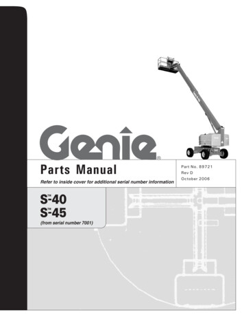
ENGINEENGINE COMPONENTS INSPECTION AND SERVICINGENGINE COMPONENTS AND CRANK CONNECTING RODMECHANISM INSPECTION AND SERVICINGENGINE COMPONENTS: CYLINDERCYLINDER REMOVALThe removal can be done on the vehicle body. Remove cylinder head. Remove cylinder. Remove cylinder gasket, bolts Clean cylinder gasket and remove any debris.Caution!Do not damage the cylinder area. Make sure not to drop anything,including cylinder gasket material, into the crankcase.CYLINDER INNER WALL WEAR INSPECTIONUse a bore diameter dial gauge to measure the degree of wear.The measure point is divided into three sectional planes in the axial direction: upper, middle andlower; measure every plane each time on the mutually perpendicular directions (X, Y), the measured least dimension is the cylinder bore; at the most upper position measured is the largestdiameter, and the lowest position measured is the smallest diameter, their difference is the cylindricity of the cylinder. At the same cross section, measure the difference of diameter between twopoints mutually perpendicular; which is the circularity of the cylinder.In order to make the measuring point perpendicular with the bore axis of the cylinder, and to ensure the precision of the measurement, the bar of the gauge canbe slightly swung in the direction of the gauge bar, and take the smallest readingnumber as the result.In the situation without a dial gauge, a feeler gauge can be used to make relativity measurement.put a new piston into the cylinder, and use the feeler gauge to measure the gap between thepiston skirt and the cylinder wall. T hen ¿gure out the abrasion loss of the cylinder. If the circularity of the cylinder exceeds the limit, then a cylinder reboring machine should be used to reborethe cylinder, and enlarge its diameter by 0.5mm or 1.00mm, then ¿t the piston and piston ringwhich size are also enlarged. If the wear is too severe and cannot be reworked, then a new cylinder should be installed.Cylinder boreCylindricityCircularity57.4mm0.05mm0.05mm3
&5 1. &211(&7,1* 52' 0(& 1,60 3,6721 6(73,6721 3,1 ,163(&7,21 1' 6(59,&,1* ,QVHUW WKH SLVWRQ SLQ KRUL]RQWDOO\ LQWR WKH SLVWRQ SLQ KROH DQG LQVSHFW WKH FOHDUDQFH EHWZHHQ SLV WRQ DQG SLVWRQ SLQ 6HUYLFH /LPLW PP,I WKH IUHH SOD\ LV WRR PXFK WKH ZRUQ FRQGLWLRQ RI SLVWRQ SLQ DQG SLVWRQ SLQ KROH PXVW EH LQVSHFWHG UHVSHFWLYHO\ 0HDVXUH WKH H[WHUQDO GLDPHWHU RI SLVWRQ SLQ 6HUYLFH /LPLW PP,I WKH UHVXOW LV OHVV WKDQ WKH 6HUYLFH OLPLW LW VKRXOG EH UHSODFHG IWHU UHSODFHPHQW FKHFN WKH FOHDUDQFH EHWZHHQ SLVWRQ SLQ DQG SLVWRQ SLQ KROH DQG PDNH VXUH LW FRPSOLHV ZLWK WKH UHTXLUHG PHDVXUHPHQW 0HDVXUH WKH LQQHU GLDPHWHU RI SLVWRQ SLQ 6HUYLFH /LPLW PP,I WKH UHVXOW LV PRUH WKDQ WKH VHUYLFH OLPLW LW VKRXOG EH UHSODFHG IWHU UHSODFHPHQW FKHFN WKH FOHDUDQFH EHWZHHQ WKH KROHV RI WKH SLVWRQ SLQ DQG PDNH VXUH LW FRP SOLHV ZLWK WKH UHTXLUHG PHDVXUHPHQW 3,6721 5,1*6 ,163(&7,21 1' 6(59,&,1* ,QVSHFW WKH SLVWRQ ULQJ IRU ÀDZV VHULRXV ZHDU RU VHULRXV FRQJOXWLQDWLRQ HWF ,I WKHUH LV LW VKRXOG EH UHSODFHG ,I WKH SLVWRQ ULQJ¶V ODWHUDO FOHDUDQFH DQG QRWFK FOHDUDQFH DUH WRR ODUJH RU WRR VPDOO LW ZLOO FDXVH PDOIXQFWLRQV VR LW PXVW EH PHDVXUHG 0HDVXUH WKH FOHDUDQFH RI WKH SLVWRQ ULQJ LQ WKH SLVWRQ ULQJ JURRYH 7KLV FOHDUDQFH LV WKH SLVWRQ ULQJ¶V ODWHUDO FOHDUDQFH )LUVW 5LQJ6HFRQG 5LQJ PP PP&211(&7,1* 52' (1' ,163(&7,21 3XW WKH SLVWRQ SLQ DQG EHDULQJ LQWR WKH FRQQHFWLQJ URG HQG LQVSHFW WKH GHJUHH RI WLJKWQHVV RI WKH SLVWRQ SLQ LQ FRQQHFWLQJ URG HQG 0HDVXUH WKH LQQHU GLDPHWHU RI WKH FRQQHFWLQJ URG HQG 6HUYLFH /LPLW PP:KHQ WKH DEUDVLRQ RI WKH ERUH H[FHHGV WKH OLPLWDWLRQ LW VKRXOG EH UHSODFHG 4
3,6721 5,1*6 6(7 83%HIRUH VHWWLQJ XS DSSO\ RLO RQ HDFK SLVWRQ ULQJ WKHQ HQODUJH SLVWRQ ULQJV DW WKH VDPH WLPH SXW WKHP RQ WKH SLVWRQ DQG PRYH GRZQZDUGV JUDGXDOO\ XQWLO SLVWRQ ULQJV IDOO LQWR WKH ULQJ JURRYH 3,6721 6(7 ,167 // 7,21 5HPRYH WKH JDVNHW DWWDFKHG WR WKH FUDQNFDVH 0RXQW SLVWRQ RQWR WKH VPDOO HQG RI WKH FRQQHFWLQJ URG 7KH WRS RI WKH SLVWRQ PDUNHG ZLWK ³,1 VKRXOG EH PRXQWHG WRZDUGV WKH GLUHFWLRQ RI WKH LQOHW SRUW LI WKH PDUN LV ³(; WKHQ LW VKRXOG EH PRXQWHG WRZDUGV WKH GLUHFWLRQ RI WKH H[KDXVW SRUW 0RXQW SLVWRQ SLQ DQG SLVWRQ SLQ FOLS SSO\ RLO RQ WKH SLVWRQ SLQ WR OXEULFDWH LW &RYHU WKH FUDQNFDVH SRUW ZLWK D SLHFH RI FORWK WR NHHS WKH SLVWRQ FOLS IURP GURSSLQJ LQWR WKH FUDQNFDVH &5 1. &211(&7,1* 52' 6(77KH FRQQHFWLQJ URG LV WKH FRPSRQHQW WKDW OLQNV WKH SLVWRQ DQG FUDQN 7KH SLFWXUH VKRZV WKH VWUXFWXUH DQG DVVHPEOLQJ UHODWLRQV RI WKH FUDQN FRQQHFWLQJ URG FRPSRQHQW &5 1.& 6( 1' &5 1.6 )7 5(029 /%HIRUH UHPRYLQJ WKH FUDQNFDVH DQG FUDQNVKDIW IROORZ WKHVH SURFHGXUHV 5HPRYH WKH HQJLQH 5HPRYH WKH F\OLQGHU FRYHU 5HPRYH WKH F\OLQGHU 5HPRYH WKH SLVWRQ 5HPRYH WKH GULYH SODWH DQG WKH GULYHQ SODWH 5HPRYH WKH & JHQHUDWRU 5HPRYH WKH VWDUWLQJ PRWRU 5HPRYH WKH RLO SXPS 7KHQ UHPRYH WKH FDP FKDLQ WHQVLRQHU EROW 5HPRYH WKH FDP FKDLQ WHQVLRQHU 8VH VSHFLDO WRROV WR UHPRYH WKH VWDUWLQJ GULYHQ JHDU 5
5HPRYH WKH FUDQNFDVH SRVLWLRQLQJ EROWV 6HSDUDWH WKH ULJKW FUDQNFDVH DQG WKH OHIW FUDQNFDVH %H FDUHIXO QRW WR GDPDJH WKH MRLQW IDFH 5HPRYH WKH JDVNHW DQG WKH GRZHO SLQV 5HPRYH WKH FUDQNVKDIW IURP WKH FUDQNFDVH 7DNH RXW WKH FDP FKDLQ 5HPRYH WKH JDVNHW RQ WKH FUDQNFDVH MRLQW IDFH EH FDUHIXO WR QRW GDPDJH WKH MRLQW IDFH 5HPRYH WKH RLO VHDO IURP WKH OHIW FUDQNFDVH 5HPRYH WKH RLO VHDO IURP WKH ULJKW FUDQNFDVH 6
CRANKSHAFT AND CRANKCASE INSPECTION Replace the whole set of the crankshaft if serious wear is found while inspecting. Measure theaxial trend clearance of the big end of the connecting rod. When measuring, put the large end of the connecting rod close to the crank, and insert the feelergauge between the other side and the crank, for the correct end play.Service Limit0.55mm Measure the radial trend (X,Y) clearance of the big end of the connecting rod.Service Limit0.05mm Measure the main shaft journal jump of the crankshaft.If this measurement is too great, it will cause the engine to shake abnormally, shortening thelife of the engine It must be examined carefully when inspecting.Service Limit0.10mm(A 90)0.10mm(B 105) Examine if there is any loose, or unusual sound when the crank journal bearing turns. If there is,the whole set should be changed. After cleaning the crankcase, inspect if there is any damage. Inspect whether the joint face of the crankcase is smooth and clean. While reassembling, notice if itwill affect the sealing performance between the left and right crankcase. IWHU WKH DERYH LQVSHFWLRQ LI WKH FUDQNFDVH KDV VRPH VXUIDFH GDPDJH XVH RLOVWRQH WR refinish it.If damage is too severe, replace the cover.Because the right and left crankcase axle hole must be concentric, theyshould be replaced at the same time.CRANKSHAFT AND CRANKCASE INSTALLATION Mount the crankcase oil seal. Put the cam chain into the left crankcase. Put the crankshaft into the left crankcase.Pay attention to avoid damaging the oil seal with the cam chain.7
0RXQW WKH QHZ GRZHO SLQV DQG JDVNHW RQ WKH OHIW FUDQNFDVH 7KHQ MRLQ WKH ULJKW FUDQNFDVH DQG OHIW FUDQNFDVH WRJHWKHU 7LJKWHQ WKH FUDQNFDVH SRVLWLRQLQJ EROWV 7LJKWHQLQJ 7RUTXH OEV P 0RXQW WKH VWDUWLQJ GULYHQ JHDU. 0RXQW WKH FDP FKDLQ WHQVLRQHU. 0RXQW WKH QHZ 2 ULQJ RQ WKH FDP FKDLQ WHQVLRQHU EROW SSO\ VRPH RLO RQ WKH 2 ULQJ 7LJKWHQ WKH FDP FKDLQ WHQVLRQHU EROW 7KH 2 ULQJ PXVW EH PRXQWHG LQ WKH JURRYH 9 /9( 0(& 1,60 ,163(&7,21 1' 6(59,&,1*7KH SLFWXUH VKRZV WKH FRPPRQ YDOYH WUDLQ RI D IRXU VWURNH HQJLQH 7KLV LV D NLQG RI RYHUKHDG YDOYH WUDLQ LWV LQWDNH SRUW H[KDXVW SRUW FDP VKDIW DUH DOO ORFDWHG LQ WKH F\OLQGHU KHDG WKH YDOYHV ERWWRP XS RYHU WKH FRPEXVWLRQ FKDPEHU *(1(5 / ,1752'8&7,217KH IRXU VWURNH HQJLQH FRPSOHWHV LWV IRXU VWURNH ZLWK RQH SLVWRQ VWURNH ,QWDNH VWURNH &RPSUHVVLRQ VWURNH ([SDQVLRQ VWURNH ([KDXVW VWURNH8
9 /9( &/( 5 1&( '-8670(179DOYH FOHDUDQFH LV DQ LPSRUWDQW WHFKQLFDO SDUDPHWHU LQ WKH YDOYH WUDLQ ,Q RUGHU WR enable the engine to run properly,HVSHFLDOO\ ZKHQ WKH HQJLQH LV RYHUKHDWHG RU LQ FROG FRQGLWLRQV D FHUWDLQ FOHDUDQFH PXVW EH NHSW 7KLV FOHDUDQFH LV FDOOHG YDOYH FOHDUDQFH :KHQ WKH HQJLQH LV UXQQLQJ WKH YDOYH FOHDUDQFH PXVW QRW EH WRR ELJ RU WRR VPDOO 5HPRYH WKH F\OLQGHU KHDG FRYHU ,QVSHFWLRQ DQG DGMXVWPHQW VKRXOG EH GRQH LQ FRRO FRQGLWLRQV EHORZ R& 7XUQ WKH FRROLQJ IDQ FORFNZLVH XQWLO WKH PDUN RI WKH WLPLQJ GULYH VSURFNHW RQ WKH FDPVKDIW LV DW WKH WRS GHDG FHQWHU DQG WKH ³7 V\PERO RU RWKHU PDUN RI WKH PDJQHWR À\ZKHHO DOLJQV WR WKH FUDQN FDVH PDUN 7KH FUDQNVKDIW VKRXOG URWDWH RU WKH H[KDXVW SRUW PD\ QRW EH DGMXVWHG :KHQ DGMXVWLQJ ORRVHQ WKH ORFN QXWV DGMXVW WKH EROWV ZLWK D YDOYH DGMXVWLQJ ZUHQFK. WKHQ WXUQHG FORFNZLVH WKH YDOYH FOHDUDQFH GHFUHDVHV WKHQ WXUQHG FRXQWHUFORFNZLVH WKH YDOYH FOHDUDQFH LQFUHDVHV 3XW D IHHOHU JDXJH ZLWK VSH FL¿F VL]HV EHWZHHQ WKH YDOYH DQG URFNHW WR FKHFN IRU FRUUHFW FOHDUDQFH 7DNH RXW WKH IHHOHU JDXJH WLJKWHQ WKH ORFN QXWV DQG WKHQ LQVSHFW WKH YDOYH FOHDUDQFH DJDLQ 6RPHWLPHV ZKHQ WLJKWHQLQJ WKH ORFN QXWV WKH FOHDUDQFH ZLOO FKDQJH VR LW PXVW EH UHFKHFNHG IRU WKH SURSHU FOHDUDQFH 9DOYH &OHDUDQFH a PP9
& 06 )7 7KH FDPVKDIW LV the PDLQ GULYLQJ XQLW RI WKH YDOYH WUDLQ 7KH DLU LQOHW FDP WKH H[KDXVW FDP DQG WKH FDP MRXUQDO DUH RQ WKH VKDIW ,W causes WKH LQWDNH DQG H[KDXVW YDOYH WR RSHQ DQG FORVH DW WKH FRUUHFW WLPH :HDU WR WKH FDPVKDIW ZLOO DIIHFW HQJLQH SHUIRUPDQFH DQG FDXVH H[FHVVLYH QRLVH & 06 )7 5(029 / /RRVHQ YDOYH FRYHU EROWV DQG UHPRYH FRYHU 5HPRYH WKH FDP FKDLQ WHQVLRQDO EROW FDS DQG UHPRYH WKH 2 ULQJ 7LJKWHQ WKH FDP FKDLQ WHQVLRQHU E\ DGMXVWLQJ EROW FORFNZLVH 7XUQ WKH À\ZKHHO FRXQWHUFORFNZLVH WR PDNH WKH ³ 7 PDUN RQ WKH À\ZKHHO DOLJQ ZLWK WKH PDUN RQ WKH FUDQNFDVH :KHQ WKH KROH RQ WKH FDP FKDLQ WLPLQJ GULYH FKDLQ ZKHHO LV XS LW VKRXOG EH DW WKH WRS GHDG FHQWHU 5HPRYH WKH F\OLQGHU KHDG SRVLWLRQLQJ EROW 5HPRYH WKH FDPVKDIW KROGHU EROW FDS DQG ZDVKHU 5HPRYH WKH FDPVKDIW KROGHU DQG GRZHO SLQ 5HPRYH WKH FDP FKDLQ ZKHHO IURP WKH FDP FKDLQ DQG UHPRYH WKH FDPVKDIW & 06 )7 ,163(&7,21 ,QVSHFW WKH FDPVKDIW EHDULQJV IRU SOD\. II WKHUH LV too much play, UHSODFH WKH ZKROH VHW ,QVSHFW FDP VXUIDFH IRU GDPDJH 0HDVXUH WKH KHLJKW RI WKH FDP ,QOHW &DP([KDXVW &DP PP PP 0
CAMSHAFT INSTALLATION 5RWDWH WKH À\ZKHHO WR DOLJQ WKH ³7 PDUN RQ WKH À\ZKHHO ZLWK WKH FDPVKDIW PDUN 7KH URXQG KROH RQ WKH FDP FKDLQ ZKHHO VKRXOG EH XS DQG WKH OHIW DQG ULJKW VLW SDUDOOHO ZLWK WKH F\OLQGHU KHDG WKH OREHV RI WKH FDPVKDIW DUH GRZQ 7KHQ LQVWDOO WKH FDPVKDIW RQ WKH F\OLQGHU KHDG 0RXQW WKH FDP FKDLQ RQ WKH FKDLQ ZKHHO ,QVWDOO WKH GRZHO SLQV 0RXQW WKH FDPVKDIW KROGHU ZDVKHU DQG EROW FDS RQ WKH F\OLQGHU KHDG 7LJKWHQ WKH F\OLQGHU KHDG EROW DQG QXW :KLOH LQVWDOOLQJ DSSO\ VRPH RLO RQ WKH WKUHDG RI WKH FDPVKDIW KROGHU EROW 7KH FDPVKDIW QXWV VKRXOG EH WLJKWHQHG GLDJRQDOO\ LQ D VWHS SURFHVV IWHU LQVWDOOLQJ DGMXVW WKH YDOYH FOHDUDQFH 7XUQ WKH FDP FKDLQ WHQVLRQHU DGMXVWLQJ EROW FRXQWHU FORFNZLVH DQG UHOHDVH WKH ORFN SSO\ RLO RQ WKH QHZ 2 ULQJ 0RXQW DQG WLJKWHQ WKH FDP FKDLQ WHQVLRQHU FRYHU EROW 7KH 2 ULQJ PXVW EH PRXQWHG SURSHUO\ LQ WKH JURRYH 5HSODFH WKH YDOYH FRYHU JDVNHW DQG PRXQW WKH FRYHU 7KH YDOYH FRYHU JDVNHW PXVW EH SURSHUO\ PRXQWHG LQ WKH JURRYH 7LJKWHQ WKH YDOYH FRYHU SRVLWLRQLQJ EROW ROCKER ARM AND ROCKSHAFTROCKER ARM AND ROCKSHAFT REMOVAL 5HPRYH WKH FDPVKDIW KROGHU 7DNH RXW WKH URFNVKDIW E\ UHPRYLQJ WKH EROW 5HPRYH WKH URFNHU DUP ROCKER ARM AND ROCKSHAFT INSPECTION,QVSHFW LI WKHUH LV DQ\ DEUDVLRQ RU GDPDJH RQ WKH URFNHU DUP DQG URFNVKDIW RU LI WKH RLO KROH LV FORJJHG ,I WKHUH LV DEUDVLRQ RQ WKH VXUIDFH RI WKH URFNHU DUP WKH FDPVKDIW VKRXOG DOVR EH LQVSHFWHG 11
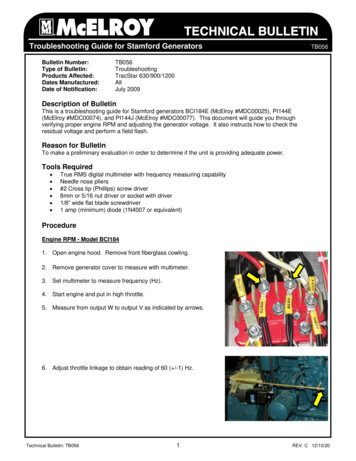
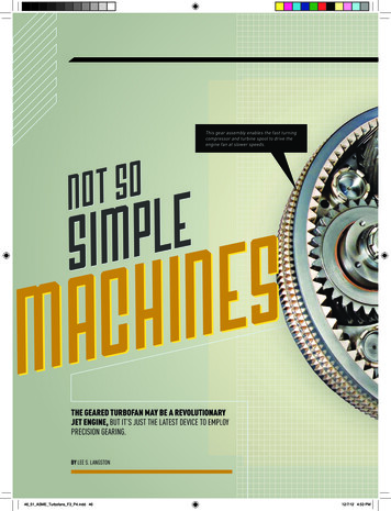
Measure the inner diameter of the rocker arm.Service Limit10.04mm Measure the outer diameter of the rockshaft.Service Limit9.96mmROCKER ARM AND ROCKSHAFT INSTALLATION 噝 R ead the “ EX” mark on the camshaft holder, then mount the exhaust port rocker arm to the rockshaft. M ount the inlet port rocker arm to the rockshaft. Apply some oil to the rockshaft before mounting.CAM CHAIN TENSIONERThe chain tensioner must be in good working condition for proper chain tension.1. Cam chain2. Cam chain tensioner3. Cam chain tensioner lifter.4. Gasket5. Cam chain tensioner pivot6. Cam chain guide7. Bolt8. Nut9. O-ring10. O-ringThe operational principle of the tensioner is as shown in the picture.As for the adjustment of the cam chain tensioner, clockwisetightens, and counterclockwise loosens.12
VALVE AND VALVE SPRINGVALVE AND VALVE SPRING REMOVAL Remove cylinder head. Remove valve cotter pin and compressor. Remove upper spring race. Remove valve spring. Remove lower spring race. Remove valve stem oil seal. Remove valve.The removed parts should be placed in order toavoid confusion. It’s better to place the intake valveparts and exhaust valve parts separately.VALVE AND VALVE SPRING INSPECTION Inspect the valve for bending or burning. Inspect for smooth action between the valve and the valve guide. Measure the outer diameter of the valve stem.Service Limit4.94mm Measure the free length of the inner and outer valve spring.ValveInner springOuter springInlet valve31.2mm34.1mmExhaust valve31.2mm34.1mmVALVE AND VALVE SPRING INSTALLATION Mount the spring retainer, valve guide oil seal.It is recommended to replace the valve guide oil seal with a new one. After applying oil on the valve stem, mount it into the valve guide. Mount the inner and outer valve springs. Mount the valve locker with a spring compressor.When mounting, the twisting direction of the inner and outer springs must be opposite. Tap on the valve gently two or three times with a rubber hammer to make the valve and the valvelock connect well.Do not damage the valve.13
VALVE GUIDECarbon accumulation on the valve guide will make thevalve move roughly, causing the valve to notopen or close properly.Valve guide abrasion is one of the causes of white smoke from the exhaust pipe.TO CLEAN CARBON ACCUMULATION OFF THE VALVE GUIDE Remove the valve and springs etc. Clean the carbon accumulation with a valve guide reamer.Generally, only turn right when using the reamer, and do notpush in or out directly with the reamer.VALVE GUIDE INNER DIAMETER MEASUREMENTService Limit5.03mmCalculate the clearance between the valve stem and the valve guide(the inner diameter of the guide subtracted by the outer diameter of the valve stem).ValveService LimitInlet valve0.08mmExhaust valve0.10mmWhen the abrasion of the valve guide exceeds the service limit, it should be replaced; after replacing a new valve guide, the valve retainer must be adjusted.VALVE GUIDE REPLACEMENT Heat the cylinder head to 212 302 F (100 150 C)The cylinder head must be wholly and quickly heatedWR WKH VSHFL¿F GHJUHH DQG FDQQRW EH KHDWHG SDUWOy, orit will cause the cylinder head to distort. The temperature is very high, two technicians are recommended. Tap the valve guide out with a valve guide remover or similar tool.Do not damage the cylinder joint face14
After tapping the valve guide, you need to trim it with a reamer.When using the reamer, cutting oil must be used. The reamercan only be turned right; do not push in or out directly. Clean the cylinder head, and remove the scraps generated while ramming.VALVE SEATThe relative position between the valve seat and the working surface of the valve is very important forthe valve to seal properly.VALVE SEAT WIDTH MEASUREMENT Clean the carbon accumulation in the combustion chamber. Measure the width of the valve seat with a vernier caliper.StandardService Limit0.6-1.2mm1.8mmWhen abrasion causes the valve seat width to be uneven, too wide ortoo narrow, it will result in poor contact between the valve and the valveseat, and not seal tight. At this time it must be reamed with a customized valve seat milling cutter.The valve seat milling cutter is the customized trimming tool for thevalve seat, and it has three cutting angles: 32, 45, and 60.While trimming, press the valve seat milling cutter to make rotary motion with 40 50 N force.Some oil must be applied on the valve seat milling cutter, to eliminate scraping when trimming.VALVE SEAT FINISHING Ream out the defects on the working surface with a 45 coarsetooth milling cutter.Do not ream too much.15
5HDP WKH XSSHU DQJOHV RI WKH YDOYH VHDW ZRUNLQJ VXUIDFH ZLWK D PLOOLQJ FXWWHU 5HDP WKH ORZHU DQJOHV RI WKH YDOYH VHDW ZRUNLQJ VXUIDFH ZLWK D PLOOLQJ FXWWHU )LQDOO\ UHDP WKH YDOYH VHDW WR WKH VSHFL¿F VHDW ZLGWK ZLWK D PLOOLQJ FXWWHU 9 /9( 6( 7 728& ,1* 326,7,21 ,163(&7,21 SSO\ D WKLQ OD\HU RI ÀXLG RQ WKH YDOYH VHDW. Place WKH YDOYH RQ WKH VHDW DQG URWDWH MRLQWO\; WKHQ WDNH RXW WKH YDOYH DQG REVHUYH WKH FRQWDFW VXUIDFH RQ WKH YDOYH IDFH ,I WKH FRQWDFW SRVLWLRQ LV WRR KLJK FXW RXW VRPH RI WKH XSSHU SDUW RI WKH YDOYH VHDW ZLWK D PLOOLQJ FXWWHU WR UHGXFH WKH ZRUNLQJ IDFH RI WKH YDOYH VHDW ,I WKH FRQWDFW SRVLWLRQ LV WRR ORZ WKHQ FXW RXW VRPH RI WKH ORZHU SDUW RI WKH YDOYH VHDW ZLWK D PLOOLQJ FXWWHU WR UDLVH WKH ZRUNLQJ IDFH RI WKH YDOYH VHDW )LQDOO\ PLOO WKH ZRUNLQJ IDFH RI WKH YDOYH VHDW WR WKH VSHFL¿F ZLGWK ZLWK D PLOOLQJ FXWWHU ,I WKH YDOYH VHDW VWLOO FDQQRW FRQWDFW HYHQO\ ZLWK WKH YDOYH DIWHU WULPPLQJ WKH YDOYH VKRXOG EH UHYLVHG RU UHSODFHG 16
9 /9( 1' 9 /9( 6( 7 / 33,1* IWHU ¿QLVKLQJ WKH YDOYH DQG VHDW VKRXOG EH ODSSHG LQ RUGHU WR PDNH WKHP VHDO SURSHUO\ 6SUHDG D WKLQ OD\HU RI VLOLFRQ FDUELGH RQ WKH ZRUNLQJ EHYHO RI WKH YDOve. UVing D YDOYH VXFWLRQ FXS WRRO, UHSHDWHGO\ URWDWH WKH YDOYH VXFWLRQ FXS WR ODS WKH YDOYH DQG YDOYH VHDW HYHQO\ XQWLO WKH\ PDWFK WLJKWO\ %HIRUH ODSSLQJ FOHDQ WKH YDOYH YDOYH VHDW DQG YDOYH JXLGH :KHQ ODSSLQJ GR QRW XVH WRR PXFK IRUFH 'XULQJ ODSSLQJ GR QRW GURS DQ\ VLOLFRQ FDUELGH LQWR WKH area EHWZHHQ WKH YDOYH OHYHU DQG WKH YDOYH JXLGH 9 /9( 1' 9 /9( 6( 7 ,5 ,03(50( %,/,7 ,163(&7,21 IWHU ODSSLQJ WKH YDOYH DQG YDOYH VHDW WKH DLU LPSHUPHDELOLW\ RI WKH MRLQW VXUIDFH VKRXOG EH LQ VSHFWHG 0HWKRG 2QH Follow the same method as for ³YDOYH VHDW FRQWDFW SRVLWLRQ LQVSHFWLRQ 0HWKRG 7ZR HYHQO\ GUDZ VHYHUDO OLQHV RQ WKH ZRUNLQJ VXUIDFH RI WKH YDOYH ZLWK D SHQFLO 3lace WKH YDOYH LQWR WKH YDOYH VHDW. Turn a ULQJ. If the lines are all broken, the level of airLPSHUPHDELOLW\ LV satisfactory 0HWKRG 7KUHH MRXQW WKH YDOYH RQ WKH F\OLQGHU KHDG DQG ¿OO WKH LQOHW DQG H[KDXVW YHQW ZLWK QRQ ÀDPPDEOH VROYHQW DQG SUHVHUYH IRU PLQXWHV LI WKHUH LV QR OHDNDJH WKH YDOYH LV VHDWHG FRUUHFWO\ 17
LUBRICATION SYSTEM INSPECTION AND SERVICINGGENERAL INTRODUCTIONThe picture shows the functional diagram of the lubrication system. After the lubrication oil crossesWKH ¿OWHU VFUHHQ, it is pumped by the rotator oil pump. Some of the oil goes into the big end of theconnecting rod and splashes on the cylinder wall and the small end of the connecting rod; the restgoes through some oil passages, such as the shaft neck of the camshaft, and splashes on thecam rockshaft and cam chain. The lubrication oil that falls back into the oil groove can be recirculated.18
2,/ 6 67(0 ,163(&7,21 1' 5(3/ &(0(172,/ 5(3/ &(0(17 7LJKWHQ WKH GLSVWLFN. 5HPRYH WKH RLO ¿OWHU VFUHHQ FDS DQG WKH VFUHHQ WR allow WKH RLO ÀRZ RXW ,QVSHFW WKH VFUHHQ DQG 2 ULQJ. Replace if damaged. 0RXQW and tighten WKH RLO ¿OWHU VFUHHQ DQG WKH VFUHHQ FRYHUV. 6XSSO\ WKH DSSOLFDWLRQ VSHFL¿F RLO WR WKH appropriate OHYHO 2LO /HYHO'LVDVVHPEOLQJ O5HSODFLQJ O6WDUW WKH HQJLQH DQG UXQ IRU VHYHUDO PLQXWHV LQ WKH LGOH SRVLWLRQ WR PDNH VXUH WKHUH LV QR RLOOHDkage. Stop the engine and inspect for proper oil level.527 5 2,/ 38037KH RLO SXPS LV WKH FULWLFDO FRPSRQHQW RI WKH OXEULFDWLRQ V\VWHP. Inspect and maintain it SHULRGLFDOO\. If GDPDJHG VHULRXVO\, replace it as a unit.2,/ 3803 5(029 / 5HPRYH WKH À\ZKHHO RI WKH PDJQHWR 5HPRYH WKH VWDWRU FRLO DQG WULJJHU ZLQGLQJ 5HPRYH WKH ULJKW FUDQNFDVH FRYHU EROWV, followed by removing WKH ULJKW FUDQNFDVH FRYHU 5HPRYH WKH JDVNHW DQG GRZHO SLQV 19
5HPRYH WKH VWDUWLQJ UHGXFWLRQ JHDU DQG VWDUWLQJ FOXWFK 5HPRYH WKH RLO SXPS SDUWLWLRQ SODWH SRVLWLRQLQJ EROWV followed by removing WKH RLO SXPS SDUWLWLRQ SODWH 5HPRYH WKH RLO SXPS GULYLQJ JHDU QXWV followed by UHPRYing WKeGULYLQJ JHDU DQG FKDLQ After removing WKH RLO SXPS SRVLWLRQLQJ EROWV UHPRYH WKH RLO SXPS DVVHPEO\ 5HPRYH WKH VFUHZV DQG GLVDVVHPEOH WKH RLO SXPS 2,/ 3803 ,163(&7,21 ,QVSHFW WKH FOHDUDQFH EHWZHHQ WKH RLO SXPS ERG\ DQG WKH RXWHU URWDWRU 6HUYLFH /LPLW PP ,QVSHFW WKH FOHDUDQFH EHWZHHQ WKH LQQHU URWDWRU DQG WKH RXWHU URWDWRU 6HUYLFH /LPLW PP ,QVSHFW WKH FOHDUDQFH EHWZHHQ WKH URWDWRU SODQH DQG WKH RLO SXPS 6HUYLFH /LPLW PP,I WKH LQVSHFWLRQ UHVXOW H[FHHGV WKH DERYH VWDWHG VHU YLFH OLPLW WKH ZKROH VHW VKRXOG EH UHSODFHG 0
2,/ 3803 66(0%/,1* VVHPEOH WKH LQQHU DQG RXWHU URWDWRUV RI WKH SXPS DQG PRXQW WKH RLO SXPS VKDIW :KHQ DVVHPEOLQJ DOLJQ WKH XQ¿OOHG FRUQHU RI WKH RLO SXPS VKDIW ZLWK WKH FRUQHU RI WKH LQQHU URWDWRU DQG WKHQ PRXQW 0RXQW WKH GRZHO SLQ \RX FDQ LQVWDOO LW DIWHU DOLJQLQJ WKH RLO SXPS SODWH ZLWK WKH GRZHO SLQ 7LJKWHQ WKH RLO SXPS SODWH EROWV IWHU DVVHPEOLQJ JHQWO\ WXUQ WKH RLO SXPS VKDIW DQG PDNH VXUH WKH RLO SXPS FDQ WXUQ VPRRWKO\ 2,/ 3803 ,167 // 7,21 ,QVWDOO WKH RLO SXPS RQ WKH FUDQNFDVH %HIRUH LQVWDOOLQJ ¿OO WKH RLO SXPS ZLWK RLO :KHQ LQVWDOOLQJ WKH DUURZ RI WKH RLO SXPS ERG\ PXVW EH SRLQWLQJ XSZDUGV 7LJKWHQ WKH RLO SXPS SRVLWLRQLQJ EROWV OLJQ WKH RLO SXPS GULYLQJ JHDU ZLWK WKH RLO SXPS VKDIWV XQ¿OOHG FRUQHU WKHQ PRXQW WKH GULYLQJ JHDU DQG FKDLQ 0RXQW WKH GULYLQJ JHDU SRVLWLRQLQJ QXW DQG WLJKWHQ LW ,QVWDOO WKH SDUWLWLRQ ERDUG DQG WLJKWHQ EROWV ,QVWDOO WKH VWDUWLQJ UHGXFWLRQ JHDU DQG VWDUWLQJ FOXWFK 0RXQW WKH JDVNHW DQG GRZHO SLQV 1
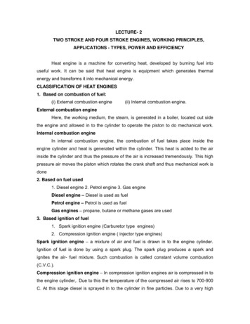
Mount the right crankcase cover positioning bolt. Mount the trigger winding and the stator coil. Tighten the right crankcase cover positioning bolt.The bolt should be gradually diagonally tightened intwo to three steps. IWHU ¿QLVKLQJ WKH LQVWDOODWLRQ LQspect for any oil leaks.FUEL SUPPLY SYSTEM INSPECTION AND SERVICINGCV CARBURETORThe CV carburetor is a constant vacuum carburetor. The picture shows the structure of the CVcarburetor.1. Gasket set2. Float valve set3. Needle jet set4. Float set5. Float chamber set6. Screw set A7. Screw set B8. Valve plate set9. Starter valve set10. Air cut valve set11. Compression coil spring12. Screw13. Carburetor assy.14. Top comp.15. Vacuum piston comp.16. Needle jet holder17. Plate clip18. Holder cap19. Tube A20. Tube B21. Screw22. Screw23. Washer screw24. Washer screw25. Washer screw26. Clip27. Clip28. Tube29. Main jet30. Slow jet41622
CARBURETOR IDLING ADJUSTMENTAIR ADJUSTING SCREW ADJUSTMENTStep one: T urn on the air adjusting screw in the turn out by the prescribed number of turns.Turn out number of turns2 3/4 – 2 1/4Step two: Adjust the throttle by adjusting the screw to the prescribed idle rpm.Step three: Left and right, adjust the air adjusting screw slightly to ¿nd the highest positionof the rpm.Increase throttle quickly and gently (the rpm is from low to high), and return throttle immediately,then observe 10 to 15 minutes, to observe if the idle remains the same.VACUUM CHAMBERThe picture shows the structure of the vacuum chamber of theCV carburetor.VACUUM CHAMBER REMOVAL Remove the body cover. Remove the automatic chokelead wire. Loosen the fuel drain bolt, and drain the fuel in the Àoatchamber. Remove the fuel line and the vacuum pipe. Loosen the throttle cable adjusting nut and positioning nut;remove the throttle cable. Loosen the carburetor air inlet vent clip and the inlet manifold clip;remove the carburetor. Remove the vacuum cover bolt, and remove the vacuum cover.Notice: move slowly to prevent the spring from ejecting. Take out the spring, the vacuum membrane and the plunger. Press down the holding clamp of the needle valve top, and turn leftto take out the clamp. Take out the spring and needle valve.Do not damage the vacuum membrane. Inspect the needle valve for wear. Inspect the vacuum membrane for damage. Inspect the plunger for damage.23
9 &880 & 0%(5 ,167 // 7,21 0RXQW WKH SOXQJHU DQG WKH YDFXXP PHPEUDQH LQWR WKH FDUEXUHWRU ERG\ 3XVK WKH SOXQJHU XSZDUGV LQ WKH GLUHFWLRQ RI WKH YDFXXP FKDPEHU FRYHU WR RSHQ WKH FDUEXUHWRU MHW WXEH Insert the spring OLJQ WKH EXOJH SDUW RI WKH YDFXXP PHPEUDQH ZLWK WKH ¿OOLVWHU RI WKH FDUEXUHWRU ERG\; PRXQW WKH vacuumFKDPEHU FRYHU 7LJKWHQ WKH EROW 8720 7,& 6,'( 67 57(5 & 2.( 8720 7,& 6,'( 67 57(5 ,163(&7,21 5HPRYH WKH IXHO KRVH IURP WKH FDUEXUHWRU 7XUQ RXW WKH FDUEXUHWRU ÀRDW FKDPEHU GUDLQ VFUHZ DQG GUDLQ WKH IXHO LQ WKH FDUEXUHWRU 5HPRYH WKH DXWRPDWLF VLGH VWDUWHU OHDG ZLUH DQG UHPRYH WKH FOLS 5HPRYH WKH FDUEXUHWRU FODPS DQG UHPRYH WKH FDUEXUHWRU &KHFN WKH FRQGLWLRQ RI WKH FRQQHFWLRQ EHWZHHQ WKH WZR OHDG ZLUHV 7KH FKRNH YDOXH VKRXOG EH EHORZ 9 ,I LW H[FHHGV WKH VSHFL¿F YDOuH LW VKRXOG EH UHSODFHG :KHQ WKH HQJLQH LV FROG OLQN D KRVH RQ WKH UHVHUYH VXSSO\ IXHO OLQH DQG EORZ YHU\ JHQWO\ ,I LW LV RE VWUXFWHG RU WKH DXWR VLGH VWDUWHU LV QRW JRRG LW VKRXOG EH UHSODFHG 5HPRYH WKH DXWR VLGH VWDUWHU FRYHU 5HPRYH LWV SRVLWLRQLQJ EROWV DQG SLHFHV 5HPRYH WKH DXWR VLGH VWDUWHU ,QVSHFW WKH DXWR VLGH VWDUWLQJ YDOYH DQG IXHO LQMHFWLRQ QHHGOH IRU ZHDU ,QVSHFW WKH 2 ULQJ for ZHDU )/2 7 & 0%(5)/2 7 & 0%(5 5(029 / 5HPRYH WKH FDUEXUHWRU 5HPRYH WKH FODPS DQG UHPRYH WKH ÀRDW FKDPEHU 5HPRYH WKH 2 ULQJ; WXUQ RXW WKH ÀRDW FKDPEHU VFUHZ; UHPRYH WKH ÀRDW SLQ; DQG UHPRYH WKH ÀRDW DQG ÀRDW YDOYH 5HPRYH WKH FKRNH DGMXVWLQJ VFUHZ DQG DLU DGMXVWLQJ VFUHZ 24
Before removing ¿rst tighten the two screws gently, counting the number of turns Remove screws. Do not use excessive force to avoid damaging the air adjusting screwhead surface. Remove the main fuel injection nozzle and fuel injection needle seat.FLOAT CHAMBER INSTALLATION,QVSHFW WKH ÀRDW IRU DQ\ GDPDJH DQG IRU IXHO LQ WKH ÀRDW ,QVSHFW WKH ÀRDW YDOYH DQG Àoat valveseat for wear. If there is wear, it should be replaced.Clear every fuel line and air line on the carburetor body with compressed air.FLOAT CHAMBER INSTALLATION Install the main fuel injection nozzle and fuel injection needle seat. Install the air adjusting screw and choke adjusting screw, and turn them to the proper position according to the noted number of turns while removing. 0RXQW WKH ÀRDW YDOYH WKH ÀRDW DQG WKH ÀRDW SLQ TLJKWHQ WKH ÀRDW SLQ SRVLWLRQLQJ VFUHw.FUEL LEVEL INSPECTION Measure the fuel level height.Fuel level height18.5mm ,QVSHFW WKH ÀRDW IRU DQ\ GDPDJH DQG LQVSHFW WKH Àoat valve for excess we
service manual 150cc engine. chassis nuts and bolts 1 engine 3 lubrication system 18 fuel supply system 22 transmission components 27 electrical starting system 30 belt drive cvt mechanism 36 clutch 40 rear transmission system 45