Transcription
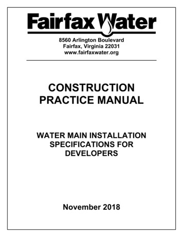
8560 Arlington BoulevardFairfax, Virginia 22031www.fairfaxwater.orgCONSTRUCTIONPRACTICE MANUALWATER MAIN INSTALLATIONSPECIFICATIONS FORDEVELOPERSNovember 2018
THIS PAGE LEFT INTENTIONALLY BLANK
SECTION 00010TABLE OF CONTENTSSectionTitle000100007000200Table of ContentsIntroduction and DefinitionsInstruction to Contractors and DevelopersSPECIFICATIONSDIVISION 1 – GENERAL REQUIREMENTSSectionTitle0133001720SubmittalsField Engineering and SurveyingDIVISION 2 – SITE 2514Excavating, Backfilling, and CompactingTrenchless Crossings and Open Cut CasingsWater Mains and AppurtenancesThrust RestraintsDisinfection of Water Distribution SystemsLeakage TestsDIVISION 3 - CONCRETESectionTitle032000330003400Concrete ReinforcementCast-in-Place ConcretePrecast ConcreteDIVISION 5 – METALSSectionTitle05500Metal FabricationsDIVISION 9 – FINISHESSectionTitle09900Special CoatingsDIVISION 13- SPECIAL CONSTRUCTIONSectionTitle13110Cathodic ProtectionConstruction Practice Manual00010-111/21/2018
APPENDICESA – Standard DetailsB – Approved Wet Tap Contractor ListC – Approved Products ListEND OF SECTION 00010Construction Practice Manual00010-211/21/2018
SECTION 00070INTRODUCTION AND DEFINITIONSINTRODUCTIONThe Fairfax Water Construction Practice Manual establishes the technical requirements for constructionof water mains to be owned, operated and maintained by Fairfax Water; and provides contractors anddevelopers with a set of guidelines to ensure conformance with Fairfax Water’s construction principles.Although the goal of this manual is to be comprehensive, it is understood that a unique situation mayarise requiring a modification of Fairfax Water’s standard construction. Final acceptance of any system,including variances from and exceptions to these guidelines when deemed appropriate, is ultimately atthe direction and discretion of Fairfax Water. This manual is a supplemental reference, to be used inconjunction with Fairfax Water’s Approved Products List, Standard Details, the Fairfax County PublicFacilities Manual (PFM) and all other Fairfax Water publications governing construction, and is notintended to supersede any of these documents.DEFINITIONSDefinitions: The following words and terms, or pronouns used in their stead, shall, wherever they appear inthis document, be construed as follows, unless a different meaning is clear from the context:“Approved Drawings” shall mean only those drawings specifically referred to as such in the Specificationspertaining to the Developer’s project drawings approved by Fairfax County.“Approved Products List” shall mean the document, latest edition, published by Fairfax Water that lists bycategory, manufacturers’ products approved for use in the Fairfax Water system available at:www.fairfaxwater.org/developers-engineers, latest edition.“Fairfax Water” shall mean the organization and its representatives chartered by the Virginia StateCorporation Commission as a public, non-profit water utility."Authorized Representative" shall mean a representative of Fairfax Water acting within the scope of hisduties."Contractor" shall mean the corporation, limited liability company, partnership or other entity which contractswith the Developer to perform the Work."Developer" shall mean the entity that has obtained an Approved Plan from Fairfax County."Engineer" shall mean the Engineer or Engineers employed by the Developer to act as such and designatedto observe the performance of the Work of the Contractor.“Project” shall mean the entire improvement, which is subject to the Specifications.“Standard Details” shall mean those details provided by Fairfax Water within this document and found at:www.fairfaxwater.org/developers-engineers, latest edition."Shop Drawings" shall mean all drawings, diagrams, illustrations, schedules, and other data orinformation that are specifically prepared or assembled by or for the Contractor and submitted by theContractor or Developer to illustrate some portion of the Work. Shop Drawings are not ApprovedDrawings as so defined."Specifications" shall mean all of the directions, requirements and standards of performance applying to theWork, hereinafter detailed and designated as such.“Work” shall mean everything explicitly or implicitly required to be furnished and done by the Contractor orDeveloper pursuant to the Specifications and Approved Drawings.Construction Practice Manual00070-111/21/2018
END SECTION 00070Construction Practice Manual00070-211/21/2018
SECTION 00200INSTRUCTION TO CONTRACTORS AND DEVELOPERSPART 11.01GENERALDESCRIPTIONA. This Section specifies the general policies and procedures for Fairfax Water Construction andFinal Acceptance requirements.1.02REQUIREMENTS FOR CONSTRUCTIONA. Fairfax Water maintains a list of Approved Products, which may be found online at:www.fairfaxwater.org/developers-engineers. Please refer to this list before ordering materials; thislist supersedes any product information mentioned in the manual.B. Fairfax Water Standard Details may be found at: www.fairfaxwater.org/developers-engineers.C. Fairfax Water does not issue or obtain permits for construction. The contractor shall obtain allnecessary permits prior to beginning work.D. The Developer/Engineer/Contractor is responsible for providing two copies of County approvedand stamped Site Plans, Minor Site Plans, or Rough Grading Plans to Fairfax Water prior toconstruction. One copy of the Land Use Permit, showing water installation/removal is approved,shall be provided with Rough Grading Plans.E. Rough Grading Plan approval by Fairfax Water allows the contractor to install the water mains;however, prior to construction the developer must submit a letter to Fairfax Water’s ConstructionDepartment stating the mains will not be filled, flushed, tested, tapped, sampled, or connected toany active Fairfax Water line until Fairfax County site plan approval is obtained and approvedplans are transmitted to Fairfax Water. Please call the Fairfax Water Construction Department at(703) 289-6388 for letter requirements.F. Prior to beginning work, construction plans must be approved and all easements recorded.Please call the Fairfax Water Construction Department at (703) 289-6388 to confirm that this hasbeen completed before scheduling work.G. All scheduled outages require a minimum of 72 hours notice so that Fairfax Water may providesufficient notice to its customers. All scheduled outages which affect customers must take placeTuesday through Thursday; no outages will be scheduled for Mondays, Fridays, Weekends, orany Holidays. All shutdowns will only be scheduled which do not affect Fairfax Water’s normaloperation. The Contractor may be required to work overtime, nights and weekends in makingthese connections if connections need to be made at times other than those specified. TheContractor may be required to use more than one crew to work simultaneously on multipleconnections.H. All water outages shall be at the discretion of the Fairfax Water Inspector.I.Provide the Fairfax Water Construction Department a minimum 72-hour notice prior to startingwork at (703) 289-6388.J.Schedule a meeting with the Fairfax Water Inspector or Inspection Supervisor prior to startingwork in order to review materials, sequencing plan and constructability issues.K. Once construction starts, all issues that cannot be resolved by the Fairfax Water Inspector orInspection Supervisor will be handled by the Chief Construction Engineer who can be reached at(703) 289-6351.Construction Practice Manual00200-13/21/2019
L. Fairfax Water maintains a List of Approved Wet Tap Contractors. Only contractors and theirforemen who are on this list are authorized to make taps in our system. Please consult this listbefore scheduling a wet tap to assure that the contractor you intend to use is on this list. See listof approved wet tap contractors, which may be found online ractorsM. A Fairfax Water Inspector must be present to inspect all aspects of the water main construction toassure conformance with approved plans and Fairfax Water specifications (i.e. materials,bedding, backfill, polyethylene encasement, thrust blocks, restraining systems, all connectionsetc.). If the work has been backfilled without inspection, it will be rejected and the contractor willbe required to re-excavate it for inspection prior to filling, testing, and sampling.N. All ductile iron pipe shall be push-on joint. Mechanical joint pipe will not be allowed unlessspecifically approved by the Fairfax Water Inspector.O. All ductile iron pipe shall be encased in polyethylene tubing in accordance with the DIPRAspecification and bedded and encased in VDOT 21A stone per Fairfax Water Standard Details.1.03REQUIREMENTS FOR FINAL ACCEPTANCEA. General:1.All water mains and appurtenances installed, tested, sampled, and placed in service.2.All easements recorded.3.All plans and revisions approved.4.Refer to Fairfax Water Standard Details, Fairfax Water Design Practice Manual, and theFairfax County PFM for additional details and/or requirements.B. Valve Boxes:1.All valve boxes intact, to grade, cleaned out and centered over operating nut.2.All valves operating properly.3.Valve Box covers with Fairfax Water identifier.4.Concrete pads installed around valve boxes in non-paved areas.5.Operating nut or valve stem extension within four feet of finished grade.6.Minimum two-inch overlap between top and bottom sections of valve boxes.7.No paving adjusters will be permitted.C. Fire Hydrants:1.Fire Hydrants facing correctly and functioning properly.2.Grade around fire hydrant to bury line.3.Painted in accordance with Fairfax Water specifications.4.No plantings or structures within five feet of fire hydrant.5.Hydrant proper distance from curb.Construction Practice Manual00200-23/21/2019
6.Fire hydrant not in sidewalk.D. Corrosion Control:1.Corrosion Control measures in place per approved plan and functioning properly.2.Recent test report.3.Certification Letter indicating properly functioning system.4.As-builts of test stations submitted and approved.5.Test Station boxes intact with numbers in brass marker.6.Test Stations in non-paved areas with concrete pad.E. Meter Boxes:1.Standard Fairfax Water approved Meter boxes and covers.2.Meter set fifteen inches below surface grade.3.Top of box matches surface grade.4.Cover and box intact and not damaged.F. Easement Areas:1.Easements properly graded.2.Easement restoration complete per approved plan.3.Structures and Plantings are in conformance with easement agreement language.4.No other utilities located parallel in easement.G. Asphalt Paving:1.Final lift of asphalt in place.Note: This is not an exhaustive list; there may be additional requirements that have not been namedabove.END SECTION 00200Construction Practice Manual00200-33/21/2019
NO TEXT THIS PAGEConstruction Practice Manual00200-43/21/2019
SECTION 01330SUBMITTALSPART 11.01GENERALDESCRIPTION OF REQUIREMENTSA.This Section specifies the general methods and requirements of submissions applicable to ShopDrawings and Product Data. Detailed submittal requirements are specified in subsequentsections.B.All submittals shall be clearly identified by reference to Section Number, Paragraph, DrawingNumber or Detail as applicable. Submittals shall be clear and legible and of sufficient size forpresentation of data.1.02A.SHOP DRAWINGS AND ENGINEERING DATA.General1.Submittals shall verify compliance with all current Fairfax Water published ApprovedProducts and Standard Details, and shall include drawings and descriptive information insufficient detail to show the kind, size, arrangement, and operation of component materialsand devices; the external connections, anchorages, and supports required; performancecharacteristics; and dimensions needed for installation and correlation with other materialsand equipment. When an item consists of components from several sources, Contractorshall provide a complete initial submittal including all components. Unless otherwise statedon the approved plans, or directed by a Fairfax Water Inspector, Shop Drawings andProduct Data consistent with the published Approved Products list do not need to besubmitted for Fairfax Water approval.2.Where required, Shop Drawings shall be sealed by a professional engineer licensed in theCommonwealth of Virginia.3.All submittals, regardless of origin, shall be stamped with the approval of Contractor andidentified with the name and number of the Project, Contractor's name, and references toapplicable specification paragraphs and Approved Drawings. Each submittal shall indicatethe intended use of the item in the Work. When catalog pages are submitted, applicableitems shall be clearly identified and inapplicable data crossed out. The current revision,issue number, and date shall be indicated on all drawings and other descriptive data.4.When requested, two copies of each shop drawing and necessary data shall be submittedto Fairfax Water.5.Facsimile (fax) copies will not be acceptable.6.Electronic Submittals: The Contractor has the option to transmit submittals electronically ina PDF format to Fairfax Water.7.Submittals shall contain:a. The date of submission and the dates of any previous submissions.b. The Project title and number.c.Contractor identification.Construction Practice Manual01330-111/21/2018
d. The names of:1)Contractor2)Supplier3)Manufacturere. Identification of the product, with the section number, page and paragraph(s).f.Field dimensions, clearly identified as such.g. Relation to adjacent or critical features of the work or materials.h. Applicable standards, such as ASTM or Federal Standards numbers.1.03A.i.Identification of deviations from Approved Drawings and Specifications.j.Identification of revisions on resubmittals.k.A blank space suitably sized for any necessary Contractor, Engineer, or Fairfax Waterstamps.l.Where calculations are required to be submitted by the Contractor, the calculationsshall have been checked by a qualified individual other than the preparer. Thesubmitted calculations shall clearly show the names of the preparer and of the checker.PROFESSIONAL ENGINEER (P.E.) CERTIFICATION FORM.If specifically required in other related Sections, submit a P.E. Certification for each itemrequired, in the form attached to this Section, completely filled in and stamped.Construction Practice Manual01330-211/21/2018
P.E. CERTIFICATION FORMThe undersigned hereby certifies that he/she is a professional engineer registered in the Commonwealthof Virginia and that he/she has been employed byto design(Name of Contractor)(Insert P.E. Responsibilities)in accordance with Section for theProject.The undersigned further certifies that he/she has performed the design of the, that said design is in conformance withall applicable local, state and federal codes, rules, and regulations, and that his/her signature and P.E.stamp have been affixed to all calculations and drawings used in, and resulting from, the design.The undersigned hereby agrees to make all original design drawings and calculations available to FairfaxWater (Owner) or the Owner’s representative within seven days following written request therefore by theOwner.P.E. NameContractor’s NameP.E. Registration NumberSignatureSignatureAddressTitleAddressEND OF SECTION 01330Construction Practice Manual01330-311/21/2018
NO TEXT THIS PAGEConstruction Practice Manual01330-411/21/2018
SECTION 01720FIELD ENGINEERING AND SURVEYINGPART 11.01A.1.02A.1.03A.1.04GENERALSECTION INCLUDESThe requirements related to construction to designated lines, grades and elevations.CONSTRUCTION TO LINES AND GRADESAll work shall be constructed in accordance with the lines, grades, and elevations shown onthe Approved Drawings. The full responsibility for keeping alignment and grade shall rest uponthe Contractor. Included shall be preparation of cut sheets.SURVEYSHorizontal and Vertical Controls: Base horizontal and vertical control points will be establishedor designated by the Engineer. All additional survey, layout, preparation of cut sheets, andmeasurement work shall be performed by a Land Surveyor, licensed in the Commonwealth ofVirginia, employed by the Contractor or Developer as a part of the Work. Stakeout for all watermains, with offsets of 8’-12’, shall be performed at intervals of 50 feet, at all appurtenances,and as otherwise directed by Fairfax Water. Contractor shall submit cut sheets for review andapproval by Fairfax Water prior to beginning water main installations. Cut sheets shall bestamped with the seal of a Professional Engineer or Land Surveyor, licensed in theCommonwealth of Virginia. The Contractor shall not begin work until provided a Fairfax Waterapproved copy of the cut sheet.PROTECTION OF SURVEY DATAA.Safeguarding Points: The Contractor shall safeguard all points, stakes, grade marks,monuments, and benchmarks made or established on the Work. The Contractor shall reestablish them if disturbed or destroyed and rectify all improperly installed Work.B.Safeguarding Property Corners: The Contractor shall safeguard all existing and knownproperty corners, monuments, and marks adjacent but not related to the Work and shall reestablish them if disturbed or destroyed.1.05RECORDSA.Maintain a complete, accurate log of all control and survey work as it progresses.B.Maintain an accurate record of all changes, revisions and modifications. See Design PracticeManual regarding plan revision requirements and procedures.END OF SECTION 01720Construction Practice Manual01720-111/21/2018
NO TEXT THIS PAGEConstruction Practice Manual01720-211/21/2018
SECTION 02315EXCAVATING, BACKFILLING, AND COMPACTINGPART 11.01GENERALSECTION INCLUDESA.Excavating Trenches for Water Mains and Appurtenant Facilities.B.Rock ExcavationC.Backfilling and Compacting1.02REFERENCESA.Land Use Permit Manual, Virginia Department of Transportation.B.Road and Bridge Specifications, Virginia Department of Transportation.C.ASTM D698 - Test Methods for Moisture Density Relations of Soils and Soil-AggregateMixtures Using 5.5 lb. Hammer and 12-inch Drop.D.Manual of Accident Prevention in Construction. Associated General Contractors of America.E.Occupational Safety and Health Standards-Excavation; Final Rule 29 CFR Part 1926, OSHA.F.Virginia Work Area Protection ManualG.Fairfax County Public Facilities ManualH.Virginia Administrative Code - Chapter 309 Rules for Enforcement of the Underground UtilityDamage Prevention Act1.03SUBMITTALSA.Submit Shop Drawings and material certificates of compliance in accordance with Section01330 – Submittals.B.Materials and Certifications:1. Select Fill: Submit letter of certification and list of material composition and properties fromeach supplier of select fill.2. Compaction Test Reports: Submit reports for each location of field compaction test.Reports shall include results of field density tests, moisture consent, and degree ofcompaction.1.04DEFINITIONSA.Utility: Buried pipe, conduit, or cable, surface features such as swales and ditches, andoverhead wires or cables including their supports.B.Earth: The softer materials of the outer surface of the earth. The basic constituents are theproducts of rock disintegration, glaciation, and erosion, consisting of boulders, cobbles,pebbles, sand, silt, and clay.C.Rock: The hard, firm and stable parts of the earth's crust which shall include all materials whichcannot be removed by excavation equipment of appropriate size and power for the diameterpipe being installed and requires blasting or manual or mechanical barring, wedging orhammering for removal from their original beds. Specifically included are ledges, bedrock,boulders, cement, grout, masonry or concrete larger than 1 cubic yard in volume.Construction Practice Manual02315-111/21/2018
1.05A.PART 22.01A.ADDITIONAL REGULATORY REQUIREMENTSNaturally Occurring Asbestos: The Contractor shall comply with all applicable regulations ofOSHA and the Fairfax County Health Department concerning Working requirements in areascontaining naturally occurring asbestos deposits.PRODUCTSFILL MATERIALSSelect Fill: Select fill shall meet the following requirements:1. Crushed Stone: Crushed Stone shall consist of 21A crushed stone conforming to VDOTspecifications, or an approved substitute. NOTE: No. 57 stone shall be used (in lieu of21A stone) at creek crossings and in areas containing groundwater.2. The conversion factor for Select Fill supplied by weight instead of volume will be 3000pounds per cubic yard.B.Suitable Fill: Suitable fill material shall conform to the following requirements.1. Type I: Type I material shall consist of clean earth excavated from the trench containingno stone larger than 3/4 inch across.2. Type II: Type II suitable material may be substituted for Type I suitable material, in thearea from 12 inches above top of pipe to original grade. Type II material shall contain goodearth and stone excavated from the trench.a. Stone material contained in Type II suitable fill shall not exceed 6 inches across andshall be uniformly distributed.b. Type II suitable material shall not consist of more than 50 percent stone by volume.2.02A.PART 33.01BEDDING MATERIALSBedding: Pipe bedding shall be Crushed Stone and shall meet the requirements of Paragraph2.01.A.1 above.EXECUTIONPREPARATIONA.Identify: Required lines, levels, contours, and datum.B.Protect Existing Vegetation: Protect plant life, lawns, and other features remaining as a portionof final landscaping.C.Protect Existing Features: Protect bench marks, existing structures, fences, sidewalks, paving,mailboxes, gas line markers, curbs, and other similar features from excavation equipment andvehicular traffic.D.Clearing: The site of all open cuts and excavation shall be first cleared of trees, stumps, shrubs,underground and other obstructions prior to excavation.1. Clearing within easements and rights-of-way shall be limited to the construction limitsshown on the Approved Drawings.2. Remove and dispose of cleared materials and debris unless otherwise directed by theInspector.3. Remove topsoil and stockpile for use in restoration of excavated areas.3.02A.EARTH EXCAVATIONShaping and Trimming: Excavate trenches to the widths and depths specified below, exceptwhere indicated otherwise.Construction Practice Manual02315-211/21/2018
1. Trench width at bottom of pipe:Nominal Pipe Diameter(Inches)3–46 – 1624 – 3642 – 48Trench Width (Inches)Ductile Iron24OD 18OD 24OD 302. Trench Bottom: Grade and align pipe trench bottoms to provide bearing for the full lengthof the pipe barrel. Provide bell holes for the proper assembly of pipe joints.B.Additional Excavation: In the event the Inspector determines the bedding materials in any areato be unsuitable, with or without the concurrence of the Contractor, the Contractor shallpromptly follow the direction of the Inspector in addressing such condition. Where additionalexcavation is required, the Contractor shall replace the removed material with Class Dconcrete, or select fill material as directed by the Inspector.C.Unauthorized Excavation: Wherever the excavation is carried beyond or below the lines andgrades given by the Approved Plans, except as specified above, all such excavated space shallbe refilled with such material and in such manner as may be directed in order to ensure thestability of the various structures. Beneath all structures, space excavated without authorityshall be refilled by the Contractor with Class D concrete or select fill materials, as directed bythe Inspector.D.Disposal of Material: Top soil suitable for final grading shall be stored on the site separatelyfrom other excavated material. Other surplus excavated material unsuitable for backfilling orin excess of that required for constructing fills and embankments as shown on the ApprovedDrawings shall be removed by the Contractor.E.Removal and disposal of Petroleum-Contaminated Soil and Groundwater: In areas wherepetroleum-contaminated soils are encountered along the proposed water main alignment, thecontractor, as directed by Fairfax Water, shall remove and dispose of all contaminated soilswithin the pipeline trench where the Total Petroleum Hydrocarbon (TPH) concentrationexceeds 50 mg/kg. The contractor shall remove the subject soils as directed by Fairfax Waterin accordance with applicable regulations of the Virginia Department of Environmental Quality(VDEQ), the U.S Environmental Protection Agency (EPA), Occupational Safety and HealthAdministration (OSHA), and industry-recognized removal procedures. Suitable clean fillmaterial will be put in place above newly installed water main, if non-paved area, in accordancewith Fairfax Water’s standard Trench Details. Additionally, the Contractor shall install flowablefill trench plugs at each end of the limit of contaminated soils, as required by Fairfax Water.The Contractor shall also obtain all necessary permits and inspections as required by local,state, and federal laws, rules, and regulations for the proper handling of the contaminated soilfrom its discovery to its disposal.3.03A.ROCK EXCAVATIONLimits of Rock Excavation: Excavate rock within the widths and depths specified for earthexcavation and specified in this paragraph.1. Proposed Structures: Excavate only to the bottom of structure.2. Rock Trench: Remove rock to a minimum of 6 inches below the bottom of pipe and replacewith 6 inches of select fill material for pipe bedding.3. Existing Structures: Excavate rock within 5 feet of existing structures and utilities bywedging, barring or other approved method.Construction Practice Manual02315-311/21/2018
4. Rock excavation may be performed by the use of a rock trenching machine or otherapproved method. Machine shall be adequate to excavate rock of the type and in thequantities necessary to perform the work required by this project.5. When the use of a rock trenching machine is inappropriate (such as at utility crossings),rock shall be excavated by barring, wedging or other approved methods.B.Blasting1. Blasting shall not be permitted.C.Protection of Backfill Material1. Excavated materials from rock excavation operations, that are deemed suitable for use asbackfill, shall be placed back in the trench, compacted, and protected from inclementweather prior to re-excavation for, and during new pipeline installation. If the Contractorfails to protect the suitable material, thereby allowing it to become unsuitable, he shallprovide select fill.2. Unsuitable Materials: Refer to the provisions for disposal of materials under the earthexcavation requirements of this specification section.3.04A.BACKFILLINGPipe Trenches: Backfill trenches to original grade or to such other grades as shown or directed.1. Manual Backfilling: Backfill around pipe manually with select fill, from 6 inches below thepipe up to 6 inches above the pipe in non-paved areas, unless specified otherwise herein.Limits of select fill in paved (roadway) areas, at stream crossings, under asphalt trails, orother designated areas shall be as defined on the Trench details on the ApprovedDrawings. If rock is encountered, backfill around pipe (with select fill) from below pipe, inaccordance with limits of rock excavation defined in paragraph above, up to 6 inches abovethe pipe. This material shall be placed in layers approximately 6 inches thick, up to thelimits indicated (on the trench details) on the Approved Drawings, each layer beingthoroughly tamped and compacted in place to a minimum of 95% of maximum dry densityin accordance with ASTM D698 and VDOT Road and Bridge specifications. Tamp usingtools of approved weight to the following points:Nominal Pipe Diameter16 Inches and UnderGreater than 16 InchesTop of Manual Backfilling12 Inches Above Top of Pipe6 Inches Above Top of Pipe2. Backfilling by machine in non-paved areas: After backfilling around the pipes as specifiedabove, the remainder of the trench may be backfilled by machine with suitable fill, but theWork shall be done in such a way as to prevent dropping of material directly on top of thepipe or structure. Material shall be deposited in uniform horizontal layers up to 2 feet indepth and compacted to a minimum 85% density in accordance with ASTM D698. If, dueto rain or other causes, the material is too wet for satisfactory compaction, it shall beallowed to dry partially before compacting.3. Select fill: Where select fill material is required by the Inspector to bed and backfill thepipe, this material shall be consolidated to the identical points specified where suitable fillmaterial is used as backfill. The use of select material shall be based upon the actualtrench conditions encountered and depth shall be determined by the Inspector.4. Prevention of Settlement: Where structures such as pipelines, walks, asphalt trails,driveways and roadways are to be constructed or replaced later, on backfilled areas, theentire backfill in such areas placed in layers, rolled, rammed, or otherwise thoroughlycompacted to a minimum of 95% of maximum dry density to prevent settlement.5. Use of water for compaction is prohibited.B.Backfilling Around Structures: Backfilling around thrust collars, and other structures andconduits shall be performed manually.Construction Practice Manual02315-411/21/2018
1. Removal of foreign matter: Remove lumber, rubbish, braces and refuse from behind wallsprior to starting backfill operation.2. Backfill shall be compacted to a minimum 95% density.C.Backfilling in VDOT Right-Of-Way:performed in VDOT right-of-ways:The following additional requirements apply for work1. Backfill compaction: All backfill shall be placed in layers of not greater thickness than 6inches, and shall be compacted to at least 95% of maximum dry density in accordance withVirginia Department of Transpo
Mar 21, 2019 · PRACTICE MANUAL WATER MAIN INSTALLATION SPECIFICATIONS FOR DEVELOPERS November 2018. THIS PAGE LEFT INTENTIONALLY BLANK. Construction Practice Manual 00010-1 11/21/2018 . CONCRETE Section Title 03200 Concrete Reinforcement 03300 Cast-in-Place Concrete
