Transcription
Introduction to WirelessCommunications and NetworksTongtong LiDept. Electrical and Computer EngineeringMichigan State UniversityEast Lansing, MI 48824tongli@egr.msu.eduBroadband Access Wireless Communication Lab.1Department of Electrical and Computer EngineeringMichigan State University
Outline Overview of a Communication SystemDigital vs. Analog CommunicationsExamples of Wireless Communication SystemsWhy Wireless is Different ?Wireless System ArchitectureMultiple Access TechniquesEvolution of Cellular Networks (1G 3G)Wireless Local Area Networks (WLANs), Bluetooth andPersonal Area Networks (PANs)Ad hoc networksTopics to be covered in the courseBroadband Access Wireless Communication Lab.2Department of Electrical and Computer EngineeringMichigan State University
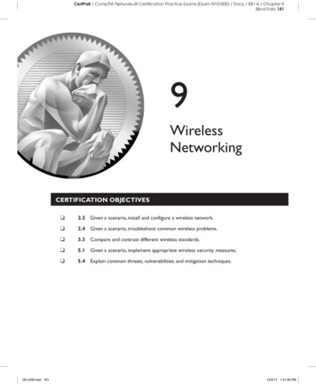
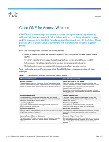
Components of a Communication System (1)Figure 1: Communication SystemsBroadband Access Wireless Communication Lab.3Department of Electrical and Computer EngineeringMichigan State University
Components of a Communication System (2) The source originates a message, which could be a human voice, atelevision picture or data. The source is converted by an input transducerinto an electrical waveform referred to as the baseband signal or messagesignal.The transmitter modifies the baseband signal for efficient transmission.The transmitter generally consists of one or more of the followingsubsystems: a pre-emphasizer, a sampler, a quantizer, a coder and amodulator.The channel is a medium through which the transmitter output is sent,which could be a wire, a coaxial cable, an optical fiber, or a radio link, etc.Based on the channel type, modern communication systems are dividedinto two categories: wireline communication systems and wirelesscommunication systems.Broadband Access Wireless Communication Lab.4Department of Electrical and Computer EngineeringMichigan State University
Components of a Communication System (3) The receiver reprocessed the signal received from the channel byundoing the signal modifications made at the transmitter and thechannel. The task of the receiver is to extract the message from thedistorted and noisy signal at the channel output. The receiver mayconsist of a demodulator, a decoder, a filter, and a de-emphasizer.The receiver output is fed to the output transducer, whichconverts the electrical signal to its original form.Transmitters and receivers are carefully designed to overcome thedistortion and noise. The Goal of Physical layer CommunicationSystem is to transmit information accurately and efficiently(power and spectrum).Broadband Access Wireless Communication Lab.5Department of Electrical and Computer EngineeringMichigan State University
Digital vs. Analog Communications (1) Analog and Digital Signals Messages are digital or analog. Digital messages are constructed with a finite number ofsymbols. For example, a text file is a digital messageconstructed from 50 symbols, consists of 26 letters, 10numbers, a space and several punctuation marks. Similarly,a Morse-coded telegraph is a binary message, implying onlytwo symbols – mark and space.Analog messages are characterized by data whose valuesvary over a continuous range. For example, a speechwaveform has amplitudes that vary over a continuous range.A picture is also an analog message.Broadband Access Wireless Communication Lab.6Department of Electrical and Computer EngineeringMichigan State University
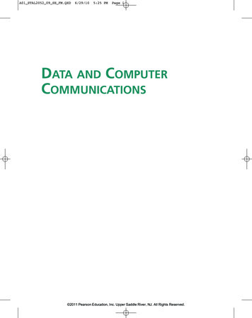
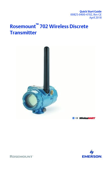
Noise immunity of digital signalsBroadband Access Wireless Communication Lab.7Department of Electrical and Computer EngineeringMichigan State University
Digital vs. Analog Communications (2) Noise immunity of digital signals – digital data can be recovered withoutany error as long as the distortion and noise are within limits. On the otherhand, for an analog message, even a slight distortion or interference in thewaveform will cause an error in the received signal.Regenerative repeaters––Based on this “noise immunity”, whentransporting a bit stream over a long distance, regenerative repeaters orrepeater stations are placed along the path of a digital system at distancesshort enough to ensure that noise and distortion remain within a limit. Theviability of regenerative repeaters is the main reason for the superiority ofdigital systems over analog ones.Every possible communication can be carried on with a minimum oftwo symbols, i.e., by using a proper binary sequence. In the last 20 years,digital communication gradually replace its analog competitors, and therevolution is now nearly complete.Broadband Access Wireless Communication Lab.8Department of Electrical and Computer EngineeringMichigan State University
Interface of Analog and Digital Systems-- A/D and D/A Conversion Sampling Theorem A meeting ground exists for analog and digital signals:conversion of analog signals to digital signals. The backbone that supportsthe interface is Shannon's Sampling Theorem, which states that if thehighest frequency in the signal spectrum is B (in hertz), then the signal canbe recovered from its samples, taken at a rate not less than 2B samplesper second.Quantization each sample is approximated, or round off to the nearestquantized level, the information is thus digitalized. The quantized signal isan approximation of the original one. We can improve the accuracy of thequantized signal to any desired degree by increasing the number of levels.Coding Source coding Convert the quantized signal into binary sequences. Channel coding Introduce redundancy in a controlled manner toovercome the effects of noise and interferences.Mapping Map binary sequence into symbols.Transmission Symbols are applied to a transmitter filter, which produces acontinuous signal for transmission over a continuous channel.Broadband Access Wireless Communication Lab.9Department of Electrical and Computer EngineeringMichigan State University
Examples of Wireless Communication Systems Codeless telephones --- use radio to connect a portable handset toa dedicated base station over a distance of a few tens of meters.Paging systems --- Communication systems that broadcast a pagefrom every base station in the network and send brief messages toa subscriber.Cellular telephone systems --- provide a wireless connection to thePSTN (Public Switched Telephone Network) for any user locationwithin the radio range of a system.Garage car openerRemote controllers for home entertainment equipmentHand-held walkie-talkiesWireless keyboard and mouseWireless Lan router and adapter .Broadband Access Wireless Communication Lab.10Department of Electrical and Computer EngineeringMichigan State University
Wireless Vs. Wireline Communications---- Challenges in Wireless Communication Systems Wireless channel Have time varying and multipath propagation properties.Communicate over a medium significantly less reliable than wiredphysical layer.Are unprotected from outside signals and interceptions. Multiuserinterference (MUI) is a significant problem in wireless communications.Has neither absolute nor readily observable boundaries outside ofwhich stations are known to be unable to receive network frames.User Mobility Destination address does not equal to a fixed destination location.Power management --- performance, interference lever and powerconsumption.Hand-off --- A mobile switches its serving base station while movingfrom cell to cell.Location management --- tracks the user’s movement, support usersroaming delivers calls to the user at its current location.Broadband Access Wireless Communication Lab.11Department of Electrical and Computer EngineeringMichigan State University
Trends on Wireless Communications Rapid growth In the last fewdecades, new and cheaperwireless services are emergingcontinuously, due to advances in: Digital signal processingDigital and RF circuit fabricationLarge scale circuit integrationDigital switching techniques - large scale deployment of radiocommunication networksConvergence of wireless andInternet ---- Broadbandcommunications 3G cellular and PCS networks WLAN networks Ad-hoc Networks (military)Broadband Access Wireless Communication Lab.12Department of Electrical and Computer EngineeringMichigan State University
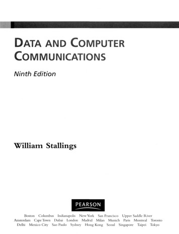
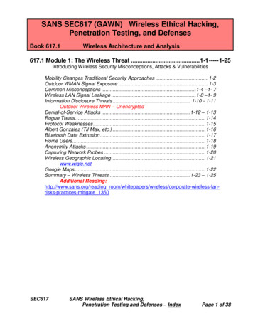
Cellular System ArchitecturePSTNMobileNode BCoreNetworkRNCMobileEmergencyServiceNode BCore NetworkRadio AccessBroadband Access Wireless Communication Lab.Internet13BackboneDepartment of Electrical and Computer EngineeringMichigan State University
Cellular System Architecture Radio Access: RF related signal processing and radio resourcemanagement. Mobile base station BSC or RNC MSC.Core Network: Main part is MSC (mobile switching center),performs user authentication, admission control, traffic control,roaming, billing, network support and maintenance etc.Backbone networks: Providing voice services (PSTN, PublicSwitched Telephone Network), data services (through Internet),and emergency services. Wireless networks need to be connectedto backbone networks to extend its service capabilities andgeographic coverage.Broadband Access Wireless Communication Lab.14Department of Electrical and Computer EngineeringMichigan State University
Multiple Access TechniquesBroadband Access Wireless Communication Lab.15Department of Electrical and Computer EngineeringMichigan State University
Multiple Access Techniques FDMA (Frequency Division Multiple Access) each user is allocated aunique frequency band or channel, no other user can share the samefrequency band.TDMA (Time Division Multiple Access) divides the radio spectrum into timeslots, and in each slot, only one user is allowed to either transmit orreceive.CDMA (Code Division Multiple Access) each user is assigned a specialcode sequence (signature) to modulate its message signal, all users areallowed to transmit over the same channel simultaneously andasynchronously.SDMA (Space Division Multiple Access) controls the radiated energy foreach user in space. SDMA serves different users by using spot beamantennas.Broadband Access Wireless Communication Lab.16Department of Electrical and Computer EngineeringMichigan State University
How a cellular telephone call is made? Receiving a call Turn on a cellular phoneThe cellular phone scan the control channels to determine the one with thestrongest signal, it then monitors the signal drops below a usable level. At hispoint, it starts to search of strongest base station again.If a phone call is placed to a mobile user, the MSC dispatches the request to allthe base stations in the system, the MIN (mobile identification number, i.e. themobile’s phone number) is broadcast as a paging message through the forwardcontrol channel.The mobile receives the signal through the base station it monitors andresponds by identifying itself through the reverse control channel.The base station informs the MSC of the handshake.The MSC instructs the base station to move the call to an unused voice channelwithin the cell.The base station signals the mobile to change frequencies to the unusedunused forward and reverse voice channel pair.The base station instructs the mobile phone to ring, thereby to instruct the userto answer the phone.Broadband Access Wireless Communication Lab.17Department of Electrical and Computer EngineeringMichigan State University
How a cellular phone call is made (continued) Initiating a call The mobile sends a call initiation request through the reverse control channel,with this the unit transmits its MIN, ESN (electronic serial number) and thephone number of the called party.Base station receives the request and sends it to the MSC.The MSC validates the request, making connection to the called party throughPSTN.The MSC instructs the base station and mobile user to move to an unusedforward and reverse voice channel pair.Roaming All cellular systems provide a service called roaming. This allows subscribers tooperate in service areas other than the one from which the service issubscribed.The MSC issues a global command every several minutes, asking allunregistered mobiles to report their subscription information.Mobiles report back upon receiving the request.If the mobile has roaming authorization for billing purpose, the MSC registersthe subscriber as a roamer.Broadband Access Wireless Communication Lab.18Department of Electrical and Computer EngineeringMichigan State University
Wireless System Evolution: Cellular PRSEDGECDMAIS-95CDMAoneIS-95B2G2.5GAMPS Advanced Mobile Phone SystemETACS European Total Access CommunicationSystemUnited States Digital CellularUSDCGlobal Systems for MobileGSMCDPD Cellular Digital Packet DataBroadband Access Wireless Communication Lab.GPRSEDGEUMTS WCDMA(3GPP)CDMA 20001X, 3X (3GPP2)3GGeneral Packet Radio ServiceEnhanced Data Rates for GSM EvolutionUMTS Universal Mobile Telecommunications Systemrd3GPP 3 Generation Partnership Project19Department of Electrical and Computer EngineeringMichigan State University
1G Wireless Systems Appeared in late 1970s and deployed in early 1980s.All based on analog techniques, all used FDMA and FMmodulation.System capacity is low. Data rate: 8 10 kbpsRepresentative Standards: AMPS: Advanced Mobile Phone System, developed by AT&T BellLabs in late 1970s. First deployed in 1983. The first AMPS systemused large cells and omni-directional base stationantennas, therefore, the number of users that can besupported was quite limited. AMPS is used all over the world andis esp. popular in US, South America, China and Australia. ETACS: European Total Access Communication Systems. Almostidentical to AMPS except that the channel bandwidth is scaled to25kHz instead of 30 kHz as in AMPS.Broadband Access Wireless Communication Lab.20Department of Electrical and Computer EngineeringMichigan State University
2G Wireless Systems: Characteristics Deployed in mid 1990s, 2G wireless systems all usedigital voice coding and digital modulation.Can provide advanced call capabilities and at least a 3times increase in overall system capacity.Was designed before the widespread of the Internet,mainly supported voice-centric services and limiteddate-service, like short messages, FAX,etc.Date rate: on the order of 10 kbpsBroadband Access Wireless Communication Lab.21Department of Electrical and Computer EngineeringMichigan State University
2G Wireless Systems: Representative Standards GSM (Global Systems for Mobile communications) A TDMA system, serves as the pan-European cellular service, providesa wide range of network service, including phone service, FAX, shortmessage service. Support 24.7kbps data rate.USDC IS-136 (United States Digital Cellular) A TDMA system which is compatible with AMPS, it supports moreusers (6 times) with improved performance. It shares the samefrequencies, frequency reuse plan and base stations as AMPS.Provides access to VPN, supports short messages. Support 48.6kbpsdata rate.IS-95 (United States Digital Cellular Standard ) A CDMA standard also designed to be compatible with AMPS throughusing of CDMA/AMPS dual mode phones and base stations. Capacityis 8 10 times that of AMPS. Support 14.4kbps data rate.Broadband Access Wireless Communication Lab.22Department of Electrical and Computer EngineeringMichigan State University
2.5G Wireless SystemCompared to 2G systems, 2.5G systems enables high speed data communications,provides continuous connection to internet. CDPD (Cellular Digital Packet Data), a data service for 1st and 2nd generation US cellularsystems without additional bandwidth requirement, packet channels are dynamically assigned toidle voice channels. Support 48.6kbps data rate as in IS-136. GPRS (General Packet Radio Service), based on GSM by allowing multiple slots of a GSMradio channel be dedicated to an individual user, promises data rate from 56 kbps to 114kbps--continuous connection to the Internet for mobile phone and computer users, easy access to VPN(Virtual Private Network). EDGE (Enhanced Data Rates for GSM Evolution), providing 384kbps rate by using improvedmodulation (8-PSK instead of GMSK in GSM) and relaxed error control. Also referred to asEGPRS. CDMA one (IS-95B): Providing high speed data access on a common CDMA radio channelby dedicating multiple orthogonal user channels for specific users or specific purposes. Support115.2kbps.Broadband Access Wireless Communication Lab.23Department of Electrical and Computer EngineeringMichigan State University
3G Wireless Systems: Features Features: High transmission rate and the support of multimediaservices. Multiple-megabit internet services, and simultaneous voice anddata access with multiple parties at the same time using a singlemobile handset.Date rate: around 2Mbps. Bandwidth: in the order of MHzSeamless global roaming: wireless access from anywhere onthe earth. Obviously, it will include the satellite networks.3GPP and 3GPP2 Worldwide standardization organizations established to gatherglobal expertise, participated by almost all the big companies. 3GPP: based on backward compatibility to GSM, IS-136, GPRS, EDGEetc.3GPP2: based on backward compatibility to IS-95, and CDMAone.Broadband Access Wireless Communication Lab.24Department of Electrical and Computer EngineeringMichigan State University
3G Wireless Systems: Challenges Impact of high transmission rate --- frequency selective fading High transmission rate implies that the signal bandwidth is much widerthan the coherence bandwidth of the channel, different frequencycomponents in the signal will experience different fading characteristic.Solution: Modulate each signal components onto a different subcarrierand send them over the channel in parallel, so that each componentwill experience flat fading. multicarrier systems.System capacity and user mobility Enlarged capacity and higher transmission rate requires more efficientdeployment of the available bandwidth, which implies that the systemneeds to be reused more often.Higher degree of frequency reuse implies more complex mobilemanagement.How to increase spectrum efficiency is the ultimate goal ofcommunication research.Broadband Access Wireless Communication Lab.25Department of Electrical and Computer EngineeringMichigan State University
3G Wireless Systems: Representative Standards 3GPP UMTS (Universal Mobile Telecommunications System) A widebandCDMA (5MHz) standard based on the network fundamentals ofGSM/EDGE, is designed to provide backward compatibility with GSM, IS136, GPRS and EDGE. Can support 2Mbps data rate. New RF equipmentneeded.3GPP2 CDMA 2000 3G 1X-3X Use one (same bandwidth as IS-95) orthree adjacent 1.25MHz channels (3-times bandwidth as that of IS-95) toprovide instantaneous packet data access at 144kbps or 2Mbps. Noadditional RF equipment needed, changes are all made in software orbaseband hardware.TD-SCDMA (Time-division Synchronous CDMA) A standard proposed byCATT (China Academy and Telecommunications Technology) andSiemens Corporation. Relies on the existing GSM infrastructure and allows3G data access by adding high data rate equipment (smart antennas) ateach GSM station. Support up to 384kbps of packet data.Broadband Access Wireless Communication Lab.26Department of Electrical and Computer EngineeringMichigan State University
Wireless Local Area Networks (WLANs) andPersonal Area Networks (PANs, Bluetooth) WLANs and PANs, provide broadband telecommunications access in thelocal exchange, driven by demand for broadband Internet access frombusiness and homes due to the rapid growth of the Internet.Provide high speed, high performance wireless connections betweencomputers and the wireless access points, between laptops, betweenlaptops and printers, scanners, video cameras and other electronics inlocal area or at home. Replace the cumbersome cords that connectdevices to one another.Operate at low power and license free spectrum, North America: IEEE 802.11x series, example: Wi-Fi.Europe: HIPERLAN/2Both IEEE 802.11a and HIPERLAN/2 support up to 54Mbps.Use spread spectrum and OFDM technologiesBluetooth: provides convenient and flexible low power short range wirelessconnections in personal area networks. First a manufacture, then extendedto an open standard.Broadband Access Wireless Communication Lab.27Department of Electrical and Computer EngineeringMichigan State University
Mobile Ad-Hoc Networks Cellular networks have a fixed infrastructure, in which each mobile accessthe network and communicating to other mobiles through the base station.That is, base station is the fixed infrastructure which performs centralizedadministration.Ad-Hoc networks are infrastructureless and have no fixed routers.Each node (mobile) in the ad-hoc network can set up as and play the roleof a base station in that it can transmit to and receive from other nodes inthe network.A node in an ad-hoc network to other nodes if they are within line-of-sight.Non-line-of-sight-nodes are called hidden nodes. Communication betweena pair of hidden nodes needs to hop over one or more intermediate nodes,in this sense, it is called multihop networks.A system with a fixed infrastructure is basically a two-hop system.Ad-hoc networks are highly dynamic and are generally used for militaryservices.Broadband Access Wireless Communication Lab.28Department of Electrical and Computer EngineeringMichigan State University
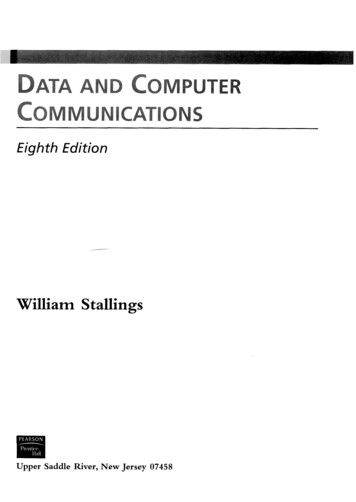
Conceptual Layers in a Wireless Network Physical layer --- involves the actual signaltransmission and reception over thepropagation channel.Datalink Link layer --- deals with signal atthe output of the base station receiver,performs radio resource management,power control, rate allocation, calladmission, error control etc.Networks layer: a protocol stack thatincludes handoff management, locationmanagement, traffic management andtraffic control.Application layer: communicating,distributed processes running in endsystems (hosts), e.g., e-mail, Web, P2P filesharing, instant messagingBroadband Access Wireless Communication Lab.29Application LayerNetwork LayerDate Link LayerPhysical LayerDepartment of Electrical and Computer EngineeringMichigan State University
Topics to be covered in this course In this course, we will focus on cellular networksand will discuss the following topics: Fundamentals of cellular communicationsCharacterization of the wireless channelTransmitter techniques for mobile radioReceiving techniques for fading dispersive channelsMultiple access techniquesMobile management in wireless networksWireless and wireline interworkingBroadband Access Wireless Communication Lab.30Department of Electrical and Computer EngineeringMichigan State University
Broadband Access Wireless Communication Lab. 6 Department of Electrical and Computer Engineering Michigan State University Digital vs. Analog Communications (1) Analog and Digital Signals Messages are digital or analog. Digital messages are constructed with a finite number