Transcription
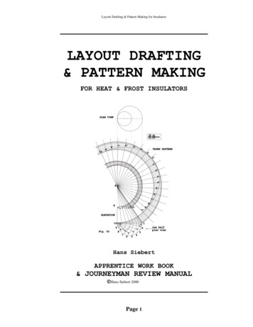
Layout Drafting & Pattern Making for InsulatorsLAYOUT DRAFTING& PATTERN MAKINGFOR HEAT & FROST INSULATORSHans SiebertAPPRENTICE WORK BOOK& JOURNEYMAN REVIEW MANUAL Hans Siebert-2000Page 1
Layout Drafting & Pattern Making for InsulatorsPrefaceThis book has been prepared as a text for use in Heat and Frost Insulatorapprenticeship classes. It explains basic methods of drawing patterns fordeveloping sheet metal and other types of protective covers commonlyproduced for wrap over insulation. The book does not attempt to teachfield work-practices or any application methods used in the trade.Learning how to crimp, bead, seam, rivet and apply materials is bestaccomplished on the job, not from studying a book.However, for thelimited purpose of pattern development, this book meets every requirementof an apprenticeship textbook and is, in addition, also well adapted forreference use by journeymen, foremen, and pre-fabrication workers engagedin the designing and/or laying out patterns.The instructions are easy to follow with numerous practical problems thatcanbecompletedstraightforwardlyandworked withoutelaboratecollections of tools or equipment. The subject-matter deals with commontrade problems and the specific methods of presenting the assignments arethe result of many years of teaching in apprenticeship classes as well aspractical experience gained in the asbestos worker trade.The format of the book assumes sequential completion of tasks, especiallyregarding the preparatory work of practicing drawing principles. For thenovice, later work in the book assumes knowledge gained in prior effort.For students with prior knowledge many of the projects can be completedwithout a drawn-out effort on the study of groundwork.The descriptions are clear and well organized and step-by-step. Theystimulate the student to think and reason on his or her own volition aswell as simplify the instructor's participation. The work is so plannedthat the student can work through assignments without arduous directionand tedious supervision. Numerous illustrative problems are distributedthroughout the text. The selected assignments and examples arerepresentative of the kind of problems a worker faces on the job and theyserve to enable the mechanic to apply knowledge to new-fangled anduncommon situations.Finally, no new material is to be found in this book. Although, I havedrawn all illustrations myself, the described projects have been scrapedtogether from various sources in the building trades, including frommanuscripts and books used in the asbestos workers, sheet metal workersand ironworkers trades. Additionally, ideas for the projects have beencollected from apprenticeship programs throughout the industry. Any andall such contributions are thankfully acknowledged.Hans SiebertOctober 2000Page 2
Layout Drafting & Pattern Making for InsulatorsTable of ContentsDrawing PrinciplesEquipment, Tools, Preparations5Practice Problems in DrawingBisect Straight LineErect PerpendicularsErect Perpendiculars (Method 2)Erect Perpendiculars (Method 3)Draw Parallel LineCircle PropertiesDraw TangentBisect AngleDraw Equilateral TriangleCopy an AngleCopy a TriangleCopy an Irregular FigureConstruct a Square with Side GivenConstruct a Pentagon (Method 1)Construct a Pentagon (Method 2)Construct a HexagonConstruct an Octagon (Method 1)Construct an Octagon (Method 2)Construct an Octagon (Method 3)Draw a Circle Through PointsFind Center of CircleDescribe Segment of CircleInscribe Triangle into CircleInscribe Circle into TriangleDraw an EllipseDraw an Approximate EllipseDraw an Approximate Ellipse (Method 2)Draw an Ellipse by Intersecting LinesDraw an Egg-shaped OvalDraw an Ellipse with Pencil and ThreadDraw a ParabolaDraw a HyperbolaDraw a SpiralDraw a HelixDivide a Straight Line into Equal Parts (Method 1)Divide a Straight Line into Equal Parts (Method 3334353637383940414243ContinuedPage 3
Layout Drafting & Pattern Making for InsulatorsPractice Problems in Pattern DevelopmentIntroduction to DevelopmentsClosed BoxOpen BoxSquare ovetail SeamMetal Over Tees (Field Method)Non-reducing Tee Layout90-Degree BendGores for Bends (Field Method)Gores for Bends (Development Method)Gores for Bends (Analytical Method)Non-reducing Lateral at any AngleReducing Tee at 90 DegreesReducing Lateral at any AngleConeTruncated Cone (Transition)SpheresLunes for Spheres (Head Gores)Lunes for Spherical Tank HeadCylindrical Tank with Rounded Head (Analytical Method)Rounded Head Lunes (Shortcut Method)Round Taper (Off Center)Round Taper (One Side Straight)35-Degree Conical End CapSquare to SquareSquare to RoundButterfly 868891929394959799Table of Decimal to Fraction Conversions100Table of Natural Trigonometric Functions101Practice Problems for Advanced Studies103-121Page 4
Layout Drafting & Pattern Making for InsulatorsGeometric ConstructionDRAWING PRINCIPLESDRAWING EQUIPMENTEquipment. The following list comprises the equipment required fora course in sheet-metal pattern drafting: Drawing board, 24" x 30",T-square, 30"; 45 triangle, 10”; 30 x 60 triangle, 10";architect's scale, 12"; 4H drawing pencil; pencil erasing rubber;thumb tacks; detail paper; also a set of drawing instrumentsconsisting of the following items: 5" dividers, 5 1/2" compasses,3" bow spacers, 3" bow pencil, ruling pen, bow pen and irregularcurves.Paper. The paper generally used for sheet-metal pattern drafting isknown as brown detail paper. However, for finished drawings, whitecraft paper is more suitable. It can be bought of almost any width,in large or small rolls, and is sold by the yard or pound. Thepaper should be of medium thickness, very strong and tough, becausea shop drawing is likely to be subjected to considerable roughusage.Pencils. For working drawings, full size details, etc., on craftpaper, a 4H pencil is quite satisfactory. For developing miterpatterns in which the greatest accuracy is required, a 5H pencil isgenerally used. The accuracy of drawings depends, in a greatmeasure, upon the manner in which the pencils are sharpened. Tosharpen the pencil, remove the wood from both ends by means of asharp knife, exposing about 3/8" of lead. One end should then besharpened to a round point, and the other to a chisel point or awedge-shaped end. This operation should be done with a fine file orpencil sharpener. For example, a strip of No. 0 sandpaper, 4" longand 3/4" wide, glued to a thin strip of wood, is quite serviceable.The chisel end of the pencil is used for drawing straight lines,and the conical point for free-hand sketching and markingdimensions. A soft pencil should never be used for drawing, becauseit becomes dull after drawing just a few lines. Soft pencils makeit difficult to draw fine, sharp lines and to keep the paper clean.Preparation of the Paper.The paper is fastened to the board with thumb-tacks. Care must betaken to have it lie perfectly flat on the board, so that it willcreate no wrinkles. To do this, proceed as follows: Place the longedge of the paper parallel with the long edge of the board, thepaper being within about three inches of the lower and left-handedge of the board. Insert a thumb-tack in the upper right-handPage 5
Layout Drafting & Pattern Making for Insulatorscorner and press it in until it is flush with the surface of thepaper. Next, place the left hand on the paper near the upperright-hand corner; then slide the hand toward the lower left-handcorner, removing all wrinkles, and insert a thumb tack as before.Lay the left hand on the middle of the sheet and slide it towardthe upper left-hand corner; holding it there, press in the thirdtack. Slide the hand from the center of the paper toward the lowerright-hand corner, and insert the fourth tack. This completes theoperation.PRACTICAL GEOMETRYIn presenting this subject to the student, no attempt has been madeto give a complete course in geometry. Rather, the selectedproblems are chosen to be of the greatest assistance to the patterndraftsman. They are composed of examples that are used in every-daypractice and are arranged in a logical order.Practical geometry is the science of geometry adapted to practicalpurposes. Theoretical demonstrations have been omitted. Everystudent, whose aim it is to become a proficient pattern draftsman,should have a fair knowledge of the subject. The problems on thesepages should be carefully studied and worked with great accuracy,as the technical skill acquired in the use of the drawinginstruments will be of great value in later work.Geometrical ProblemsWhen the problems herein given have been carefully studied, draweach problem, completing each step in the construction beforeproceeding to the next. All lines should be as sharp and fine to beconsistent with clearness.It is best to work the assignments in a sequential order becausesome of the later projects assume knowledge of skills, that havebeen mastered in preceding attempts.In the geometrical figures, except for occasional deviations, thegiven and required lines are shown in full heavy lines, and theconstruction in full light lines. The drawings on the instructionsheets do not always exactly reflect the specified dimensions,however, the distances within a drawing are proportional to them.This is due to the fact that drawings, manipulated on the sheets bya word processor, have been adjusted to conform to spacelimitations. Nevertheless, the assignments, when drawn, shouldreflect the exact dimensions stated in the problems.Preparation of Plates. The size of paper recommended for theproblems of this course is 15" x 20". The size of each plate is tobe 14" x 18", having a border-line all around 1/2" from the edge ofthe plate, leaving the space inside of the border line 13" x 17".Page 6
Layout Drafting & Pattern Making for InsulatorsDivide the plate into two equal parts by means of a horizontalline. Using the scale, divide the length of plate into three equalparts, as shown by the vertical lines. This divides the drawingplate into six rectangular spaces. The problems should be drawn asnear the center of each space as possible. See the followingexample in Fig. 0Fig. 0EXAMPLE OF COMPLETED SET OF DRAWINGSPage 7
Layout Drafting & Pattern Making for InsulatorsPractice Problems in DrawingN21OA21MFIG. 1HS2000Fig. 1. To bisect a straight line MN, or the arc of a circle MON.Let MN 3-1/4 inches long be the given line, which it is required tobisect. With centers M and N, and any radius greater than one-halfof MN, describe the arcs 1 and 2. Through the points ofintersection of these arcs draw a line, and the points ofintersection with the given line MN, and the arc MON, shown by OAwill give the required points.Page 8
Layout Drafting & Pattern Making for InsulatorsFig. 2. To erect a perpendicular from a given line. Draw theAB about 3-1/4 inches long. With the point of the compass onany radius greater than AB, describe an arc at 1. On B, withsame radius, describe the arc 2. Through the intersection ofand 2, draw the line EF. CE and/or CF will be the requiredperpendicular.Page 9lineA andthearcs 1
Layout Drafting & Pattern Making for Insulators756342ABCFIG. 3HS2000Fig. 3. To erect a perpendicular near the end of a given line. DrawAB 3-3/4 inches long. About 1/2 inch from B locate the point C,from which the perpendicular is to be erected. With C as center andwith any convenient radius, describe the arc 1-2. Using the sameradius, step off this distance from 1 to 3 and 3 to 4. Using anyradius with 3 and 4 as centers, describe arcs 5 and 6 intersectingeach other at 7. Draw a line from C through 7, which will give therequired perpendicular, at the given point C.Page 10
Layout Drafting & Pattern Making for InsulatorsHS2000F4m23EABCFig. 4Fig. 4. To erect a perpendicular at the end, of a given line. DrawAC, the given line, 3-3/4 inches long. Set the point of compass onA, and with any radius describe the arc B2. On B with the radiusAB, describe the arc 3 intersecting arc B2 at E. Through E drawline BF indefinitely; with radius BE, describe arc 4, intersectingline BF at m. Connect mA, which will be the perpendicular required.Page 11
Layout Drafting & Pattern Making for Insulators42A13BFIG. 5HS2000Fig. 5. To draw a line parallel to a given line. Draw AB 3-1/2inches long. Near the end of the line at 1, set the point of thecompass, and with a 2-inch radius, describe arc 2. With the sameradius on the point 3, describe the arc 4. Then a line drawntouching the arcs 2 and 4 will be parallel to AB.Page 12
Layout Drafting & Pattern Making for InsulatorsEFACBDFIG. 6HS2000Fig. 6. To draw a circle and its properties. Draw AB 3-3/4 incheslong. Bisect AB at C. With point of compass at C, and radius CA,describe the circumference of the circle. The diameter of a circleis any straight line drawn through the center to opposite points ofthe circumference as AB. The radius of a circle is any line as CAand DC, drawn from the center to any point in the circumference;two or more such lines are radii, the plural of radius. An arc of acircle is any part of the circumference as EG. The sector of acircle is the part of a circle included between the radii and thearc, which they intercept, as ACD. A segment of a circle is a partcut off by a chord, as EFG. A chord of a circle is a straight linejoining the extremities of an arc, but not passing through thecenter, as EF.Page 13
Layout Drafting & Pattern Making for InsulatorsCABDFig. 7HS2000Fig. 7. To draw a tangent from any given point on a circle. Withpoint of compass at A and radius AB, describe a circle 3-1/2 inchesin diameter. Through point B and center A draw a straight line. Aperpendicular (see prior task in Fig. 2) drawn through point B willgive the required tangent, as CD.Page 14
Layout Drafting & Pattern Making for Insulators3AC21BFig . 8H S 2000Fig. 8. To bisect a given angle. Draw the given angle ABC. With anyconvenient radius and B as center, describe the arcs 1 and 2. Withthe same or a larger radius and 1 and 2 as centers, describe arcsintersecting at 3. Draw a line from 3 to B, which divides the angleABC into two equal parts. (Note: This problem shows how to obtainthe miter line between the two parts of an elbow or sheet-metalmolding.)Page 15
Layout Drafting & Pattern Making for InsulatorsC21BAFig. 9HS2000Fig. 9. To draw an equilateral triangle, one side being given. DrawAB 2-3/4 inches long. With A as center and AB as radius, describearc 1. With B as center and the same radius, describe arc 2intersecting the former arc at C. Draw the lines BC and AC, and ABCis the required equilateral triangle.Page 16
Layout Drafting & Pattern Making for InsulatorsC1AB23G5EF4Fig . 10H S 2000Fig. 10. To construct an angle similar to a given angle. Let CABbe the given angle. With A as center and with any radius, describearc 1-2, touching both sides of the angle. Draw line EF equal toAB. With E as a center and radius A2 of the given angle, describearc 3-4. With 4 as center and radius 1-2, describe arc 5intersecting arc 3-4 at G. A line drawn from E through point Gcompletes the angle GEF, which is equal to BAC.Page 17
Layout Drafting & Pattern Making for InsulatorsCAB43512Fig . 11H S 2000Fig. 11. To draw a triangle equal to any given triangle. Draw thegiven triangle ABC and line 1-2 equal to AB. With the radius AC andthe center at 1, describe the arc 3. With the center at 2 and theradius BC, describe arc 4 intersecting arc 3 at 5. Draw lines 1-5and 2-5, which will give the required triangle equal to the giventriangle ABC.Page 18
Layout Drafting & Pattern Making for InsulatorsChDgnofABme12109745116183Fig . 122HS2000Fig. 12. To construct an irregular angular figure similar to agiven figure. Draw line AB 3-1/4 inches long and constructtrapezium ABCD. To copy this figure in exactly the same size as itis given, draw line 1-2 equal in length to AB. With A as center andAe as radius, describe arc ef. With the same radius and 1 ascenter, describe arc 3-4. With e as center, describe the arc g.With the same radius and 3 as center, describe arc 5 intersectingarc 4 at 6. Draw a line from 1 through 6, making 1-7 equal to AD.With B as center, describe arc mn. With the same radius and 2 ascenter, describe the arc 8-9. With m as center, describe arc h,cutting line BC at o. With the same radius and 8 as center,describe arc 10 intersecting arc 9 at 11. Draw line 2-12 throughpoint 11, and make it equal in length to BC. Draw line 7-12 tocomplete the trapezium similar to the given trapezium ABCD.Page 19
Layout Drafting & Pattern Making for Insulators43FG12CEDABFig. 13HS2000Fig. 13. To construct a square from a given side. Draw line AB3-1/2 inches, the length of the given side. With A as center and ABas radius, describe arc B-1 indefinitely. With the same radius andB. as center, describe the arc A-2, intersecting arc 1 at C. BisectAC at D through intersecting arcs at E. With C as center and radiusCD, describe arcs 3 and 4, intersecting arcs 1 and 2 at F and G. Tocomplete the square, connect AF, FG and GB.Page 20
Layout Drafting & Pattern Making for InsulatorsE43B1AD265CFig. 14HS2000Fig. 14. To construct a regular pentagon in a given circle. With Aas center and with the compasses set to 1-7/8 inches, describe thecircle BCDE. Draw the two diameters BD and EC perpendicular to eachother. Bisect the radius AB by the line passing through AB at 1.With 1 as center and 1-E as radius, describe the arc, locatingpoint 2. With E as center and the distance E-2 as radius, describean arc cutting the circumference of the circle at 3 and 4. Usingthe same radius with 3 and 4 as centers, describe the arcs 5 and 6.Connect points E-4-5-6-3, which completes the pentagon.Page 21
Layout Drafting & Pattern Making for Insulators342E1CAFig. 15BHS2000Fig. 15. To construct a pentagon from a given side. Let AB be thegiven side. With A as center and with the compasses set to 1-3/4inches, describe the semi-circle CEB. Divide CEB into five equalparts, and from A draw lines through the divisions 1-2-E. With ABas radius and E as center, describe the arc 3. With the same radiusand B as center, describe the arc 4. Draw the lines E-3, 3-4 and 4B to complete the figure.Page 22
Layout Drafting & Pattern Making for Insulators12ACB34Fig. 16HS2000Fig. 16. To construct a hexagon from a given side. Describe acircle with the radius AB 1-7/8 inches, which will be the length ofthe given side. Draw the diameter BC. With the radius AB and thecenters C-B, describe the arcs 1-2-3-4. Connect by straight linesC-1, 1-2, 2-B, B-3, 3-4 and 4-C, which completes the requiredhexagon.Page 23
Layout Drafting & Pattern Making for InsulatorsD128BCA37465EFig. 17HS2000Fig. 17. To inscribe an octagon within a given circle. With A ascenter, with the compasses set to 1-7/8 inches, describe the circle1-2-3-4-5-6-7-8. Let this be the given circle in which to inscribea regular octagon. Through the center, draw lines BC and DEperpendicular to each other, cutting the circumference of thecircle at 1-5 and 7-3. Bisect the angles DAB and DAC, and let thebisector of each angle meet the circumference at 2 and 8. Draw thediameters 8-4 and 2-6. Straight lines drawn from 1-2, 2-3, 3-4,etc., will form the required octagon.Page 24
Layout Drafting & Pattern Making for InsulatorsD67C24G58A31Fig. 18BHS2000Fig. 18. To inscribe an octagon within a given square. Draw line AB4 inches long, and construct the given square ABCD. Draw diagonallines DB and AC. With B as center and BG as radius, describe thearc 1-2. With the same radius and A,D and C as centers, describearcs 3-4, 5-6, 7-8. Straight lines drawn from 6-2, 2-8, 8-3, etc.,will complete the required octagon.Page 25
Layout Drafting & Pattern Making for InsulatorsDC91011835461271HS2000AB2Fig. 19Fig. 19. To construct an octagon, one side being given. Draw lineAB 1-1/4 inches long, which is the length of the given side. ExtendAB indefinitely, as shown by 1 and 2. From A and B erect indefiniteperpendiculars as AC and BD. With A and B as centers, using anyradius, draw the arcs 1-3 and 4-2. Bisect the angles 1-A-3 and 4B-2 by 5-A and 6-B. On these two lines set off A-7 and B-12, equalto AB. From 7 and 12 erect the perpendiculars 7-8 and 12-11, equalto AB. With 8 and 11 as centers and AB as radius, describe arcs9-10, intersecting perpendiculars AC and BD at 9 and 10. Connect8-9, 9-10 and 10-11, which completes the required octagon.Page 26
Layout Drafting & Pattern Making for InsulatorsGAEBCFFig. 20HS2000Fig. 20. To draw a circle through any three given points not in astraight line. Let CAB be the given points not in a straight line.Draw the lines CA and AB. Bisect the line CA by EF, as shown. Alsobisect AB by the line GF, and the intersection of the bisectinglines at F will be the center of the required circle. Then with Fas center and FB as radius, describe the circumference throughpoints ABC.Page 27
Layout Drafting & Pattern Making for Insulators8C5X961024B1A3HS20007Fig . 21Fig. 21. To find the center of a circle when the circumference isgiven. Let ABC be the given circle. From any point on the circle asB, with any radius, describe the arc 1-2. Then from the points Aand C, with the same radius, describe the intersecting arcs 3-4 and5-6. Through the points of intersection draw the lines 7-8 and9-10, which will meet in X. Then X will be the center of thecircle.Page 28
Layout Drafting & Pattern Making for InsulatorsGmBAPCnFig. 22HS2000Fig. 22. To describe the segment of a circle of any given chord andheight. Draw the line AB 3-3/4 inches long, which will be the givenchord. Draw the perpendicular mn indefinitely, and make Pm thegiven height 1-1/8 inches long. Connect mB and bisect mB by theline CG, intersecting the perpendicular mn at C. Then C will be thecenter from which to describe the segment AmB.Page 29
Layout Drafting & Pattern Making for InsulatorsACGFBFig. 23HS2000Fig. 23. To inscribe an equilateral triangle in a circle. Draw theline AB 3-3/4 inches long, which will be the diameter of the givencircle. With B as center and BC, the radius of the circle asradius, describe the arc FCG. To complete the inscribed triangle,connect by straight lines FA, AG and GF.Page 30
Layout Drafting & Pattern Making for InsulatorsCmBAFig . 24H S 2000Fig. 24. To inscribe a circle in a given triangle. Draw the line AB3-3/4 inches long. Make AC 3 inches, and CB 4 inches in length.Bisect the angles CAB and ACB. The intersection of the bisectors atm will be the center of the circle, which can be described,touching all three sides of the triangle. The sides AB, BC and CAwill be tangent to this circle.Page 31
Layout Drafting & Pattern Making for ig. 25HS2000Fig. 25. To draw an ellipse when the diameters are given, withoutusing centers. Draw the line 1-A 3-1/2 inches long, which will bethe required length. Bisect 1-A at C. Through C draw DE 2-1/4inches long, the required width. With C as center and C-1 and CE asradii, describe the outer and inner circles, respectively, asshown. Divide one-quarter of the outer circle into any convenientnumber of parts, in this case, into five, as shown by 1-2-3-4-5-6.Divide the one-quarter inner circle into the same number, as shownfrom 1’ to 6’. From the points on the smaller circle, drawhorizontal lines, and through the points on the larger circles,draw vertical lines. The points a, b, c, d, where the horizontaland vertical lines intersect, are points on the ellipse. Using anirregular curve, trace a line through the points thus obtained,completing one-quarter of the ellipse.Page 32
Layout Drafting & Pattern Making for Insulators498copA1m32EBFDG6H 75Fig . 26HS2000Fig. 26. To draw an approximate ellipse when length and width aregiven, using circular arcs. Draw the line AB 3-1/4 inches long.Bisect AB at m, and draw the width CD 2-1/8 inches long. On thelength AB, set off the width CD from B to 3, and divide the balance3A into three equal parts, as shown by 1, 2, 3. With m as centerand a radius equal to the length of two of these parts, describearcs cutting AB in E and F. With EF as radius and E and F ascenters, intersect arcs at 4 and 5. Draw lines from 4 through E andF as 4-6 and 4-7, and lines from 5 through EF as 5-8 and 5-9. With4 and 5 as centers and 5-C and 4-D as radii, describe the arcs GDHand OCP. With E and F as centers and radii equal to EA and FB,describe the arcs GAO and PBH, completing the ellipse.Page 33
Layout Drafting & Pattern Making for InsulatorsDOPGmAEBHFRCFig. 27SHS2000Fig. 27. To draw an approximate ellipse, the major and minor axesbeing given. For many purposes in sheet metal drawing, it issufficiently accurate to describe the ellipse by means of circulararcs, and where centers must be used in developing patterns forflaring articles. Draw the major diameter, AB, 3-7/8 inches long,and the minor diameter, CD, 3 inches in length. On the line CD layoff mF and mG, equal to the difference between the major and minordiameters. On the line AB lay off mE and mH equal to three-quartersof mG. Connect points FHGE, and extend the lines. With center E andradius EA, describe arc RAO. With center F and radius FD, describearc ODP. In a similar manner, describe arcs PBS and SCR fromcenters G and H. (Note: This is not a practical method when themajor diameter is more than twice the minor).Page 34
Layout Drafting & Pattern Making for InsulatorsCmD545433221nA23451BA’Fig . 28HS2000Fig. 28. To draw an ellipse by intersection of lines. Draw themajor axis AB 3-1/2 inches long, and the minor axis mA' 2-1/4inches. Through m parallel to line AB draw line CD. Frown points Aand B erect perpendiculars to line CD. Divide lines AC and DB intoa convenient number of equal parts; in this case, four, and drawlines from points 1, 2, 3, etc., to m. Divide An and nB into thesame number of equal parts, and draw lines from A' through thesepoints intersecting the similarly numbered lines drawn from thepoints on the line CA and DB. Through these points of intersection,trace the semi-ellipse AmB.Page 35
Layout Drafting & Pattern Making for InsulatorsmBACnHGFig. 29HS2000Fig. 29. To draw an egg-shaped oval with arcs of circles. With aradius of 1 3/8 inches and C as center, describe the circle AmBn.Through the center C, perpendicular to AB, draw the lice mn.Through n draw Bn and An indefinitely. On A and B as centers, withAB as radius, describe the arcs BH and AG. With n as center,describe the arc GH to complete the figure.Page 36
Layout Drafting & Pattern Making for InsulatorsCAmHGBDFig. 30HS2000Fig. 30. To draw an ellipse by means of a pencil and thread. DrawAB, the major axis, 3-3/4 inches long. Bisect AB at m. Through mdraw the perpendicular CD 2-1/2 inches long. Take Am one-half thelength of the major axis for radius, and with C as center, describethe-arc GH. Drive pins at C, G and H; then, tightly, tie a threadaround the three pins CGH. Remove the pin at C, and, placing apencil at this point, keeping the thread tightly stretched,describe the ellipse.Page 37
Layout Drafting & Pattern Making for ig. 31. To draw a parabola, having given the axis AB and thedouble ordinate FD. Draw AB 3-1/2 inches long, and FD perpendicularto AB, 4 inches long. Draw EF and CD parallel and equal to AB.Divide EF and BF into the same number of equal parts. From thedivisions on BF, draw lines parallel to the axis AB, and from thedivisions on EF, draw lines to the vertex A. The points ofintersection of these lines 1 and 1, 2 and 2, etc., are points onthe required curve through which it may be traced. In like-manner,obtain the opposite side.Page 38
Layout Drafting & Pattern Making for InsulatorsAMEC332211F123B3Fig. 3221DHS2000Fig. 32. To draw a hyperbola, the axis, a double ordinate and itsdistance from the vertex being given. Draw the double ordinate FD3-3/4 inches long. Perpendicular to FD, draw the axis BA 3-3/8inches long. On the line AB locate M 1-3/8 inches from the vertexA. Through M draw EC perpendicular to AB; then draw FE and DCperpendicular to FD, intersecting FE and DC in E and C. Divide FEand DC into the same number of equal parts, and from points 1, 2,3, etc., on FE and CD, draw lines to the vertex M. From points onFB and BD, draw lines to the vertex A. The intersection of theselines 1 and 1, 2 and 2, etc., will be points in the requiredhyperbola.Page 39
Layout Drafting & Pattern Making for Insulators324516A711109Fig . 338HS2000Fig. 33. To draw an equable spiral. Draw the line A6 4-5/8 incheslong. Bisect A6 at O, and with 0 as center and OA as radius,describe the circle A-3-6-9. Divide the circle into twelve equalparts, and to the points on the circumference draw radial linesfrom the center at 0. Divide AO into as many equal parts as thespiral is to have revolutions; in this case, two. Divide each spaceinto twelve equal parts, the same number of parts as there aredivisions in the circle. With O as center and O-1, 0-2, 0-3, O-4,etc., as radii, describe concentric arcs intersecting the similarlynumbered radial lines, as shown. Through the points of intersectionthus obtained, trace a curved line, completing the required spiral.(A spiral is easily drawn with a string attached to the center ofthe spiral and the drawing pencil. As the string winds around thepencil, it becomes shorter in length and, as the radius becomesshorter, a spiral is created.)Page 40
Layout Drafting & Pattern Making for . 348910 11 12 13 14 15 16CHS2000Fig. 34. The Helix. The Helix is a curve formed by a point movingaround a cylinder and at the same time advancing along the line ofits axis a fixed distance for each revolution. The
sharp knife, exposing about 3/8" of lead. One end should then be sharpened to a round point, and the other to a chisel point or a wedge-shaped end. This operation should be done with a fine file or pencil sharpener. For example, a strip of No. 0 sandpaper, 4" long and 3/4" w