Transcription
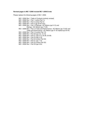
Model FSD-331Combination Fire Smoke DampersApplicationSteel Airfoil BladesUL555S Leakage Class IUL555 3 Hour Fire Resistance RatingModel FSD-331 is a high performance combination firesmoke damper with Class I leakage. High strength airfoilblades ensure the lowest resistance to airflow in HVACsystems with velocities to 4000 fpm (20.3 m/s) and pressuresup to 8 in. wg (2kPa). Model FSD-331 may be installedvertically or horizontally (with blades running horizontal) andis rated for airflow and leakage in either direction.RatingsUL555 Fire Resistance RatingFire Rating: 3 hoursDynamic Closure Rating: Actual ratings are size dependentMaximum Velocity: 4000 fpm (20.3 m/s)Maximum Pressure: 8 in. wg (2 kPa)UL555S Leakage RatingLeakage Class: IOperational Rating: Actual ratings are actuatordependentMaximum Velocity: 4000 fpm (20.3 m/s)Maximum Pressure: 8 in. wg (2 kPa)Maximum Temperature: 350 F (177 C) - depending onactuatorStandardOptionalFrame MaterialConstructionGalvanized steel-Frame MaterialThickness16 ga.(1.5mm)-Frame Type5 in. x 1 in.(127mm x 25mm)hat channel-Blade MaterialGalvanized steel-Blade MaterialThicknessDouble Skin 14 ga.(2mm) equivalent-Airfoil-Plated steel out ofairstream, concealedin jamb316SSBlade TypeLinkageAxle Bearings316SS-Axle MaterialPlated steel-Blade SealsSilicone-Jamb SealsStainless Steel-RRLRRL/OCI orFusible Link165 F(74 C)212 F (100 C),350 F (177 C)Closure DeviceClosure Temperature*Width and Height dimensions furnished approximately 1 4 in. (6mm)undersize in case of nominal sizing only. (Add sleeve thickness for overallsleeved damper dimension). Right hand drive is shown. Left hand isavailable upon request.Model FSD-331 meets the requirements for firedampers established by:National Fire Protection AssociationNFPA Standards 80, 90A, 92, 101 & 105IBC International Building CodesSee complete marking onproduct.UL 555 and UL 555SClassification R13317WxHMinimumSizeInchesmmMaximum SizeSingleSectionMultiple Section8x632 x 36 (V) or30 x 48 (H or V)120 x 96 (V) or120 x 96 (H)203 x 152813 x 1270 (V) or762 x 1219 (H or V)3048 x 2438 (V) or3048 x 2438 (H)Note: Maximum sizes are dependent on velocities and pressures.Features Frames are constructed with reinforced corners. Lowprofile head and sill are used on sizes less than 17 in.high (432mm). Blades are a double skin airfoil with full length structuralreinforcement.Installation instructions available at www.greenheck.co.in
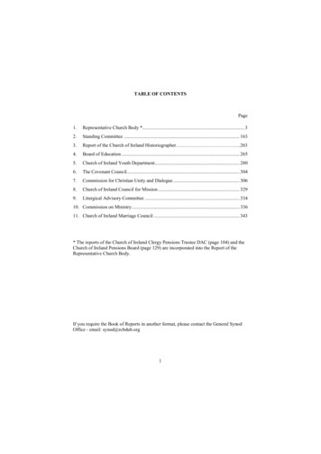
Options & Pressure Drop DataFSD-331Options Factory mounted accessories- POC Retaining angles- Quick connect breakaway connections- S & drive connections- TDF Flange Actuators: 24V, 230V Transitions : RLHRHPressure Drop DataThis pressure drop testing was conducted in accordance with AMCA Standard 500-D using the three configurationsshown. All data has been corrected to represent standard air at a density of .075 lb/ft3 (1.201 kg/m3).Actual pressure drop found in any HVAC system in a combination of many factors. This pressure drop information alongwith an analysis of other system influences should be used to estimate actual pressure losses for a damper installed in agiven HVAC system.AMCA Test FiguresFigure 5.3 illustrates a fully ducted damper. This configuration has the lowest pressure drop of the three testconfigurations because entrance and exit losses are minimized by straight duct runs upstream and downstream of thedamper.Figure 5.2 illustrates a ducted damper exhausting air into an open area. This configuration has a lower pressure dropthan Figure 5.5 because entrance losses are minimized by a straight duct run upstream of the damper.Figure 5.5 illustrates a plenum mounted damper.This configuration has the highest pressure5D6Ddrop because of extremelyhigh entrance and exit losses due to the sudden changes of area in the system.5D5D6D6DFigure 5.35D5D5DDDFigure 5.2Figure 5.54D4 (W)(W) (H)(H)3.143.144 (W) (H)3.14
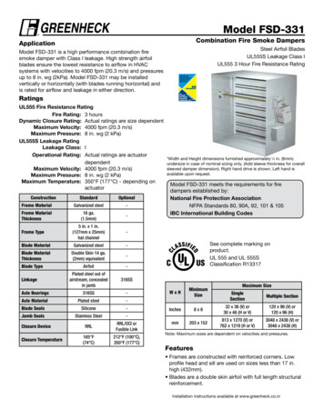
Pressure DropFSD-331AMCA Figure 5.25D4 (W) (H)3.14D12 in. x 12 in. (305mm x 305mm)VelocityPressure Drop(fpm)(in. 0.660.951.301.7024 in. x 24 in. (610mm x 610mm)VelocityPressure Drop(fpm)(in. wg)500100015002000250030003500400036in. x 36 in. (914mm x 914mm)VelocityPressure Drop(fpm)(in. 250030003500400012in. X 48 in. (305mm x 1219mm)VelocityPressure Drop(fpm)(in. 25003000350040000.010.050.120.210.330.480.650.8548 in. x 12 in. (1219mm x 305mm)VelocityPressure Drop(fpm)(in. 0.510.741.001.31AMCA Figure 5.35D6D5D12 in. x 12 in. (305mm x 305mm)Velocity (fpm)5001000150020002500300035004000Pressure Drop(in. wg)0.010.060.130.230.370.530.730.9524 in. x 24 in. (610mm x 610mm)Velocity (fpm)5001000150020002500300035004000Pressure Drop(in. wg)5D0.010.020.060.100.160.230.320.426D36in. x 36 in. (914mm x 914mm)5DVelocity (fpm)5001000150020002500300035004000Pressure Drop(in. wg)0.010.020.050.090.140.210.290.3812in. X 48 in. (305mm x 1219mm)48 in. x 12 in. (1219mm x 305mm)Pressure DropVelocity (fpm)(in. wg)5000.0110000.0315000.064 (W)0.11 (H)D200025000.183.14D 3000 4 (W) (H)0.253.14 0.34350040000.45Velocity (fpm)5001000150020002500300035004000Pressure Drop(in. wg)0.010.040.100.180.290.420.570.74AMCA Figure 5.512 in. x 12 in. (305mm x Pressure Drop(in. wg)0.040.180.420.751.171.682.292.0924 in. x 24 in. (610mm x Pressure Drop(in. wg)0.030.130.290.520.811.171.602.1436in. x 36 in. (914mm x Pressure Drop(in. wg)0.030.120.270.480.751.081.481.9312in. X 48 in. (305mm x 0Pressure Drop(in. wg)0.030.120.270.490.771.111.511.97Greenheck India Private Limited certifies that the model FSD-331shown herein is licensed to bear the AMCA seal. The ratings shownare based on tests and procedures performed in accordance withAMCA Publication 511 and comply with the requirements of theAMCA Certified Ratings Programs. The AMCA Certified RatingsSeal applies to air performance ratings only.48 in. x 12 in. (1219mm x Pressure Drop(in. wg)0.030.140.320.570.891.281.752.29
ARight hand drive is shownLeft hand drive available upon request(127mm)Sleeve LengthApplication DataFSD-331Actuators and AccessoriesSpace EnvelopesT*SExternally mounted actuators always require space outsideof the damper sleeve. The “S” dimension illustrates theclearance required for various available actuators.On damper less than 18 in. (457mm), actuators may alsorequire clearances above and/or below the sleeve. “B” and“T” dimensions are worst case clearance requirements forsome dampers less than 18 in. (457mm) high. All dampersizes under 18 in. (457mm) high do not require theseworst-case clearances. If space availability above or belowthe damper sleeve is limited, each damper size should beindividually evaluated.B*Actuator Type/ModelB*T*SWithRRL or RRL/OCIWithRRL or RRL/OCIPiggybackNoYesNA24 Volt ACFSTF24 (-S) Belimo711 16 in (195mm) 2 in. (13mm)6 in. (152mm)FSLF24-S Belimo7 16 in (195mm)06 in. (152mm)NA 2 in. (13mm)913 16 in (249mm)6 in. (152mm)9 in. (229mm) 2 in. (13mm)81 2 in (216mm)6 in. (152mm)NA 2 in. (13mm)913 16 in (249mm)6 in. (152mm)9 in. (229m)111FSNF24 (-S) Belimo1MS8104 Series Honeywell1MS8120 Series Honeywell1230 Volt ACFSLF230-S Belimo711 16 in (195mm)06 in. (152mm)NA 2 in. (13mm)9 16 in (249mm)6 in. (152mm)9 in. (229mm) 2 in. (13mm)81 2 in (216mm)6 in. (152mm)NA 2 in. (13mm)81 2 in (216mm)6 in. (152mm)NA 2 in. (13mm)9 16 in (249mm)6 in. (152mm)9 in. (229mm)FSNF230-S Belimo1MS4604 Series Honeywell1MS4X09 Series Honeywell1MS4620 Series Honeywell11313* For dampers 18 in. (457mm) or more in height these dimensions are 0 in.
Application DataFSD-331Damper Sleeve and Sideplate Dimensional DataThe drawings below and corresponding table show the position of the FSD-331 damper when mounted in a factorysleeve. the standard mounting locations provide enough space for the mounting of actuators, controls and allow spacefor installation of retaining angles and duct connections.The standard location of a damper mounted in a factory sleeve (“A” dimension) is shown below. The damper can bepositioned at other locations within a range of 6 in. (152mm) to 16 in. (406mm) for the “A” dimension."A" Dimensionin. (mm)1½ in. (38mm)maximumSleeveAll Dampers (RRL)Sleeve MaxSideplate7 16 in. (183)16 (406)63 16 (157)12 (305)16 (406)12 (305)3When Height is 11 in.(279) or less with RRLor RRL/OCI3¾ in.(95mm)Sleeve StdNOTE: Entire damper frame is not required to be installed within the wall. The damperblades, when closed should be contained within the wall.6 in.(152mm)11/2 in. max.VariesRHwnrequestSideplate5 3/8 in.(137mm)5 in.(127mm)ASleeve Length3 3/4 in.6 in.Varies5 3/8 in.T*5 in.SAASideplateLength**5 in.Sleeve LengthDamper Sizing InformationDampers larger than maximum single section size are supplied as a factory assembly of two or more sections of equalsize. The following figures show maximum damper section size and assembly configurations for multi-section dampers.Single SectionDouble SectionB*48 in.(1219mm)48 in.(1219mm)50 in.(1270mm)30 in. (762mm)30 in. (762mm)60 in. (1524mm)
Transitioned Damper DimensionsFSD-331When a fire/smoke damper is being used in conjunction with round ductwork, the FSD-331 can be supplied in a factorysleeve with round transitions on both ends of the sleeve. Dampers should be ordered to the duct dimensions. Drawingsbelow shows overall damper size.D* 2 in. (51mm) T s2 in. (51mm) Ts2 1/8 in.(54mm)D*16 in.(406mm)MinimumTYPE R*These dimensions are furnished approximately 1/4 in. (6mm) undersize, exceptround and oval dimensions which are approximately 1/8 in. (3mm) undersize.Ts (2)(Sleeve Thickness)SpecificationsCombination fire smoke dampers meeting the followingspecifications shall be furnished and installed whereshown on plans and/or as described in schedules.Dampers shall meet the requirements of NFPA (80, 90A,92, 101, and 105) and shall be tested, rated, and labeledin accordance with the latest edition of UL Standards555 and 555S. Dampers shall have a UL555 fire rating of3 hours and be of low leakage design qualified to UL555S,Leakage Class I.Each damper/actuator combination shall have a UL555Selevated temperature rating of 250 F (121 C) minimumand shall be operational and dynamic rated to operateat maximum design air flow at its installed location. Eachdamper shall be supplied with an appropriate actuatorinstalled by the damper manufacturer at the time ofdamper fabrication. Damper actuator shall be (specifierselect one of the following) electric type for 24 or 230 voltoperation.Damper blades shall be double skin airfoil type and shallhave an equivalent thickness of 14 ga. (2mm). Damperframe shall be galvanized steel formed into a structuralhat channel shape with reinforced corners. Bearings shallbe 316SS type rotating in extruded holes in the damperframe. Blade edge seals shall be silicone rubber designedto inflate and provide a tighter seal against leakage aspressure on either side of the damper increases. Jambseals shall be stainless steel compression type.Blades shall be completely symmetrical relative to theiraxle pivot point, presenting identical resistance to airflow ineither direction or pressure on either side of the damper.Damper must be rated for mounting vertically (with bladesrunning horizontal) and be UL555S rated for leakageand airflow in either direction through the damper. Eachdamper shall be supplied with a 165 F (74 C) RRL. Testingand ratings to be in accordance with AMCA Standard500‑D.The basis of design is Greenheck model FSD-331.Greenheck India: 201-202, 2nd Floor, Landmark Cyber Park, Sector 67, GurgaonCopyright 2020 Greenheck India Private LimitedFSD-331 Rev. 14 December 2020
Model FSD-331 is a high performance combination fire smoke damper with Class I leakage. High strength airfoil blades ensure the lowest resistance to airflow in HVAC systems with velocities to 4000 fpm (20.3 m/s) and pressures up to 8 in. wg (2kPa). Model FSD-331 may be installed vertically or horizontally (with blades running horizontal) and