Transcription
SYSTEMS ENGINEERINGDESIGN PROJECTENPM 643, Fall 2006InstructorDr. M AustinAuthorsAtul Mehta & Felipe LeiteENPM643Fall 2006
ENPM 643 – Fall ’06Parking Lot Occupancy Tracking SystemTABLE OF CONTENTSSection1OVERVIEW OF THE PROJECT. 31.11.21.31.41.51.62PagePURPOSE . 3ROLES AND RESPONSIBILITIES . 3INTRODUCTION . 3DEFINITIONS. 4ASSUMPTIONS AND LIMITATIONS . 4REFERENCE MATERIAL . 4UML MODELS. 52.12.22.32.42.52.62.72.8DEPLOYMENT DIAGRAM . 5USE CASE SUMMARY . 6CAR ARRIVING . 7CAR LEAVING . 10DISPLAY PARKING SPACE AVAILABILITY. 12SYSTEM PRIVILEGES/UTILITIES . 13UPDATE/NEW USER DATABASE . 15GENERATE REPORT . 173REQUIREMENTS/ GOALS & SCENARIOS. 194DESIGN ANALYSIS & VALIDATION . 255CONCLUSION . 292
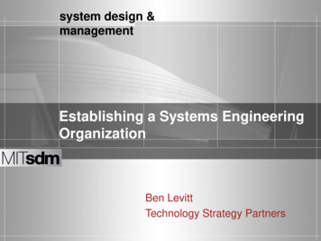
ENPM 643 – Fall ’06Parking Lot Occupancy Tracking System11.1OVERVIEW OF THE PROJECTPurposeThe goal of this project was to take a parking lot control system from requirement generation,through model generation and validation. This document describes the process taken a presents theresulting data.1.2Roles and ResponsibilitiesThe project team is formed by the following students: Atul Mehta and Felipe Leite. Sinceall team members have the same experience and expertise designing systems, the work wasdivided equally and assigned arbitrarily.1.3IntroductionFor our project, we have decided to design a system that can be deployed in existingparking structures which would provide information about available parking spaces to driverstrying to access the facility. The system will include software, sensors and the networkingcomponents.The installation of permanent sensors in each parking space will provide lot owners withconstant and accurate information on parking lot occupancy. This allows them to keep the lot atfull capacity and serve customers better. Figure 1 shows the building parking lot that we will bedesigning for. It has 72 parking spaces where 8 are handicap, 4 are for the building staff and theremaining 60 are available for regular lot users. In addition, a list of members provided to thesystem by the building owner will be used to grant or not access to the facility.Figure 1 - Parking Lot Layout3
ENPM 643 – Fall ’06Parking Lot Occupancy Tracking SystemThe system will make use of electronic signs to give drivers, information regardingparking availability before they enter the facility. Once inside, color coded LED displays willlead motorists to the vacant spaces. Parking spaces can be made unavailable by the buildingmanager bypassing the sensors. This and other configuration options will be made availablethrough a GUI interface.1.4Definitions1.4.1Parking LotThe parking lot consists of one entrance and 1 exit. There are 72 parking spaces with 8being handicap and 4 being reserved for building staff.1.4.2EntranceThe entrance consists of a gate, a display showing the precise number of availableparking spaces, a tag reader. The tag reader is activated as soon as the car is within range.1.4.3ExitThe exit consists of a gate and an induction loop that is behind the gate to detect when acar approaches the gate.1.51.6[1]Assumptions and Limitations Every parking space can be reached from any entrance. Every exit can be reached from each parking space. No entrances are convertible to exits and vice versa. Building manager assigns a unique tag to each authorized car. Tag number and vehicle information is stored in a database maintained by the buildingmanager. Emergency situations (e.g. fire) will not be considered here.Reference MaterialJ Magee and J Kramer, “Concurrency State Models and JAVA Programming,” JohnWiley & Sons Ltd., 2nd Edition, 20064
ENPM 643 – Fall ’06Parking Lot Occupancy Tracking System22.1UML MODELSDeployment DiagramThe Parking Lot Occupancy Tracking system can be divided into sub-components as seen in thedeployment diagram shown above. The Parking Lot Occupancy Tracking system consists of a parkinggate interface, manager interface, parking lot controller system interface, parking sensor system interface,display interface and network interface.Parking Gate InterfaceThis subsystem is triggered as soon as a commuter/car arrives near the parking gate. The scannerscans the tag. The unit controller in the interface checks the authorization of the commuter with thedatabase of the system. If authorization confirmed the unit controller triggers the gate to open and let thecommuter in the parking lot. If authorization fails, the gate is not opened.5
ENPM 643 – Fall ’06Parking Lot Occupancy Tracking SystemManager InterfaceManager interface system is an indirect component to the system. The owner/manager of thesystem plays the role of the manager interface. The system is automated and hence the only role of themanager during the running system is to start/stop, add/delete/edit details of commuters and generatesreport from the system database. The manager however has the privileges of changing the systemconfiguration and display manually entered messages on the display board during maintenance or systemtroubleshooting.Parking Lot Controller InterfaceParking lot controller interface consist of servers and a database that records all the events thesystem goes through the day. The controller receives and sends information to the unit controllers as wellas displays the information on the main display board.Parking Sensor System InterfaceParking sensor system interface consist of sensors, unit controllers, unit display boards and backup battery for the system. This system is triggered when a car parks or leaves the parking lot. When acommuter parks the car in the parking lot, the sensor detects the action and sends information to the unitcontroller. The unit controller receives the information and triggers the unit display board to record theaction and also send the information to the main controller interface to display the action on the maindisplay board.Display InterfaceDisplay interface displays the status of the system. It has a unit controller, which records theinformation and displays the message through the display board. It also consists of a backup battery forthe smooth running of the system.2.2Use Case Summary6
ENPM 643 – Fall ’06Parking Lot Occupancy Tracking System2.3Car ArrivingUse Case NarrativeUse-Case Name:Car ArrivingPrimary Actor:Car/DriverOther Actors:NoneDescription:This use case describes the event of the system tracking when a car arrives atthe parking lotAssumptions:Parking Lot OpenPrecondition:Car must have a parking lot tagInitiation/Trigger:The use case is initiated when the car approaches the entrance gateTypical Course OfEvents /Dialog:Actor ActionSystem ResponseStep 1: Car approaches gateStep 2: The system detects the car tagand checks with may database forauthorization.Step 3: The car is authorized and thesystem responds by opening the gate.Step 4: The car drivesthrough the gate.Step 5: The system closes the gateonce the car is through.Step 6: The car parks in anavailable space.Step 7: The system detects car.Step 8: The space status is updatedwithin the system.Alternate Courses:Alt-Step 3: If the car access is not authorized, an error message isdisplayed to inform the outcome that the access has been deniedConclusion:This use case concludes when the parking space status is updatedPost Condition:Parking space status is updated from vacant to occupied7
ENPM 643 – Fall ’06Parking Lot Occupancy Tracking SystemActivity Diagram8
ENPM 643 – Fall ’06Parking Lot Occupancy Tracking SystemSequence Diagram9
ENPM 643 – Fall ’06Parking Lot Occupancy Tracking System2.4Car LeavingUse Case NarrativeUse-Case Name:Car LeavingPrimary Actor:Car/DriverOther Actors:NoneDescription:This use case describes the event of the system tracking when a car leaves theparking lotAssumptions:Parking Lot OpenPrecondition:Car is inside the parking lotInitiation/Trigger:The use case is initiated when the car approaches the exit gateTypical Course OfEvents /Dialog:Actor ActionSystem ResponseStep 1: Car approaches theexit gateStep 2: The system detects the car bythe exit gateStep 3: The system sends a signal forthe exit gate to openStep 4: The exit gate opensStep 5: The car leaves theparking lot premisesStep 6: The exit gate closesAlternate Courses:N/AConclusion:This use case concludes when the exit gate closesPost Condition:The car is no longer within the parking lot limits10
ENPM 643 – Fall ’06Parking Lot Occupancy Tracking SystemActivity& Sequence Diagrams11
ENPM 643 – Fall ’06Parking Lot Occupancy Tracking System2.5Display Parking Space AvailabilityUse Case NarrativeUse-Case Name:Display Parking Space AvailabilityPrimary Actor:DisplayOther Actors:NoneDescription:This use case describes the event of the system updating the informationdisplayed by the parking lot entranceAssumptions:Parking lot open and display onPrecondition:NoneInitiation/Trigger:The use case is initiated when the parking lot opensTypical Course OfEvents /Dialog:Actor ActionSystem ResponseStep 1: The system initializes thedisplayStep 2: Displayacknowledges initializationStep 3: The system sends informationto the displayStep 4: Information isdisplayedStep 5: The system waits a presetamount of time and goes back to Step3Alternate Courses:Alt Step 5 If system disable the loop is terminatedConclusion:This use case concludes when the system is disabledPost Condition:The up-to-date information on available parking spaces is displayedActivity Diagram12
ENPM 643 – Fall ’06Parking Lot Occupancy Tracking System2.6System Privileges/UtilitiesUse Case NarrativeUse-Case Name:System Privileges/UtilitiesPrimary Actor:Manager/OwnerOther Actors:NoneDescription:This use case describes the possible system priveleges available to theparking lot owner.Assumptions:NAPrecondition:Manager must have the access password to the systemInitiation/Trigger:The manager enters the password to get access to the system.Typical Course OfEvents /Dialog:Actor ActionStep 1: Owner enters password to get access to the system.Step 2: Owner is authorized and has a choice of three options. (a/b/c)Step 3: The Owner selects the option. (a/b/c)Step 4.a: Ownerselects system on/off.Step 4.b: Ownerselects parking spaceto be altered, madeavailable/unavailableStep 4.c: Ownerenters messagemanually for thedisplay board.Step 5.a: Systemturned on/offStep 5.b: Parkingspace is altered.Step 5.c: Only theentered message isdisplayed on theboard.Alternate Courses:Alt-Step 2: Owner is not authorized and is unable to take any action onthe system.Conclusion:This use case concluded when system turned on/off or space altered ormessage is displayed.Post Condition:System on/off or Space altered or Message displayed.13
ENPM 643 – Fall ’06Parking Lot Occupancy Tracking SystemActivity Diagram14
ENPM 643 – Fall ’06Parking Lot Occupancy Tracking System2.7Update/New user databaseUse-Case Name:Update/New member tablePrimary Actor:ManagerOther Actors:NoneDescription:This use case describes the event of adding/removing/editing the accesspermission of a parking lot member.Assumptions:System on.Precondition:Manager authorized to access database.Initiation/Trigger:Manager enters details to be searched.Typical Course OfEvents /Dialog:Actor ActionStep 1: Manager gets access to the database.Step 2: Manager enters commuter details to search in the database.Step 3: Database shows the result in the form of commuter detailspresent/absent.Step 4.a: Managerenters details for thenew commuter in thedatabase.Step 4.b: Manager selects the commuterdetails to delete/update.Step 5a: Database isupdated by the newdetails entered.Step 5.b.1: Theselected commutergets deleted from thesystem database.Step 5.b.2: Managerselects details to beupdated for thecommuter.Step 6: Managerissues a new tag forthe new commuter.Step 6.b.1Theassociated tag getsdeactivated.Step 6.b.2: Details ofthe commuter getsupdated in systemdatabase.Conclusion:This use case concluded when system database is updated in the formof new- edited or deleted details of the commuter.Post Condition:Database is updated by the action.15
ENPM 643 – Fall ’06Parking Lot Occupancy Tracking SystemActivity Diagram16
ENPM 643 – Fall ’06Parking Lot Occupancy Tracking System2.8Generate ReportUse-Case Name:Generate ReportPrimary Actor:ManagerOther Actors:NoneDescription:This use case describes the event of creating a report based on theinformation collected by the system.Assumptions:System on.Precondition:Manager authorized to access database.Initiation/Trigger:Manager enters details to be searched.Typical Course OfEvents /Dialog:Actor ActionStep 1: Manager gets access to the database.Step 2: Manager selects information to generate the report.Step 3.a: Manager selectsinformation of commuter forreport.Step 3.b: Manager selects systeminformation for report.Step 4.a: Report generatedon the basis of theinformation in the database.Step 4.b.1:Manager opts formaintenancereport.Step 4.b.2:Manager opts forsystemperformance reportStep 6: Manager issues anew tag for the newcommuter.Step 6.b.1:Maintenancereport generated.Step 6.b.2:Performance reportgeneratedConclusion:This use case concluded when system creates a report on therequested option by the manager.Post Condition:Report from the database is generated.17
ENPM 643 – Fall ’06Parking Lot Occupancy Tracking SystemActivity Diagram18
ENPM 643 – Fall ’06Parking Lot Occupancy Tracking System3REQUIREMENTS/ GOALS & SCENARIOS.3.1 Goals and ScenariosThe use case describes all that can happen in the achievement of the system objective. Use Casesdrive the requirements engineering phase of development. The various Goals and Scenarioscritical to the system are depicted below ‘Goal 1: Operators must be able to edit and send messages to Display BoardsScenario 1.1: Operator will send messages from the system to the display board.Scenario 1.2: Operator wants to compose a new message that is not available in the list.Goal 2: There must be an on/off button at the control centerScenario 2.1: Emergency shut down required for maintenance.Scenario 2.2: Control center to be evacuated in case of fire etcGoal 3: Operators must be able to stop displaying current message on Display Boards.Scenario 3.1: A higher priority message or warning could be waiting to be displayed.Scenario 3.2: Displayed signs would no longer be valid.Goal 4: The Display Board must be “all weather proof”Scenario 4.1: Display board will be installed in outdoors as well as indoors.Scenario 4.2: Display board will be installed in far south as well as far northScenario 4.3: There is likelihood of snow, rain; heavy winds etc (should be sturdy enough towithstand adverse conditions)Goal 5: There must be an indicator showing the status of the active Display BoardScenario 5.1: System sends a message to the display board but the display board wasdisconnected.19
ENPM 643 – Fall ’06Parking Lot Occupancy Tracking SystemScenario 5.2: Display board out of service for maintenance.Scenario 5.3: Network or hardware failure on remote site.Goal 6: The system must store all information about every activity performed at eachworkstation.Scenario 6.1: Administrator wants to check the logs for specific information.Scenario 6.2: Periodic reports to be generated to check system performance.Goal 7: The system must be secureScenario 7.1: Unauthorized person tries to login.Scenario 7.2: Operator tries to change system settings, which he is not authorized to.Goal 8: The display board/sensor system must have backup powerScenario 8.1: Power failure occurs.Scenario 8.2: Power cable is broken due to accident.Goal 9: The sensor must be capable of detecting any vehicleScenario 9.1: Vehicle might be small in dimensions.Scenario 9.2: Vehicle might be parked wrong.Goal 12: The system must be capable of reporting any system failure to the manager.Scenario 12.1: The system is not displaying information.Scenario 12.2: The sensor is unable to recognize vehicles parked.20
ENPM 643 – Fall ’06Parking Lot Occupancy Tracking System3.2 Requirements:1. The system must contain a database.1.1. The database should contain all the information about the commuters.1.2 The database must allow retrieval and addition of information.2. The system must allow only the authorized users to enter the parking lot.2.1 The entrance gate control unit should open after the authorization of the commuter.2.2 The entrance sensor should verify the authorization through the database.3. The system must display parking space availability.3.1 The system should display the number of occupied spaces.3.2 The system should display the number of vacant spaces.3.3 The system should display messages from the manager during special instances.3.4 The message should take less than 10 seconds from the control center to the displayboards.3.5 The system should display message on the display board for 3 minutes unless anduntil stated otherwise.4. The system must receive a confirmation message for every message sent on the display screen.5. The system must have three parking spaces available.5.1 The system should have open parking spaces.5.2 The system should have handicap parking spaces.5.3 The system should security/service parking spaces.6. The system should have individual display boards for all parking spaces.6.1 The display boards must display green light for available spaces.21
ENPM 643 – Fall ’06Parking Lot Occupancy Tracking System6.2 The display boards must display red light for unavailable spaces.6.2 The display boards must display blue light for handicap parking spaces.7. The system must receive and send information to and from the unit controllers.7.1 The unit controller must receive information from sensors.7.2 The unit controller must display information on individual display boards.7.3 The unit controller must send information to control system.8. The system should have an indicator to indicate the status of display boards.8.1 The system must have red color indicator for inactive display, green color indicator asactive display board, and orange color to indicate a hardware failure of the displayboard.8.2 Every display board must send feedback to the control center every 5 seconds todisplay it as alive.9. The system should recognize the parked vehicle.9.1 The system sensor must recognize the parked vehicle irrespective of its size.9.2 The system sensor must recognize and report wrongly parked vehicle.10. The system should allow for redefining the parking spaces.10.1 The system must allow altering the parking spaces in case of maintenance.11. The system should allow the user to take over during troubleshooting11.1 The system must allow user to take over during system/sub-system failure.11.2 The system must allow user to create/edit messages on main display board.11.3 The system must allow user control while maintenance process.12. The control center shall have a single button to turn off the system.12.1 The button shall be a physical button present on the computer of the operator.22
ENPM 643 – Fall ’06Parking Lot Occupancy Tracking System12.2 The button shall have an LED on its side indicating the status of the system.12.3 The button shall have a clearly marked sign of system shut down.13. The control center shall have security.13.1 The control center shall have role based security system.13.2 Role in the control center shall include supervisor, maintenance and operator.13.3 The system shall have a counter for number of attempts.3.3 Requirements Mapping:SUBCOMPONENTS:1. Parking Gate2. Parking Space3. Manager Interface4. Display5. ControllerUML DIAGRAMS1. 2.3- Car Arriving2. 2.4- Car Leaving3. 2.5- Display Parking Space Availability4. 2.6- System Privileges/Utilities5. 2.7- Update/New user database6. 2.8- Generate Report23
ENPM 643 – Fall ’06Parking Lot Occupancy Tracking SystemREQUIREMENTSASSOCIATED COMPONENTUML DIAGRAMSREQ 1.0Controller, Parking gate,2.3, 2.7, 2.8REQ 2.0Controller, Parking gate2.3, 2.7REQ 3.0Manager interface, Display2.6REQ 4.0Controller, Display2.5REQ 5.0Display, Parking space2.3, 2.5,2.6REQ 6.0Parking space2.3, 2.4REQ 7.0Controller, Parking space, Display2.3, 2.5REQ 8.0Controller2.3REQ 9.0Parking space2.3, 2.5REQ 10.0Manager interface, Parking space2.6REQ 11.0Manager interface, Display2.6REQ 12.0Manager interface, Controller2.6REQ 13.0Manager interface2.624
ENPM 643 – Fall ’06Parking Lot Occupancy Tracking System4DESIGN ANALYSIS & VALIDATIONThe UML models are very helpful at hashing out all the different subcomponents of thesystem and their interaction. However, when creating the UML diagrams, the system designermay inadvertently create states that are never reached or legal transitions that if taken would putthe system in a deadlock. These design mistakes are not usually identified and corrected until thesoftware is being implemented or out on the field making the mistakes hard and costly to fix.UMLLTSAJavaFigure 2 - Verification & Validation FlowWith that situation in mind, we decidedto implement the design flow shown in Figure 2- Verification & Validation Flow. First the UMLwas created as described in section 2. Based onthe UML sequence diagram an LTSA model iscreated to check for potential deadlock orunreachable states. Once the parking lotcontroller design is complete, it was thenimplemented using Java to further verify itscoherence and to validate the interaction withthe external actors (e.g. car/driver).The car arriving sequence diagram(Figure 3 - Car Arriving Sequence Diagram) wascreated using the Argo shareware. Using that asa starting point and making use of LTSA-MSCplug-in, we came up with the high levelsequence of messages (Figure 4 - hSMC View)and the subcomponents interaction (Figure 5 Trace View).25Figure 3 - Car Arriving Sequence Diagram
ENPM 643 – Fall ’06Parking Lot Occupancy Tracking SystemFigure 5 - Trace ViewFigure 4 - hSMC ViewWith the views above generated, the LTSA tool was able to create a textual notation ofthe system also known as FSP or Finite State Process. Once the FSP is created, we were able tocheck our model for safety and progress. The safety check looks for states with no outgoingtransitions, which are potential deadlocks in the system. The progress check, also called liveness,this check verifies that whatever state a system is in, it is always the case that a specified actionwill eventually be executed. Both checks passed for our design. The resulting FSP model forsubcomponents as well as the architecture is shown below.Figure 6 - Parking Space Sensor Model26Figure 7 - Car Model
ENPM 643 – Fall ’06Parking Lot Occupancy Tracking SystemFigure 8 - Gate ModelFigure 9 - System Behavior ModelThe architecture model above was used to animate and check the behavior of the overallsystem. Figure 10 - Animation of Parking Lot Controller shows a captured image of the LTSA toolanimator window. The list on the right presents all possible transitions. However, the greencheck mark indicates the valid transitions from the state the system is in. That way the model canbe traversed from state to state to make sure the model behaves as expected. The animator wasused to test a group of scenarios against the model and the outcome was verified.Figure 10 - Animation of Parking Lot Controller27
ENPM 643 – Fall ’06Parking Lot Occupancy Tracking SystemThe last step in our flow was to validate the interaction between the parking lot controller and theactors external to the system. To do that, a Java applet was created where classes were created to emulateeach actor and the parking lot controller was implemented in a class of itself. The screenshot, Figure 11 Parking Lot Java Applet, is of the resulting applet.Figure 11 - Parking Lot Java Applet28
ENPM 643 – Fall ’06Parking Lot Occupancy Tracking System5CONCLUSIONFor this project, the goal was to take the idea of an occupancy aware parking lotthrough the design process as far as possible given the time and resources. At first the systemdetails were hashed out through the use of use case scenarios. These scenarios were then furtherrefined and modeled using UML diagrams. These first steps are widely applied during the designprocess of systems. For this project however, we decided to validate the UML models using awell defined and repeatable process rather than the usual model review meetings with teammembers approach. The method used was based on composing joint sets of transition statemachines using the FSP language and then check for unexpected behavior using a set of tools.Due to time constraints, we decided to go through the validation and verification flowwith the Car Arriving use case only. The exercise was successful and we were able to actuallyimplement part of the system at a higher level, using Java, to simulate its behavior. The availabletools out there, such as LTSA, are very helpful at discovering hidden potential paths within themodels and verifying that they work as intended. However, it is best suited for small size systemsat the present moment and need to be further developed before mainstream adoption is possible.One important feature would be the support for creating a library of low level models that couldbe reused over and over as building blocks for creating models of larger systems.29
Manager Interface Manager interface system is an indirect component to the system. The owner/manager of the system plays the role of the manager interface. The system is automated and hence the only role of the manager during the running system is to start/stop, add/delete/edit details of commuters and ge