Transcription
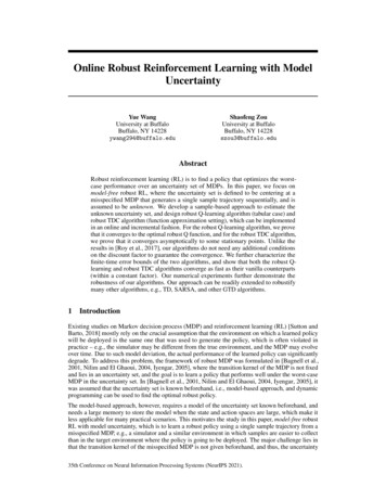
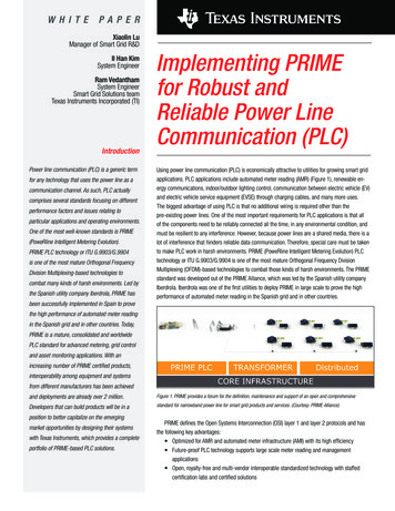
W H I T EPA P E RXiaolin LuManager of Smart Grid R&DIl Han KimSystem EngineerRam VedanthamSystem EngineerSmart Grid Solutions teamTexas Instruments Incorporated (TI)IntroductionPower line communication (PLC) is a generic termfor any technology that uses the power line as acommunication channel. As such, PLC actuallycomprises several standards focusing on differentperformance factors and issues relating toparticular applications and operating environments.One of the most well-known standards is PRIME(PoweRline Intelligent Metering Evolution).PRIME PLC technology or ITU G.9903/G.9904is one of the most mature Orthogonal FrequencyDivision Multiplexing-based technologies tocombat many kinds of harsh environments. Led bythe Spanish utility company Iberdrola, PRIME hasImplementing PRIMEfor Robust andReliable Power LineCommunication (PLC)Using power line communication (PLC) is economically attractive to utilities for growing smart gridapplications. PLC applications include automated meter reading (AMR) (Figure 1), renewable energy communications, indoor/outdoor lighting control, communication between electric vehicle (EV)and electric vehicle service equipment (EVSE) through charging cables, and many more uses.The biggest advantage of using PLC is that no additional wiring is required other than thepre-existing power lines. One of the most important requirements for PLC applications is that allof the components need to be reliably connected all the time, in any environmental condition, andmust be resilient to any interference. However, because power lines are a shared media, there is alot of interference that hinders reliable data communication. Therefore, special care must be takento make PLC work in harsh environments. PRIME (PoweRline Intelligent Metering Evolution) PLCtechnology or ITU G.9903/G.9904 is one of the most mature Orthogonal Frequency DivisionMultiplexing (OFDM)-based technologies to combat those kinds of harsh environments. The PRIMEstandard was developed out of the PRIME Alliance, which was led by the Spanish utility companyIberdrola. Iberdrola was one of the first utilities to deploy PRIME in large scale to prove the highperformance of automated meter reading in the Spanish grid and in other countries.been successfully implemented in Spain to provethe high performance of automated meter readingin the Spanish grid and in other countries. Today,PRIME is a mature, consolidated and worldwidePLC standard for advanced metering, grid controland asset monitoring applications. With anincreasing number of PRIME certified products,interoperability among equipment and systemsfrom different manufacturers has been achievedand deployments are already over 2 million.Figure 1. PRIME provides a forum for the definition, maintenance and support of an open and comprehensiveDevelopers that can build products will be in astandard for narrowband power line for smart grid products and services. (Courtesy: PRIME Alliance)position to better capitalize on the emergingmarket opportunities by designing their systemswith Texas Instruments, which provides a completeportfolio of PRIME-based PLC solutions.PRIME defines the Open Systems Interconnection (OSI) layer 1 and layer 2 protocols and hasthe following key advantages: Optimized for AMR and automated meter infrastructure (AMI) with its high efficiency Future-proof PLC technology supports large scale meter reading and managementapplications Open, royalty-free and multi-vendor interoperable standardized technology with staffedcertification labs and certified solutions
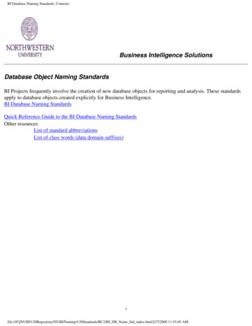
2Texas Instruments Millions of electrical meters armed with this PLC technology are being installed in the fieldand other countries, making it one of the most mature OFDM solutions The long Cyclic Prefix (CP) length in ISO layer 1 enables it to easily combat the frequency-selectivechannels Can be seamlessly integrated with either IPv6 or IEC61334-4-32 link layer to support COSEM/DLMSapplications Supports automated network formation with “tree” topology Addresses security and data privacyPRIME communication is bi-directional with an effective data rate of 21-128Kbps in the CENELEC-A band.The most recent PRIME standard to be released is version 1.4 and covers the frequency band from CENELEC-A(regulated in Europe) to the full FCC/ARIB band (3kHz – 490kHz) to provide a higher data rate: 40Kbps-1Mbps.Support for IPv6 enables PRIME to converge to IPv4 and IPv6 networks in an efficient manner so no additionalrouter is needed to run on IP network.PRIME OFDM modulation provides high resiliency to interference and attenuation. PRIME devices (calledservice nodes) automatically form a “tree” type network topology when plugged into the power line and aremanaged by a centralized “root” of the “tree” called a base node (BN) following PRIME MAC (media accesscontrol) protocols.Several factors impact PRIME PLC performance, including line noise, impedance and frequency-selectivechannels. At the network level, a developer must consider the number of nodes connected to the BN, the numberof levels from the “leaf” node to the “root” node, the reliability of the switch node, locations and length of the lowvoltage lines in order to run a reliable automated meter reading and control application.Factors impairingphysical performanceNoise has been the most studied factor in PLC systems. Since power lines are a shared medium, they have allkinds of electric devices connected to them so there can be significant noise impacting the system performance.The two prevalent noises are periodic impulsive noise (PIN) synchronous to 50Hz or 60Hz mains and narrowbandinterference (NI). Time domain noise taken in the field from the Spanish grid (Figure 2) shows noise bursts every10 ms ( 1/100Hz). Special care is needed to handle this kind of impulse noise with forward error correction,interleaving, etc. The PRIME specification defines interleaver to protect burst errors caused by impulse noise.Figure 2. Time domain noise trace (8-bit ADC) at secondary substation (SS) in the Spanish low voltage grid.Implementing PRIME for Robust and Reliable Power Line Communication (PLC)July 2013
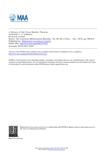
Texas Instruments 3Time-varying line impedance is another factor in low voltage (LV) grids. The PRIME Alliance Technical WorkingGroup has performed impedance measurements in various places across Spain [4]. Figure 3 shows one of theLV impedances measured at certain secondary substations (SS) in the CENELEC-A band. Impedance changes from0.1ohm to 1.5ohm relative to the frequency. This is because multiple other devices are plugged into the power line,which lowers the line impedance significantly. Different colors in the figure mean that impedanceis changing across the AC mains cycle and also shows that line impedance is increasing across thefrequency band.PRIME specifications define a Line Impedance Stabilization Network (LISN) by modifying the original LISN definedin CENELEC EN 50065-1 to reflect very-low line impedance conditions [5]. The effective impedance is 2ohm andPRIME specifies 1 Vrms (120 dBuV) injection over 2ohm load, which is a unique feature that is different from otherPLC specifications. This can be used to define minimum performance requirements in this small impedance.Figure 3. Impedance at the SS in the Spanish electricity grid.Frequency-selective channels are another factor typically impacting PLC performance. Power line channels arenormally frequency selective because of line impedance and channel delay due to distance. Modeling of PLC channels has been addressed using ABCD parameter and transmission line theory [6]. The frequency selectiveness of thepower line channel measured at one of the substations in the Spanish grid is shown in Figure 4. The calculated rootmean square (RMS) delay spread is 23.2µs. Since PRIME cyclic prefix (CP) length is 192µs, which can handle largedelay spreads [2], PRIME is therefore extremely resilient to frequency-selective channels.Figure 4. Channel profile at the substation in the Spanish electricity grid.Implementing PRIME for Robust and Reliable Power Line Communication (PLC)July 2013
4Texas InstrumentsSalient featuresof PRIME MACPRIME is a synchronous network, where the BN sends periodic beacons at every sub-frame time interval. Thenodes that forward packets to other nodes that cannot directly reach the BN are called switch nodes. These nodesare promoted by the BN during the registration process of nodes that directly cannot reach the BN. The switchnodes also transmit beacons in a periodic fashion in a multiple of the number of sub-frames. The topology createdby the PRIME network is “tree” type with the “root” being the BN. The route formation occurs naturally during thenode registration, based on the distance of the node and beacons transmitted by the BN or the switch node. Thereis no notion of periodic route maintenance and the routes formed by the “tree” during node registration processare maintained as long as the nodes are registered. The topology formed by the PRIME network can potentiallyspan multiple levels depending on the proximity of the farthest nodes to the BN and the channel characteristicsof the nodes as discussed in previous section.The BN also transmits periodic control frames to every node in the network, called “keep-alive” frames, tomonitor the nodes that are currently connected to the network. When a node receives a keep-alive frame from theBN – ALV B – it responds with keep-alive frame response, also known as ALV S. There is a notion of keep-alivetimeout maintained at the BN for each of the nodes. If an ALV B is not received within a keep-alive timeout, thenode considers itself to be unregistered to the BN and starts the re-registration process. Similarly, if the BN doesnot receive an ALV S frame from the node within the timeout, it removes the node from the registered list,causing the eventual deregistration of the node (due to lack of ALV B) and will trigger a re-registration process.In addition to the control frame transmission, there is a MAC-level error recovery mechanism calledAutomatic Repeat reQuest (ARQ) that is applied to any data packet transmission. The ARQ mechanism inPRIME is end-to-end, with only the source node can repeat a particular data transmission, in the event of a lackof acknowledgement from the final destination node. Note that the final destination node can potentially beseveral levels away from the source node. The MAC ARQ timeout is used by the source node to triggerre-transmission of unacknowledged frames. In addition, if a negative-acknowledgement is received, the sourcenode will use this information to retransmit the frame. Control frames such as promotion, registration andconnection establishment frames are subject to a similar end-to-end retry mechanism that uses a differentparameter for control retry timeout and the number of attempts before declaring the node to be unregisteredto the service node.Table 1 illustrates the key MAC layer features of the PRIME standard.MAC FunctionsPRIMETopologyTreeNetwork formationBeacon discovery, Automatic promotionMulti-hop routingYesKeep-alive monitoringYesConnection managementYesMedium accessCSMA/CAARQSelective ARQ end-to-endSecurity128-AES in CBCLink adaptationPRMAggregationOptional in Switch NodeTable 1. Overview of MAC features in PRIME.Implementing PRIME for Robust and Reliable Power Line Communication (PLC)July 2013
Texas Instruments 5PRIME certificationand deploymentPRIME has been successfully deployed in various harsh environments across Spain with millions of units andmultiple vendors. Before the devices are deployed, PRIME certification needs to be performed. There are twothird-party PRIME certification labs in Spain to perform the PRIME certification: KEMA and Tecnalia. TI was oneof the first semiconductor vendors to achieve the independent PRIME certification and currently has a testingfacility in Dallas to perform pre-certification for customers using TI’s PRIME solution (i.e., pre-certification wasconducted in TI’s labs before applying for the official certification.) As an example, Iberdrola has installed 1.3 millionPRIME-enabled smart meters by multiple e-Meter vendors as of August 2013. Those smart meters are connectedto secondary substations in locations representative for various environments and installation scenarios: urban,suburban and rural; dense and disperse; industrial and residential areas. All of the secondary substations weremonitored and analyzed before entering the production environment.Along with the deployment, a set of tools and lessons learned were developed that are applicable for any futuresmart meter deployments. These firsthand experiences are helpful for other utility companies who are currentlyengaged in or planning future smart grid and smart meter deployments. The model deployed in Castellon will beextended to other grids all over the world. Iberdrola continues its deployment at approximately 1 million new smartmeters per year and expects to maintain that pace through 2018.PRIME Standardbeyond v1.3.6Within the PRIME Technical Working Group, there have been significant efforts to improve system performance ofPRIME version 1.3.6, such as adding a set of new modes called “robust modes”, extending the frequency coverageup to 500kHz to achieve higher data rates, and adding new components in MAC for securities. The addition ofrobust modes in the CENELEC-A band gives more reliability in communication at lower data rates (i.e. 5Kbps and10Kbps). The PRIME Technical Working Group performed extensive channel measurements to validate theperformance of PRIME robust modes. Two robust modes are DBPSK ¼ repetition and DQPSK ¼ repetitionith longer preambles ( 8.192ms) for protection from power line impulse noise. These robust modes enablewith communication across the medium voltage (MV) to low voltage (LV) transformers. One of the unique featuresof the PRIME robust modes in comparison to similar technologies such as ITU G.9903/G3 and IEEE P1901.2 isthat the repetition is done at the OFDM symbol level instead of the bit level.Table 2 shows the new parameters defined in PRIME robust modes.ParameterRobust PRIME (OFDM System)Sampling frequency250kHzIFFT length512Carrier spacing488.28125HzCP length192 µsModulation sizeDBPSK/DQPSK/D8PSK/robust DBPSK/robust DQPSKPreamble length8.192msForward error correctionRate ½ convolutional code symbol repetition by 4Data rate5, 10, 21,42,64,84,128KbpsBand plan42-89kHzMACPRIME Standard MAC with enhancement for ROBO rates supportConvergence layerIEC61334-4-32/IPV6Metering applicationDLMS/COSEM, IPTable 2. PRIME parameters with newly defined robust mode.Implementing PRIME for Robust and Reliable Power Line Communication (PLC)July 2013
6Texas InstrumentsIn addition to more robust modulation schemes, the PRIME alliance has recently focused on scalability andubiquitous access by providing the IPv6 convergence layer. This IPv6 convergence layer provides an efficientmethod for transferring IPv6 frames over the PRIME network between the BN and the service nodes, or from anexternal network to the PRIME network. Both service nodes and BN support the standard IPv6 protocol [7] as wellas IPv6 addressing architecture [8] and global unicast IPv6 addresses, link local IPv6 addresses, and multicastIPv6 addresses as described in [8]. Packets within the PRIME sub-network are routed according to Node Identifier(NID), which is based on a combination of service node’s local connection identifier (LNID) and switch identifier(SID). At the convergence sub-layer, the BN maintains a mapping of IPv6 unicast addresses to the EUI-48 of eachservice node to perform address resolution. Other service nodes can query the BN to resolve an IPv6 address intoEUI-48 address. Optionally, UDP/IPv6 addresses may be compressed, as part of the connection establishmentphase. The PRIME specification describes one such approach for header compression of IPv6 packets knownas LOWPAN IPHC1, as defined in RFC 6282[9]. Additional compression techniques may include not transmittingthe link local IPv6 addresses for service nodes, which can be derived from a combination of service nodes’LNID and SID.Bandwidth extension to 500kHz also gives higher data rates up to 1Mbps for applications such as automotivepilot wire communication, LED lighting communication, etc. PRIME FCC/ARIB technology also incorporates therobust modes and longer preambles for reliable communication.ParameterPRIME Band Extension (OFDM System)Sampling frequency1MHzIFFT length2048Carrier spacing488.28125HzCP length192µsModulation sizeDBPSK/DQPSK/D8PSK/robust DBPSK/robust DQPSKPreamble length8.192msForward error correctionRate ½ convolutional code symbol repetition by 4Data rate40, 80, 168, 336, 512, 672, 1024KbpsBand plan42-472kHzTable 3. PRIME parameters with band extension to FCC/ARIB bandIn searching for the most appropriate PLC technology, Europe and many other countries such as Poland,Mexico, Indonesia, and so on. have begun their evaluation by characterizing how well PRIME serves under noisyoperating conditions in those regions. Taking into account those considerations, developers that can build productswill be in a position to better capitalize on the emerging market opportunities by designing their systems with ICsfrom Texas Instruments, which provides a complete portfolio of PRIME-based PLC solutions.Industry-leadingfield expertiseand innovationIn order to better understand the issues that arise with PLC in real-world networks across countries and regions,TI has performed extensive PRIME field testing worldwide to measure how varying operating environments impactsignal performance and robustness. Especially for grids in Indonesia and Mexico, PRIME signals were able toreliably travel 500m distances in direct low voltage connections without any assistance from intermediate switchnodes with 40Kbps throughput. With PRIME robust modes, 700m distances are achieved with 5Kbps without anyswitch nodes in between. In addition to TI PRIME field tests, many countries worldwide developed interoperablePRIME solutions and field tests with numerous nodes. In 2009, for example, MAC and PHY interoperability testswere performed in Spain, and are now massively deployed with 100,000 meters.Implementing PRIME for Robust and Reliable Power Line Communication (PLC)July 2013
Texas Instruments 7Figure 5. TI has performed extensive PRIME field testing worldwide to measure how varying operating environments impactsignal performance and robustness. The field tests covered a comprehensive variety of operating environments, topologies,distances and test times to verify that PRIME links could communicate under dynamically changing operating conditions.TI has also extensively partnered with customers in lab stress tests, which are performed for Iberdrola to gauge thesystem performance of different meter manufacturers. Among the many stress lab tests, “Test 7” is of particularimportance because it attempts to re-create the worst-case field conditions with 350 meters and multiple levels,and compares the network performance of various vendors. The performance metrics of key importance are themeter connectivity during network bring-up and during long-cycle reading, and the meter reading percentageduring long-cycle reading.Through those tests, TI gained a better understanding of what is required for a robust PLC solution that isreliable, scalable and cost-effective. TI has collected various channel modeling data and contributed to thedevelopment of the PRIME Technical Working Group channel measurements campaigns such as impedancemeasurements, channel measurements and noise measurements by providing measurement tools and methods.Channel models play a key role in enabling developers to create technology that can address the particularcharacteristics of a channel under a variety of operating conditions. For example, researchers have developedthorough and complete models of the channel characteristics for wireless communication. These modelsenable the industry as a whole to provide consistent and reliable wireless products. Without such models, theperformance, robustness and interoperability of wireless products would be compromised. TI is at the forefrontof research to achieve the level of understanding of PRIME PLC technology required to ensure a smooth adoptionand migration to power line-based communication.As a leader in PLC technology, TI continues to aggressively identify and solve problems that arise as thenumerous PLC standards mature. With its advanced field testing, TI has acquired an intimate knowledge of thespecific requirements for PLC in each country and region. TI is continuously bringing higher performance andimproved robustness to PLC technology. TI is a global company equipped to handle technology variations aroundthe world and provide the volume production these applications will require. TI is also unique in its ability tosupport so many applications beyond the utility meter.For more information about TI’s PRIME PLC technology and solutions, visit www.ti.com/PRIME-wp or contactyour local sales representative.Implementing PRIME for Robust and Reliable Power Line Communication (PLC)July 2013
8Texas InstrumentsTI’s smart gridsolutionsResourcesWith millions of energy meter ICs shipped over the past decade, Texas Instruments is the global systems providerfor innovative, secure, economical and future-proof solutions for the worldwide smart grid. TI offers the industry’sbroadest smart grid portfolio of metrology expertise, application processors, communication systems, wirelessconnectivity and analog components in readily available silicon, with advanced software, tools and support forcompliant solutions in grid infrastructure, utility metering and home or building automation. Learn more atwww.ti.com/smartgrid-wp.IEEE Smart Grid Communications (SmartGridComm) 2012Performance Results from 100,000 PRIME Smart Meters Deployment in Spain, A. Sendín, I. Berganza, A.Arzuaga, A. Pulkkinen, I.H. Kim, Tainan City, Taiwan, November 2012.IEEE Smart Grid Communications (SmartGridComm) 2011PRIME on-field deployment. First summary of results and discussion, I. Berganza, A. Sendín, A. Arzuaga, M.Sharma, B. Varadarajan, Brussels, Belgium, October 2011.IEEE Smart Grid Communications (SmartGridComm) 2010PRIME interoperability tests and results from field, A. Arzuaga, I. Berganza, A. Sendín, M. Sharma, B. Varadarajan,Gaitersburg, Maryland, USA, October 2010.References[1] M. Nassar, A. Dabak, I. H. Kim, T. Pande, and B. L. Evans, “Cyclostationary noise modeling in narrowbandpowerline communication for smart grid applications,” International Conference on Acoustics, Speech, andSignal Processing, Kyoto, Japan[2] M. Nassar, J. Lin, Y. Mortazavi, A. Dabak, I. H. Kim, and B. L. Evans, “Local utility powerline communicationsin the 3-500kHz band: channel impairments, noise, and standards,” IEEE Signal Proc. Mag., to appear[3] B. Varadarajan, I. H. Kim, A. Dabak, D. Rieken, and G. Gregg, “Empirical measurements of the low-frequencypower-line communications channel in rural North America,” International Symposium on Power LineCommunications and Its Applications (ISPLC), pp.463-467, 3-6 April 2011.[4] PRIME Alliance – Technical Working Group, “PRIME Specification”, version 1.3.6, Nov 2011, available:http://www.prime-alliance.org (May 2012).[5] EN 50065-1:2011, “Signaling in low-voltage electrical installations in the frequency range 3 kHz – 148.5 kHz– Part 1: General requirements, frequency bands and electromagnetic disturbances”, CENELEC, April 2011.[6] A. Dabak, I. H. Kim, B. Varadarajan, and T. Pande, ”Channel modeling for MV/LV AMI applications in thefrequency range 500kHz,” Workshop on Power Line Communications, Arnhem, The Netherlands, 2011.[7] Neighbor Discovery for IP Version 6 (IPv6), RFC 2461, Standards Track.[8] IP Version 6 Addressing Architecture, RFC 4291, Standards Track.[9] Compression Format for IPv6 Datagrams over IEEE 802.15.4-Based Networks, RFC 6282,Internet Engineering Task Force (IETF), Standards Track.[1][2][3] provide detailed spectro-temporal noise characterization over a frequency range 0 - 500 kHz.Important Notice: The products and services of Texas Instruments Incorporated and its subsidiaries described herein are sold subject to TI’s standard terms and conditions of sale.Customers are advised to obtain the most current and complete information about TI products and services before placing orders. TI assumes no liability for applications assistance,customer’s applications or product designs, software performance, or infringement of patents. The publication of information regarding any other company’s products or services doesnot constitute TI’s approval, warranty or endorsement thereof.The platform bar and are trademarks of Texas Instruments.All other trademarks are the property of their respective owners. 2013 Texas Instruments IncorporatedE010208SLYY038
IMPORTANT NOTICETexas Instruments Incorporated and its subsidiaries (TI) reserve the right to make corrections, enhancements, improvements and otherchanges to its semiconductor products and services per JESD46, latest issue, and to discontinue any product or service per JESD48, latestissue. Buyers should obtain the latest relevant information before placing orders and should verify that such information is current andcomplete. All semiconductor products (also referred to herein as “components”) are sold subject to TI’s terms and conditions of salesupplied at the time of order acknowledgment.TI warrants performance of its components to the specifications applicable at the time of sale, in accordance with the warranty in TI’s termsand conditions of sale of semiconductor products. Testing and other quality control techniques are used to the extent TI deems necessaryto support this warranty. Except where mandated by applicable law, testing of all parameters of each component is not necessarilyperformed.TI assumes no liability for applications assistance or the design of Buyers’ products. Buyers are responsible for their products andapplications using TI components. To minimize the risks associated with Buyers’ products and applications, Buyers should provideadequate design and operating safeguards.TI does not warrant or represent that any license, either express or implied, is granted under any patent right, copyright, mask work right, orother intellectual property right relating to any combination, machine, or process in which TI components or services are used. Informationpublished by TI regarding third-party products or services does not constitute a license to use such products or services or a warranty orendorsement thereof. Use of such information may require a license from a third party under the patents or other intellectual property of thethird party, or a license from TI under the patents or other intellectual property of TI.Reproduction of significant portions of TI information in TI data books or data sheets is permissible only if reproduction is without alterationand is accompanied by all associated warranties, conditions, limitations, and notices. TI is not responsible or liable for such altereddocumentation. Information of third parties may be subject to additional restrictions.Resale of TI components or services with statements different from or beyond the parameters stated by TI for that component or servicevoids all express and any implied warranties for the associated TI component or service and is an unfair and deceptive business practice.TI is not responsible or liable for any such statements.Buyer acknowledges and agrees that it is solely responsible for compliance with all legal, regulatory and safety-related requirementsconcerning its products, and any use of TI components in its applications, notwithstanding any applications-related information or supportthat may be provided by TI. Buyer represents and agrees that it has all the necessary expertise to create and implement safeguards whichanticipate dangerous consequences of failures, monitor failures and their consequences, lessen the likelihood of failures that might causeharm and take appropriate remedial actions. Buyer will fully indemnify TI and its representatives against any damages arising out of the useof any TI components in safety-critical applications.In some cases, TI components may be promoted specifically to facilitate safety-related applications. With such components, TI’s goal is tohelp enable customers to design and create their own end-product solutions that meet applicable functional safety standards andrequirements. Nonetheless, such components are subject to these terms.No TI components are authorized for use in FDA Class III (or similar life-critical medical equipment) unless authorized officers of the partieshave executed a special agreement specifically governing such use.Only those TI components which TI has specifically designated as military grade or “enhanced plastic” are designed and intended for use inmilitary/aerospace applications or environments. Buyer acknowledges and agrees that any military or aerospace use of TI componentswhich have not been so designated is solely at the Buyer's risk, and that Buyer is solely responsible for compliance with all legal andregulatory requirements in connection with such use.TI has specifically designated certain components as meeting ISO/TS16949 requirements, mainly for automotive use. In any case of use ofnon-designated products, TI will not be responsible for any failure to meet dioAutomotive and fier.ti.comCommunications and Telecomwww.ti.com/communicationsData Convertersdataconverter.ti.comComputers and Peripheralswww.ti.com/computersDLP Productswww.dlp.comConsumer ergy and Lightingwww.ti.com/energyClo
ergy communications, indoor/outdoor lighting control, communication between electric vehicle (EV) and electric vehicle service equipment (EVSE) through charging cables, and many more uses. The biggest advantage of using PLC is that no additional wi

![Algorithms AppendixI:ProofbyInduction[Sp’16]](/img/13/98-induction.jpg)