Transcription
This Tecumseh Manual is a free downloadfromwww.allotment-garden.orgTecumseh TC Series 2 cycle engines manual
TECUMSEHT E C H N I C I A N ' SH A N D B O O KThis manual covers all TC, TCH 200 & 300 models.TCSERIES 2Cycle
CONTENTSCHAPTER 1 GENERAL INFORMATION. 1ENGINEIDENTIFICATION.1OILREQUIREMENTS .1FUEL REQUIREMENTS .2STORAGE .3CHAPTER 2 AIR CLEANERS . 4GENERALINFORMATION.4OPERATION.4TROUBLESHOOTING .4SERVICE LTER REMOVAL AND SERVICE.5CHAPTER 3 CARBURETORS AND FUEL SYSTEMS. 6GENERALINFORMATION.6OPERATION.6FUEL PRIMERS .7COMPONENTS .7TILLOTSON CARBURETOR.8TROUBLESHOOTING .9TROUBLESHOOTING CARBURETION - TC SERIES.10-11TESTING .12SERVICE .12CARBURETOR PRE-SET AND ADJUSTMENT.12FUEL TANK SERVICE .13CARBURETOR DISASSEMBLY .13CARBURETOR INSPECTION .14CARBURETOR ASSEMBLY . 14-15CHAPTER 4 GOVERNORS AND LINKAGE. 16GENERALINFORMATION.16OPERATION.16COMPONENTS .16TROUBLESHOOTING .17ENGINE OVERSPEEDING .17ENGINE SURGING .17SERVICE .17GOVERNOR ADJUSTMENT . 17-18CHAPTER 5 REWIND STARTERS. 19GENERAL INFORMATION.19CTecumseh Products Company1998
CHAPTER 6 IGNITION . 21GENERALINFORMATION.21OPERATION.21COMPONENTS .21TROUBLESHOOTING .22TESTING .23SERVICE .23AIR GAP SETTING .23SPARK PLUG SERVICE .23CHAPTER 7 INTERNAL ENGINE AND CYLINDER. 24GENERALINFORMATION.24OPERATION.24COMPONENTS .24TROUBLESHOOTING . 25-26TESTING .27ENGINE KNOCKS.27ENGINE OVERHEATS .27SURGES OR RUNS UNEVENLY .27MISFIRES.27ENGINEVIBRATESEXCESSIVELY. 2 8 LACKSPOWER.28SERVICE .28GENERALINFORMATION.28DISASSEMBLY PROCEDURE . 28-29BEARING AND SEAL SERVICE.30ASSEMBLY. 31-33CHAPTER 8 ENGINE SPECIFICATION AND SEARS CRAFTSMANCROSS-REFERENCE . 34TC TORQUE SPECIFICATIONS.34
CHAPTER 1GENERAL INFORMATIONENGINE IDENTIFICATIONTC engine identification numbers are stamped into the blower housing or blower housing base near the spark plug, or adecal is permanently attached to the side of the blower housing (diag. 1-1).Identification DecalIdentification DecalTC TYPE I ENGINEThe engine identification decal will include the modelnumber, specification number, warranty code, and date ofmanufacture (diag. 1-2).The model number designation following TC (TecumsehCompact) indicate the cubic inch displacement of theengine. TC 300 indicates a 3.0 cubic inch displacement.The number (3133C) following the model number is thespecification number. The last two numbers and lettercharacter (33C) indicate a variation to the basic enginespecification.The warranty code letter (B) indicates the length ofwarranty that is supplied byTecumseh.The DOM (Date of Manufacture) or Serial Numberindicate the date the engine was produced.The firstyear in the decade (1995). The next three digits (114)indicate the Julian build date (114 th day or April 24). Theletter designation indicates the line or shift on which theengine was built at the factory.Short blocks are identified by a tag marked SBH (ShortBlock Horizontal) or SBV (Short Block Vertical) (diag.1-3).TC TYPE II ENGINETC300 3133CModelNumberSpecificationNumber1-1(B) 5114GDate of ManufactureWarranty or Serial NumberCode1-2SHORT BLOCK IDENTIFICATION TAGSBV or SBH Identification numberSBV1543SER 4201Serial Number or DOM1-3CAUTION: THIS SYMBOL POINTS OUT IMPORTANT SAFETY INSTRUCTIONS WHICH IF NOT FOLLOWEDCOULD ENDANGER THE PERSONAL SAFETY OF YOURSELF AND OTHERS. FOLLOW ALLINSTRUCTIONS.OIL REQUIREMENTSTECUMSEH RECOMMENDS USING TWO CYCLE OIL PART #730227, which is a premium blend that ensures cylinderwall lubrication, mixes easy, does not separate and is specially formulated for use in air or water cooled two cycle engines.Tecumseh two cycle engines require the use of a NMMA TC-W3 or TC-WII certified oil.The proper fuel mixture ratio of oil to gasoline for specific engines will be found in the owners operating instructions andon the decal attached to the blower housing or fuel tank of the engine.1
FUEL REQUIREMENTSTecumseh Products Company strongly recommends theuse of fresh, clean, unleaded regular gasoline in allTecumseh engines. Unleaded gasoline burns cleaner,extends engine life, and promotes good starting byreducing the build-up of combustion chamber deposits.Leaded gasoline, gasohol containing no more than 10%ethanol, premium gasoline, or unleaded gasolinecontaining no more than 15% MTBE (Methyl Tertiary ButylEther), 15% ETBE (Ethyl Tertiary Butyl Ether) or 10%ethanol, can be used if unleaded regular gasoline is notavailable.Reformulated gasoline that is now required in several areasof the United States is also acceptable.NEVER USE gasoline, fuel conditioners, additivesor stabilizers containing methanol, gasohol containingthan 10% ethanol, unleaded regular gasoline containingmore than 15% MTBE (Methyl Tertiary Butyl Ether), 15%ETBE (Ethyl Tertiary Butyl Ether) or 10% ethanol, gasolineadditives, or white gas because engine/fuel systemdamage could result.See “STORAGE” instructions in Technician’s Manual,Operator’s Manual, or Bulletin 111.For year round fuel stability in and out of season, useTecumseh's fuel stabilizer part number 730245.24:1 FUEL MIXTURE CHART ALL TC ENGINESNOTE: DO NOT MIX FUEL IN ENGINE OREQUIPMENT FUEL TANK.U.S.GasOil To Be AddedMETRICPetrolOil To Be Added1/2 Gal.3.00 oz.2 Liters83 ml.1 Gal.6.00 oz.4 Liters167 ml.2 Gal.11.00 oz.8 Liters333 ml.MIXING OIL AND GASOLINE PROCEDURE1. Fill approved, clean container one quarter full withthe recommended gasoline.2. Add the recommended amount of oil to thegasoline.3. Secure the cap on the container and shake thecontainer vigorously.4. Remove the cap, add the remainder of the gasoline,secure the cap, re-mix. The fuel is ready to use.1-4FUEL ADDITIVESOnly fuel additives such as Tecumseh's fuel stabilizer part number 730245 or liquid varieties can be used when mixedproperly. For winter applications, Isopropyl alcohol fuel dryers may be used in the fuel system but must be mixed atthe proper ratio recommended by the manufacturer. NEVER USE METHANOL BASED DRYERS.Gasoline and oil containers must be clean, covered, and rust-free. Old gas or fuel contamination can restrict or block fuelfilters, and small fuel ports and passages in the carburetor. If the engine is to be unused for 30 days or more see"Storage" for fuel system instructions.TUNE-UP PROCEDUREThe following is a minor tune-up procedure. If the engine does not perform properly after the tune up is completed,consult the "Troubleshooting Engine Operation Chart" found in Chapter 7. Repair procedures are listed in each chapter.CAUTION: REMOVE THE SPARK PLUG WIRE BEFORE DOING ANY SERVICE WORK ON THE ENGINE.1. Service or replace the air cleaner as necessary. Use the applicable procedure found in Chapter 2 under "Service".2. Remove the fuel from the fuel tank by running the engine until stopping or draining into an approved fuel container.3. Remove the fuel tank and blower housing to clean all debris from the air intake screen, cylinder cooling fins,governor and carburetor linkage.4. Replace the blower housing and check all remote linkage for proper adjustment and operation.5. Check to see that the engine is properly secured to the equipment. On rotary lawnmowers, balance the bladeand check the blade hub and crankshaft key for wear. Replace as necessary.Torque the bolts to the correctspecification.6. Replace the spark plug with the correct replacement by using the Master Technician's Parts Manual. Set thespark plug gap at .030" (.762 mm) and install it in the engine.Tighten the spark plug to 230 inchpounds (2.6 Nm) of torque. If a torque wrench isn't available, screw the spark plug in as far as possible by hand.socket or wrench to turn the spark plug 1/8 to 1/4 turn further if using the old spark plug, or 1/2 turn further if anew spark plug is used. Reinstall the spark plug wire.2
TUNE-UP PROCEDURE (continued)7. Fill the fuel tank with the proper fuel/oil mix.8. Start the engine and allow it run 3 - 5 minutes to reach operating temperature. Adjust the carburetor if necessary(see Chapter 3 under "Service" for the final idle mixture adjustment procedure) and set the engine R.P.M.(s)according to the specification number found on microfiche card # 30 or computer parts look up system.STORAGE (IF THE ENGINE IS TO BE UNUSED FOR 30 DAYS OR MORE.)CAUTION: NEVER STORE THE ENGINE WITH FUEL IN THE TANK INDOORS OR IN ENCLOSED, POORLYVENTILATED AREAS, WHERE FUEL FUMES MAY REACH AN OPEN FLAME, SPARK OR PILOT LIGHT ASON A FURNACE, WATER HEATER, CLOTHES DRYER, OR OTHER GAS APPLIANCE.Gasoline can become unstable in less than 30 days and form deposits that can impede proper fuel flow and engineoperation. To prevent deposits from forming, all gasoline must be removed from the fuel tank and the carburetor. Anacceptable alternative to removing all gasoline is adding a fuel stabilizer to the gasoline such asTecumseh part number730245. A fuel stabilizer is added to the fuel tank or storage container. Always follow the mix ratio and mixing procedurefound on the stabilizer container. Run the engine at least 10 minutes after adding the stabilizer to allow it to reach thecarburetor.Draining The Fuel System1. Remove all gasoline from the fuel tank by running the engine until the engine stops, or by draining the fuel tankby removing the fuel line at the carburetor. Be careful not to damage the fuel line or the carburetor fitting.CAUTION: DRAIN THE FUEL INTO AN APPROVED CONTAINER OUTDOORS, AND AWAY FROM ANYOPEN FLAME OR COMBUSTIVE SOURCE. BE SURE THE ENGINE IS COOL.2. If "Gasohol" has been used, complete the above procedure and then put 2 ounces (60 ml) of the recommendedfuel / oil mixture using regular unleaded gasoline into the fuel tank. Run the engine until it stops due to a lack offuel. If "Gasohol" is allowed to remain in the fuel system during storage, the alcohol content may cause gasketsand seals to deteriorate.Oil Cylinder Bore1. Remove the spark plug wire from the spark plug. Pull the starter handle slowly until resistance is felt due tocompression pressure, then stop. Slowly release starter tension to prevent the engine from reversing due tocompression pressure.2. Remove the spark plug, squirt 1/2 ounce (15 ml.) of clean 2-cycle engine oil into the spark plug hole.3. Cover the spark plug hole with a shop towel and crank the engine over, slowly, several times.4. Replace the spark plug and tighten (see step # 5 under Tune-Up Procedure for proper spark plug torque). Pullthe starter handle as performed in step # 1.The piston position blocks the cylinder ports,air from entering and oil from leaving the cylinder bore during storage.5. Replace the spark plug wire on the spark plug.3
CHAPTER 2 AIR CLEANERSGENERAL INFORMATIONThe air cleaner is designed to eliminate dust and dirt from the air supply. Most models of 2-cycle and 4-cycle enginesuse an air cleaner except engines that run in clean environments like snow throwers or ice augers. On these applications,a filter is not necessary and could collect snow or moisture and prevent proper engine operation. On most applications,filtered air is necessary to assure abrasive particles are removed before entering the combustion chamber. Dirt allowedinto the engine will quickly wear the internal components and shorten the life of the engine.Tecumseh engines use either a polyurethane or a paper type air filter system. A polyurethane pre-filter or a flockedscreen may be used in conjunction with the main filter. Extremely dirty operating conditions may require frequent filtercleaning or replacement.OPERATIONThe outer cover holds the air filter element(s) and prevents debris from entering the filter box. The air supply is filteredthrough the pre-filter if equipped, filter element (polyurethane or paper), and a flocked screen if equipped. Pre-filterelements do not extend the recommended air filter service intervals listed under "Service". However; in extremely dirtyoperating conditions a pre-filter element may increase the run time of the engine before the filter becomes restricted (notto exceed the service recommendations), and service on the filter is necessary.TROUBLESHOOTINGIf the engine's performance is unsatisfactory (needsexcessive adjustments, starts smoking abnormally, losespower), the first component to be checked is the air cleaner.A dirt restricted or an oil soaked filter element will causenoticeable performance problems. A polyurethane elementmay be cleaned following the service procedure listedunder "Service" in this chapter. A paper-type air filter shouldonly be replaced. Follow the procedure listed in theservice section in this chapter for replacement. Re-try theengine after filter replacement or service. If the problemafter filter service, see Chapter 7 under "Troubleshooting"for additional causes.Polyurethane FilterAir Cleaner Screen2-1SERVICECleaning and oiling the polyurethane element (diag. 2-1)is recommended every three (3) months or every 25operating hours. If the engine is used in extremely dustyor dirty conditions, the filter may require service everythree hours or as often as necessary to maintain properengineperformance.CoverAir CleanerCollarPolyurethane type filters require re-oiling after extendedstorage due to oil migration out of the filter.A paper type element (diag. 2-2) should be replaced onceextremely dusty conditions. Use only original factoryrecommended replacement filters.NOTE: DO NOT ATTEMPT TO CLEAN OR OIL PAPERFILTERS.4Clamp2-2
Paper Filter Removal and Replacement1. Remove the polyurethane pre-filter (if equipped) fromthe air filter.Poly Pre-Filter2. Inspect the filter(s) for discoloration or dirt accumulation.(For the polyurethane pre-cleaner service see step #5 under "Polyurethane Filter Removal and Service").If either condition is present, replace the paper typefilter using the following steps.3. Loosen the clamp and slide the clamp toward the airfilter. (diag. 2-3)Air CleanerHose ClampClamp4. Slide the air filter and clamp off the carburetor adapter.Discard the old filter and keep the clamp.Carburetor AdapterCarburetor5. Apply a thin layer of silicon sealant to the outside ofthe air cleaner adapter.2-36. Install the clamp on the new air filter, slide thefilter assembly onto the carburetor adapter as far asit willgo.Screen A7. Slide the clamp as close to the carburetor as possible.Tighten the clamp securely.Screen BPolyurethane Filter Removal and ServiceKleen Aire Air Cleaner or TC Type II1. Remove the cover by pulling outward on the tab (diag.2-4). On the TC Type II style engine, loosen the twoscrews (diag. 2-5).Polyurethane Filter2. Remove screen A (if equipped), foam filter and screenB from the air cleaner body (diag. 2-4). On TC Type IIengines, remove the flocked screen and the foam filter(diag. 2-5).2-4Lock NutWasher3. Inspect the flocked screen and foam filter foris present, service the element or screen using thefollowing steps.Fuel Tank4. The flocked screen pre-filter may be cleaned by blowingcompressed air through the screen from the back side.Replace the screen if this procedure does not fullyremove the accumulated particles.5. Wash the polyurethane filter or polyurethane pre-filter(used with paper air filters) in a detergent watersolution and squeeze (don't twist) until all dirt isremoved.6. Rinse the polyurethane filter or polyurethane pre-filterthoroughly in clean water. Wrap the filter in a cleancloth and squeeze (don't twist) until completely dry.7. Saturate the polyurethane filter with engine oil andsqueeze (don't twist) to distribute and remove excessoil.Air CleanerHousingPoly Air-CleanerFlocked ScreenAir Cleaner CoverCover Screw2-55
CHAPTER 3 CARBURETORS AND FUEL SYSTEMSGENERAL INFORMATIONTC engines almost exclusively use diaphragm-type carburetors to be able to run effectively at any operating angle. Thediaphragm carburetors are produced by Walbro and Tillotson for Tecumseh. The carburetors use an internal diaphragm fuelpump to supply the fuel to the carburetor fuel metering chamber. The metering diaphragm has one side exposed tointake manifold pressure and one side exposed to atmospheric pressure. This diaphragm provides the same basic function(maintaining the proper fuel level in the carburetor) as the float.A limited number of TC engines were produced as outboards using a Tecumseh Series II float style carburetor. Consult theTwo Cycle Technician's Handbook (part # 692508) if service is required on this series of carburetor.When servicing carburetors, use the engine model and specification number to obtain the correct carburetor part number. Analternate method to find the correct carburetor part number on float type carburetors is to use the manufacturingnumber and date code stamped on the carburetor and convert this number to a part number. In the carburetor section of theMaster Parts Manual or Microfiche Catalog, a cross reference chart will convert a carburetor manufacturing number to aTecumseh part number.OPERATIONIn the "CHOKE" or "START" position, the choke shutter isclosed, and the only air entering the engine flows throughopenings around the choke shutter. As the recoil assemblyis operated to start the engine, downward piston travelcreates a low pressure area in the engine cylinder above thepiston. Higher pressure atmospheric air rushes intothe engine to fill the created low pressure area. Since themajority of the air passage is blocked by the choke shutter, arelatively small quantity of air enters the carburetor atincreased speed. The main nozzle and both idle fueldischarge ports are supplying fuel due to the low airpressure in the intake of the engine and the fuel side ofthe main diaphragm. Atmospheric air pressure on theopposite side of the main diaphragm forces the diaphragmupward, depressing the inlet control lever, overcoming inletspring pressure and allowing fuel to enter the fuel chamberthrough the inlet valve. A maximum fuel flow through thecarburetor orifices combined with the reduced quantity ofair that passes through the carburetor, make a very rich fuelmixture which is needed to start a cold engine(diag. 3-1).At IDLE the throttle shutter is almost closed, the lowpressure acts only on the primary idle fuel discharge portdue to throttle plate position. A relatively small quantity of fuelis needed to operate the engine (diag. 3-2).During INTERMEDIATE throttle operation, the secondaryidle fuel discharge port supplies fuel after it is uncoveredby the throttle plate. As the throttle plate opensprogressively further, engine speed increases. The velocityof air going through the carburetor venturi creates a lowpressure area to develop at the main fuel discharge portwhile diminishing the effect of the low pressure area on theengine side of the throttle plate. When the pressure at theventuri throat is less than that existing within the fuelchamber, fuel is forced through the high speed mixtureorifice and out the main fuel discharge port (diag. 3-3).FuelImpulseIntake AirEngine VacuumStartFuelImpulseIntake AirEngine VacuumIdle3-2FuelImpulseIntake AirEngine VacuumIntermediate63-13-3
At high speed operation, the throttle shutter is in a full openposition. The air velocity through the venturi increases whichfurther lowers the air pressure at the main fueldischarge port. All discharge ports are supplying fuel as theadjustment orifices will allow (diag. 3-4).The fuel pump diaphragm in the carburetor moves up anddown by pressure changes (pulsations) caused by pistonmovement. The pulsations are transferred to the pump bya passage called the impulse channel. The pumpdiaphragm moves up drawing fuel into the pump fuelchamber during a positive pulse, and a negative pulsemoves the diaphragm down forcing fuel out of the fuelchamber through the inlet needle into the meteringchamber.FuelImpulseIntake AirEngine Vacuum3-4High SpeedFUEL PRIMERSPrimers used on TC engines supply a solid fuel charge to thecarburetor main nozzle (diag. 3-5). Fuel is forced directlyinto the carburetor venturi. A choke shaft andshutter is not needed or used when a primer is used. Thischarge of fuel provides the rich mixture necessary to start theengine.3-5Below the main nozzle is a one way check valve to preventfuel from being drawn back into the fuel chamber when theprimer bulb is released. The check valve also preventsair from entering the carburetor during normal engineoperation.123COMPONENTS4WALBRO CARBURETOR61. Diaphragm Cover Screw2. Metering Diaphragm Cover3. Diaphragm4. Diaphragm Gasket5. Metering Lever6. Metering Lever Screw7. Metering Lever Pin8. Metering Lever Spring9. Inlet Valve Needle10. Inlet Valve Seat11. Welch Plug12. Choke Shaft13. Choke Shutter Screw14. Choke Shutter15. Idle Mixture Screw16. Idle Speed Screw17. Throttle Shaft18. Throttle Shaft Return Spring19. Throttle Shutter Screw20. Throttle Shutter21. Fuel Fitting22. Fuel Inlet Screen23. Pump Diaphragm24. Pump Cover Gasket25. Pump Cover26. Pump Cover Screw27. Tension Spring28. Dust Seal29. Dust Seal 163-67
TILLOTSON CARBURETOR1. Diaphragm Cover Screw2. Metering Diaphragm Cover3. Diaphragm4. Diaphragm Gasket5. Metering Lever6. Metering Lever Screw7. Metering Lever Pin8. Metering Lever Spring9. Inlet Valve Needle10. Air Vane11. Air Vane Screw12. Dust Seal13. Dust Seal Washer14. Dust Seal Retainer15. Idle Mixture Screw16. Idle Speed Screw17. Throttle Shaft18. Throttle Shaft Return Spring19. Throttle Shutter Screw20. Throttle Shutter21. Fuel Fitting22. Fuel Inlet Screen23. Pump Diaphragm24. Pump Cover Gasket25. Pump Cover26. Pump Cover Screw27. Tension Spring28. Main Mixture Jet29. Welch Plug8
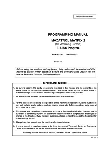
ENGINE TROUBLESHOOTINGEngine Will Not StartNOCheck For SparkSee Chapter 6under"Troubleshooting"YESWETDefective Spark PlugRestricted Air FilterImproper or Stale FuelCheck If Spark Plug Is Wet or DryCheck Fuel Supply and Fuel CapVentRestriction in Fuel System(filter, screen)Carburetion ProblemCarburetion Problems Due toFlooding, Over Priming, etc.Poor CompressionIgnition SystemBlockage in Pulse Channel toCarburetorPlugged Muffler or Exhaust Port9
LowHaADJUSTMENTSSTARTrdStartinFugel DrippinFlogFodromsEngCIDinLEe W arbur(LoehewSn N torWipeeotll NRud)otnnIdlingRicehIdleId lesWithNeErred laticeCIdllo seed"L"NeedleLoNeadsed sUpFreWhACquien tle ICELEdliAdnRjusgWiATtmll NIOen AHICclceloGHsingeraSPtioThEEnrotWiDtlell
3. Cover the spark plug hole with a shop towel and crank the engine over, slowly, several times. 4. Replace the spark plug and tighten (see step # 5 under Tune-Up Procedure for proper spar