Transcription
Politecnico di TorinoPorto Institutional Repository[Article] Plastic localization phenomena in a Mn-alloyed austenitic steelOriginal Citation:Scavino G., D’Aiuto F., Matteis P., Russo Spena P., Firrao D. (2010). Plastic localization phenomenain a Mn-alloyed austenitic steel. In: METALLURGICAL AND MATERIALS TRANSACTIONS. A,PHYSICAL METALLURGY AND MATERIALS SCIENCE, vol. 41, pp. 1493-1501. - ISSN 10735623Availability:This version is available at : http://porto.polito.it/2317506/ since: April 2010Published version:DOI:10.1007/s11661-010-0191-9Terms of use:This article is made available under terms and conditions applicable to Open Access Policy Article("Public - All rights reserved") , as described at http://porto.polito.it/terms and conditions.htmlPorto, the institutional repository of the Politecnico di Torino, is provided by the University Libraryand the IT-Services. The aim is to enable open access to all the world. Please share with us howthis access benefits you. Your story matters.(Article begins on next page)
Plastic Localization Phenomena in a Mn-Alloyed Austenitic SteelG. Scavino1, F. D’Aiuto3, P. Matteis1, P. Russo Spena2 and D. Firrao1This is the author post-print version of an article published onMetallurgical and Materials Transactions A, Vol. 41, pp. 1493-1501,2010 (ISSN 1073-5623).The final publication is available at link.springer.com.This version does not contain journal formatting and may contain minorchanges with respect to the published edition.The present version is accessible on PORTO, the Open AccessRepository of the Politecnico of Torino, in compliance with thepublisher’s copyright policy.Copyright owner: Springer.(1) Department of Materials Science and Chemical Engineering (DISMIC), Politecnico di Torino (Torino TechnicalUniversity), Torino, It, 10129, Italy(2) Department of Production Systems and Business Economics (DISPEA), Politecnico di Torino (Torino TechnicalUniversity), Torino, It, 10129, Italy(3) Engineering & Design, Fiat Group Automobiles, Torino, It, 10135, ItalyD. FirraoFull ProfessorEmail: donato.firrao@polito.itAbstractA 0.5 wt pct C, 22 wt pct Mn austenitic steel, recently proposed for fabricating automotive body structures by cold sheetforming, exhibits plastic localizations (PLs) during uniaxial tensile tests, yet showing a favorable overall strength andductility. No localization happens during biaxial Erichsen cupping tests. Full-thickness tensile and Erichsen specimens,cut from as-produced steel sheets, were polished and tested at different strain rates. During the tensile tests, the PLphenomena consist first of macroscopic deformation bands traveling along the tensile axis, and then of a series ofsuccessive stationary deformation bands, each adjacent to the preceding ones; both types of bands involve the fullspecimen width and yield a macroscopically observable surface relief. No comparable surface relief was observed
during the standard Erichsen tests. Because the stress state is known to influence PL phenomena, reduced-widthErichsen tests were performed on polished sheet specimens, in order to explore the transition from biaxial to uniaxialloading; surface relief lines were observed on a 20-mm-wide specimen, but not on wider ones.Manuscript submitted January 22, 2009.1 IntroductionHIGH manganese austenitic alloys have a remarkable combination of strength and ductility, which makes theminteresting for the automotive industry. Steels used for automotive components, such as anti-intrusion bars andstructural parts, must display high tensile strength, biaxial ductility, and energy absorption capability for improved fuelsaving, crash-test performance, and capability to deep draw complex shapes. High-manganese steels exhibit a bettercombination of high strength and ductility than most present automotive steels, such as ferritic deep-drawing steels,high-strength low-alloy steels, or multiphase steels. This is due to the mode of deformation: in addition to thedislocation slip mechanism, high-manganese steels also deform by mechanical twinning (this is often called thetwinning-induced plasticity, or TWIP, effect), and the twin boundaries behave as obstacles to dislocation movement,similarly to grain boundaries or dislocation forests.Works have already been performed in alloy development, microstructure analysis, and mechanical properties of TWIPsteels;[1–9] moreover, some recent articles reported the occurrence of plastic instabilities during uniaxial deformationtests;[10–12] the latter phenomenon was attributed either to plain dynamic strain aging, due to interactions betweenmobile dislocations and point-defect complexes including interstitial C atoms,[10] or to not yet clarified, more complexatomic interactions, also involving twinning phenomena.[11]In the present article, the mechanism of plastic deformation of a batch produced 1.5-mm-thick TWIP sheet steel (with0.5 pct C) has been studied in-depth, with the purpose of describing and explaining the occurrence of plasticinstabilities, with both uniaxial and biaxial deformation experiments. To investigate plastic instabilities, several tensiletests were performed at low to medium crosshead speeds, thus varying the applied strain rates, accordingly. Moreover,standard and reduced-width Erichsen tests were done to investigate the influence of biaxial stresses on plasticinstabilities.
2 Experimental ProceduresThe chemical composition of the TWIP steel is reported in Table I. Manganese is the main alloy element and stabilizesthe austenitic matrix at room temperature; carbon is employed to increment the yield and tensile strength by interstitialsolute hardening.The microstructural characterization was carried out both by scanning electron microscopy (SEM, with the electronchanneling contrast technique), after electrochemical etch, and by optical microscopy, after nital or picral etch. Theaustenitic average grain size was determined by using the circular intercept method[13] on optical microscopy images,after picral etch. Macro- and microhardness Vickers tests were performed on virgin material to evaluate the occurrenceof mechanical inhomogeneities.Full-thickness tensile flat specimens (80-mm gage length, 20-mm width) and Erichsen both standard (100 100 mm)and reduced width (10 100, 20 100, and 30 100 mm) test pieces were cut from as-produced TWIP steel sheets.The tensile specimens were oriented in the rolling direction. All the tests were performed at room temperature.The Erichsen cupping tests (on both standard and reduced width specimens) were performed by using the proprietary“OKS 200,” Mo2S-based, lubricant paste, which was evenly applied on the specimen area in contact with the punch.Tensile tests were carried out under displacement control, by a servohydraulic testing system controlled at four differentcrosshead speeds, namely, 0.05, 0.5, 5, and 39 mm/s. During each test, different strain rates, in the 0.0003 to 0.0005 s 1,0.003 to 0.005 s 1, 0.03 to 0.05 s 1, and 0.2 to 0.4 s 1 ranges, respectively, were achieved.The specimens were mirror polished before the mechanical tests in order to observe the transient macroscopic specimensurface relief due to plastic instabilities (this was recorded by a video camera during the tensile tests) and to examine,thereafter, both the residual surface relief and the deformed microstructure without further preparation, to avoidartifacts.In order to facilitate the observation of the transient surface relief, most tensile tests were performed withoutextensometers; thus, in several instances, the engineering stress-strain curves were derived from the recorded crossheaddisplacement, instead of from the extensometer signal, by using the following procedure. First, the crossheaddisplacement was corrected by subtracting the displacement due to the estimated elastic compliance of the load frameand of the specimen end grips (even if this correction was relevant only before the specimen yielding). Then, theengineering stress s was calculated as usual and the engineering strain e was calculated as the corrected crossheaddisplacement divided by an effective specimen length (equal to 108 mm), which was found by a trial and errorprocedure, by comparing the engineering stress-strain curves of the same test obtained either from the crossheaddisplacement or from the extensometer displacement. This effective length was employed because not only the 80-mm
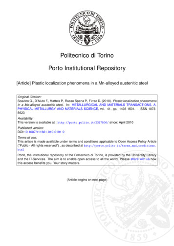
gage length, but also the specimen end regions (having a large fillet radius) were significantly deformed during thetests. Finally, the true stress σ and strain ε were calculated from the engineering ones with the usual formulas, as if thespecimen deformation had been homogeneous (i.e., by neglecting the localized deformation phenomena); hence, thetrue stress and true strain values are spatial averages.Lateral surface X-ray diffraction analyses were performed before and after the tensile tests, to reveal second phases(occurring in detectable amount) as well as the possible occurrence of deformation-induced martensitic transformations.SEM analysis was also performed on the fracture surfaces of tensile samples.3 ResultsThe optical microscope and SEM observations and the X-ray diffraction analyses show that the as-received TWIP steelconsists of homogeneous and isotropic austenite grains, with an average size of about 3 μm (Figure 1); thus, the materialwas fully recrystallized after (or during) the final sheet forming operations. However, the metallographic etch (nital andpicral) of sheet cross sections allows detection of a banding contrast, superimposed to the aforementioned homogeneousand isotropic grain-boundary network (Figure 1(b)); these bands are attributed to small compositional segregationsarising from the solidification process and elongated in the rolling direction.The X-ray analysis did not detect any phases other than austenite; it allows us to conclude that the formation of the M 3Ccarbides foreseen by the Fe-C-Mn ternary phase diagram at temperatures below 600 C[14] was probably suppressed bythe thermomechanical process; however, the presence of sub-micron-sized alloy carbides (e.g., VC) cannot becompletely ruled out. The very fine grain size was probably due to the contribution of both the thermomechanicalprocess and the grain-refining effect of V.All the as-received samples have a similar Vickers hardness, about 290 HV100. No significant microhardness differencewas detected on the sheet cross section; thus, it is concluded that the production process does not yield sensiblemechanical inhomogeneities in the sheet thickness.The engineering and true stress-strain curves of the examined steel are plotted in Figure 2, and the corresponding tensileproperties are listed in Table II, as a function of the crosshead speed; the average (estimated) strain rate of each test isalso reported in the same table. It is confirmed that the TWIP steel exhibits a remarkable combination of strength andductility, with a large and almost constant strain hardening slope, as previously noted in high-Mn steels.[1,2]The yield strength of the TWIP steel does not vary significantly with the crosshead speed in the examined range, withvalues around 550 MPa. As a contrast, as the crosshead speed is increased from 0.05 to 39 mm/s, the strain hardening
slope and the pointwise flow stress (Figure 2) slightly decrease. Finally, rupture elongation displays the largest values atintermediate crosshead speeds.Stress-strain curves exhibit smooth or serrated regions as a function of strain and of crosshead speed, thus revealingdifferent plastic behaviors. The serrations are attributed to plastic localization (PL) effects, which are also evidencedduring the test by macroscopic specimen surface relief lines, either transient or permanent. No such effects weredetected in the tensile test carried out at 39 mm/s crosshead speed, showing a smooth stress-strain curve.On the contrary, at crosshead speeds equal or lower than 5 mm/s, and starting from a critical engineering strain e c (ortrue strain ε c ), successive macroscopic bands appear on the surface on the tensile specimen, forming angles of about55 deg with the tensile axis and involving the entire section of the specimen; these bands are defined here as type Ibands. These bands spread through the specimen length, a new one being nucleated as the previous reaches onespecimen grip end, continuously repeating the same mechanism. Contemporaneously, the stress-strain curve detected bythe displacement gage shows a series of steps, each corresponding to the transit of a band through the gage length(Figure 3), and the stress-strain curve detected by the crosshead displacement shows isolated stress peaks (Figure 2),each immediately preceding the nucleation of a new band. Afterward, and up to rupture, a series of stationarydeformation bands appears, giving off distinctive sharp noises, forming angles of about 55 deg with the tensile axis,most being immediately adjacent to the preceding ones; these are defined here as type II bands.As the crosshead speed increases from 0.05 to 5 mm/s, the critical point e c (or ε c ) at which type I bands start increasesfrom 0.17 to 0.44 engineering strain (or 0.16 to 0.37 true strain), and these bands travel faster and faster throughout thetensile samples.To enhance the visibility of the effects of the propagation of the type I bands, an enlarged portion of the true stress–truestrain curve of the 0.05 mm/s crosshead speed test, recorded by the use of a 25-mm gage extensometer, is shown inFigure 3(a). Successive short plastic flows at quasi-constant stress are evident: they take place when a type I bandcrosses the gage measurement zone (Figure 3(b)) and are followed by a steep stress increase, until a successive type Iband travels through the gage zone, repeating the same pattern. In Figure 3(a), a series of light lines having a slopeequal to the steel elastic modulus are superimposed to these stress steps, showing that the slope of the true tensile curverecorded by the strain gage can be at times equal to the elastic modulus, although it is generally lower than that.Enlarged portions of the stress-strain curves, during the occurrence of type II bands, are displayed in Figure 4(a). In thiscase, no strain gage was mounted and the sample overall strain was measured by means of the crosshead displacementtransducer. When a type II band appears, the tensile stress suddenly drops at almost constant strain (in order to maintainthe imposed crosshead speed). The type II bands are evident on tensile specimens as permanent crossed macroscopic
surface relief lines (Figure 4(b)). Careful examination of the stress-strain curves (Figure 2) reveals that the amplitude ofthe stress drops, associated with type II bands, overall increases with the crosshead speed.As a function of crosshead speed, the tensile specimen failed in different ways (Figure 5): at the lower tested crossheadspeed, the fracture was almost orthogonal to the tensile axis, whereas at the highest crosshead speeds, it generallyoccurred at an angle of approximately 45 deg with respect to the tensile axis, sometimes with a small central orthogonalfracture zone and with oblique lateral regions (with either equal or opposite slope, due to the equal occurrenceprobability of α and β macroscopic slip line theory characteristic lines, as described in Reference 10).SEM investigations of fractured tensile samples show surface steps (on the previously polished lateral surfaces,Figure 6(a)) with spacing of tenths of micrometers, which are limited by the (deformed) grain boundaries; these areprobably traces of either mechanical twins or slip planes.The tensile specimen fracture surfaces (Figure 6(b)) are completely ductile (neither cleavage nor intergranular rupture ispresent) with very small dimples, consistent with the fine microstructure of the as-received steel. The fracture surfacemorphology does not change within the examined tensile test’s crosshead speed range.The X-ray diffraction measurements performed on the as-received sheet and on the deformed steel after a tensile test(crosshead speed 0.1 mm/s) are compared in Figure 7. No peaks ascribable to bct-martensite or hcp-martensite areobserved. On the other hand, both the intensity and the width of the peaks are changed by the test due to thereorientation of the austenite crystal structure.The standard Erichsen tests were performed with different average punch speeds v p . When the punch displacement isequal to the punch radius r p (10 mm), the shape of the specimen’s deformed region can be approximated by ahemisphere and the (true) linear strain in the sheet plane can be defined as 0.5·ln(A 1/A0) 0.35, where A 1 2π·r p 2 isthe area of the aforementioned hemisphere, and A 0 π·r p 2 is the area of the punch projection on the undeformedsheet. Therefore, the (true) strain rate and the (true) strain at rupture occurring during the reported standard Erichsen testcan be roughly estimated as 0.35/(r p /v p ) and 0.35·(E i/r p ), where E i is the Erichsen index. The standard Erichsentest results are reported in Table III (results of the test performed with the maximum punch speed are affected by alarger uncertainty), with the strain rates and strains at fracture estimated by this method. No macroscopic surface reliefwas detected during these tests; moreover, no serrations were detected in the acquired force-displacement curves.The reduced-width Erichsen tests were performed at the lowest available punch speed. All the specimens were brokenclose to the border of the clamping dies. No transient macroscopic surface relief was detected visually during thesetests. The successive analysis of the fractured specimens, performed at low magnification with a light microscope,revealed a series of parallel surface relief lines in the 20-mm-wide specimen (Figure 8), although in one region only(close to the final rupture) out of four possible symmetrical ones. These surface relief lines form a 45 deg angle with
the longer specimen side, which is also the main apparent local deformation direction. No analogous features weredetected in the other specimens; however, the 10-mm-width specimen exhibited, on a large part of its deformed area,surface marks due to slide through the clamping dies, which could easily have hindered any possible surface relief dueto PLs.4 DiscussionIrregular plastic flow was shown to occur while tensile testing TWIP steel sheets in a certain range of strain and strainrates at room temperature. Chakrabarti and Spretnak[15] showed that PLs (other than necking) as a general rule canoccur when the following constitutive equation is satisfied:In the adiabatic plastic deformation case (in which the temperature rise due to localized plastic deformation inducesthermal softening, which in turn decrease the local flow stress and thus allows further localized deformation), thiscondition is achieved by a relatively large negative thermal contribution (dσ/dT)δT upon raising the temperature byadiabatic heating, the other contributions being positive but lower than the thermal one. Due to heat flowconsiderations, adiabatic instabilities normally occur at very large (ballistic) strain rates, much larger than thoseexamined here.[15] When adiabatic instabilities were previously observed in AISI 4340 steel at moderate strain rates,they were allowed by the very low strain hardening slope of the quenched and tempered steel,[16,17] whereas in thepresent steel, the strain hardening is comparatively higher. Moreover, due to the same heat flow considerations,adiabatic instabilities should be favored by increasing strain rates,[15] whereas in the present case, the opposite holds.Therefore, the possible thermal contribution to the present PLs should be limited.Plastic localization behaviors similar to the present one were previously observed in other alloys and referred to as“serrated flow” or “repetitive yielding” or “jerky flow,” and have been often attributed to the Portevin–Le Chatelier(PLC) effect.[18] In these cases, the unstable plastic flow is due to a decrease of the flow stress with increasing appliedstrain rate,[18] i.e., to a large negative dσ/dε term in the previous constitutive equation, whereas the stress-strain curvestill displays positive strain hardening;[18] this phenomenon is often called negative strain-rate sensitivity or strain-ratesoftening. In these PLC cases, the thermal softening contribution may be negligible; for example, previous tests on AlMg alloys showed temperature increases associated with room-temperature PLC effects of the order of 5 C or less.[19]It has been clarified[20,21] that repeated dislocation pinning by interstitial solute elements is a necessary condition toproduce a negative strain rate sensitivity and, hence, macroscopically visible PLC serrations in tensile stress-strain
curves. During the waiting time spent at obstacles, glide dislocations are subjected to an additional pinning by soluteatoms diffusing toward the dislocations, so that the obstacle strength increases as the waiting times increase due to alow macroscopic strain rate. The negative strain rate sensitivity arises because larger macroscopic strain ratescorrespond to smaller dislocation waiting times and hence to lower solute-pinning effects.[18]The plastic instabilities appear as surface bands propagating throughout the specimen, which may be stationary (type Cbands) or may travel along the tensile axis, either through the whole specimen length (type A bands) or only throughpart of it (type B bands), as defined in Reference 18. Moreover, C bands can occur in series, each being immediatelyahead of the previous one in the same tensile axis direction, so that the overall phenomenon can still be interpreted as aPL front moving along the specimen axis, even if by discrete steps, rather than continuously advancing throughout thespecimen.[22]The overall negative strain rate sensitivity of the TWIP steel, and the nature of the type I and type II PL bands duringthe tensile tests performed at 0.04 s 1 or at lower strain rates (5 mm/s or lower crosshead speeds) in the same steel, asdescribed previously, are both consistent with the occurrence of a PLC effect in the TWIP steel; in this regard, the type Iand type II PL bands described previously are recognized as type A and type C PLC bands. Type B deformation bandswere not unequivocally detected by macroscopic transient surface relief observations, but were probably present duringthe transition between type A and C bands in the above described TWIP steel tensile specimens; such a hypothesis isalso supported by the comparison of the s-eserration shape in the transition from A to C bands with previous results.[22]Further tensile tests will be necessary in order to define the exact threshold strain rate above which the PLC effectdisappears; from the preceding results, it is possible to conclude that in the present steel such a threshold is comprisedbetween 0.04 and 0.3 s 1 uniaxial strain rate (5 and 39 mm/s crosshead speed in the present tests series).The previously described dislocation pinning by interstitial solute elements, occurring during the test, which is alsonamed dynamic strain aging, is hypothesized to be the primary mechanism inducing the PLC effect in this alloy;however, the exact nature of the interaction between mobile dislocations and solute atoms is still controversial and othermechanisms causing PLC effects are proposed in the literature.[10,11,23,24]The present results and interpretation regarding the occurrence of type A PLC bands during room-temperature tensiletests are in overall agreement with some recent observations concerning C-alloyed TWIP steels;[10–12] on the contrary,the occurrence of type C PLC bands was not reported in the same articles.Since the strain localization associated with the PLC effect replicates (as opposed to the Lüders bands, which occur onlyat first yield), it cannot be suppressed by predeformation (skin pass): surface markings and waviness of aestheticconcern may be expected during sheet forming operations due to inhomogeneous plastic deformation.
The full-width Erichsen test results confirm the negative strain rate sensitivity of the present steel, since the force atrupture (which is positively correlated with the maximum flow stress value) significantly decreases with increasingstrain rate. However, no PLs were observed in the slowest full-width Erichsen tests (i.e., those performed with thesmaller punch speeds, Table III) even if they satisfied, in each strain direction, the uniaxial strain and strain rateconditions that induced PLs in tensile tests (Table II); only in the faster Erichsen tests could the absence of PLs beascribed to the strain rate being too high, or the strain to fracture being too low. Therefore, it should be concluded thatthe biaxial stress state has an impeding effect upon the occurrence of PL phenomena. This conclusion is consistent withthe results of the reduced-width Erichsen tests, in which the stress state becomes less and less biaxial with decreasingtestpiece width. In fact, no surface relief lines were detected in the 30-mm-width test, and only very shallow (i.e., muchless evident than those observed in the tensile tests) ones were observed in the 20-mm-width tests. Therefore, on thebasis of these results, the PLC effect is not expected to significantly deteriorate the surface quality of sheet-formedcomponents, since these are often subjected to significantly biaxial stress states.It should be noted that, even at the higher examined strain rate, which promotes the absence of plastic instabilities andof aesthetically detrimental marks, the strength and ductility combination of the TWIP steel is still remarkable in respectto other steel grades employed in deep drawing applications.Finally, the absence of martensite after the room-temperature tensile tests, assessed by the XRD analyses, can be relatedto the examined steel stacking fault energy (SFE). Remy and Pineau[25] reported deformation-induced martensitictransformations in a 20 pct Mn, 4 pct Cr, 0.5 pct C austenitic steel at temperatures equal or lower than 32 C, with SFEhaving been determined as equal to 11 mJ/m2; thus, it can be hypothesized that the present steel has a somewhat higherSFE than that, which is consistent with previous observations that the SFE of high-Mn austenitic steels increases withboth the Mn and C content and decreases with the Cr content.[5] This is also consistent with the finding thatdeformation-induced martensitic transformations occur in a 25 pct Mn austenitic steel with less than 0.05 pct C only attemperatures lower than –70 C,[2] since in this latter case the much lower C content further decreases the SFE value.5 Summary And ConclusionsThe overall plastic behavior of an austenitic high manganese carbon steel has been examined by using different strainand stress rates on both uniaxial tensile specimens and biaxial Erichsen cupping testpieces. Erichsen tests wereperformed either on standard or on reduced-width specimens. The following remarks can be made.1.The TWIP steel exhibits PLs during uniaxial tensile tests for strain rates lower than 0.3 s 1. These plasticinstabilities are due to a PLC effect, and in particular they are probably caused by the observed negative strainrate sensitivity (decreasing the flow stress with increasing strain rate). The plastic instabilities appear as easilyvisible successive surface bands; the first bands travel throughout the specimen length (type A bands), whereas
the stationary bands (type C bands) appear later and up to the final fracture. As the strain rate of the tensile testincreases from 0.0004 to 0.04 s 1, the critical deformation at which type A bands appear increases from 0.17 to0.44 engineering strain (or 0.16 to 0.37 true strain), and these bands travel faster throughout the tensilesamples.2.The standard Erichsen test results are consistent with a negative strain rate sensitivity of the TWIP steel, sincethe force at rupture, and hence the maximum flow stress value, significantly decreases with increasing strainrate. However, no macroscopic localization happens during these tests; thus, the biaxial stress state preventsthe PL phenomena. This is consistent with the observation of few surface relief lines at low magnification on a20-mm-width Erichsen specimen, since its stress state is less biaxial.3.On the basis of X-ray diffraction analyses, performed before and after the tensile tests, no deformation-inducedmartensitic transformations occur during the deformation of the austenitic microstructure. The absence ofmartensite is consistent with an estimated rather high SFE.AcknowledgmentsArcelorMittal steelwork for steel procurement. P. Iulita, Fiat Auto Engineering & Design, for the SEM microstructuralanalysis. C. Pozzi, Politecnico di Torino, for the X-ray analyses. G.M.M. Mortarino, Politecnico di Torino, forcollaboration in tensile testing and for useful discussion.
References1. O. Grässel and G. Frommeyer: Mater. Sci. Technol., 1998, vol. 14, pp. 1213–16.2. O. Grässel, L. Kruger, G. Frommeyer, and L.W. Meyer: Int. J. Plasticity, 2000, vol. 16, pp. 1391–1409.MATHCrossRef3. P. Yang, Q. Xie, L. Meng, H. Ding, and Z. Tang: Scripta Mater., 2006, vol. 55, pp. 629–31.CrossRef4. S. Vercammen, B. Blanpain, B.C.D. Cooman, and P. Wollants: Acta Metall., 2004, vol. 52, pp. 2005–12.5. O. Bouaziz and N. Guelton: Mater. Sci. Eng. A, 2001, vols. 319–321, pp. 246–49.6. S. Allain, J.P. Chateau, and O. Bouaziz: Mater. Sci. Eng. A, 2004, vols. 387–389, pp. 143–47.7. S. Allain, J.P. Chateau, and O. Bouaziz: Steel Res., 2002, vol. 73, pp. 299–302.8. D. Cornette, P. Cugy, A. Hildenbrand, Bouzekri, and G. Lovato: Rev. Metall., 2005, Dec., pp. 905–18.9. G. Frommeyer, U. Brux, and P. Neumann: ISIJ Int., 2003, vol. 43, pp. 438–46.CrossRef10. J.K. Kim, L. Chen, H.S.
channeling contrast technique), after electrochemical etch, and by optical microscopy, after nital or picral etch. The austenitic average grain size was determined by using the circular intercept method[13] on optic