Transcription
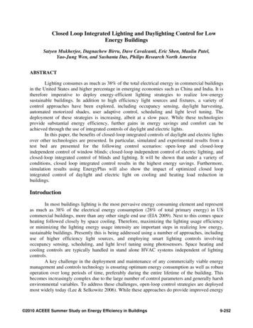
Closed Loop Integrated Lighting and Daylighting Control for LowEnergy BuildingsSatyen Mukherjee, Dagnachew Birru, Dave Cavalcanti, Eric Shen, Maulin Patel,Yao-Jung Wen, and Sushanta Das, Philips Research North AmericaABSTRACTLighting consumes as much as 38% of the total electrical energy in commercial buildingsin the United States and higher percentage in emerging economies such as China and India. It istherefore imperative to deploy energy-efficient lighting strategies to realize low-energysustainable buildings. In addition to high efficiency light sources and fixtures, a variety ofcontrol approaches have been explored, including occupancy sensing, daylight harvesting,automated motorized shades, user adaptive control, scheduling and light level tuning. Thedeployment of these strategies is increasing, albeit at a slow pace. While these technologiesprovide substantial energy efficiency, further gains in energy savings and comfort can beachieved through the use of integrated controls of daylight and electric lights.In this paper, the benefits of closed-loop integrated controls of daylight and electric lightsover other technologies are presented. In particular, simulated and experimental results from atest bed are presented for the following control scenarios: open-loop and closed-loopindependent control of window blinds; closed-loop independent control of electric lighting, andclosed-loop integrated control of blinds and lighting. It will be shown that under a variety ofconditions, closed loop integrated control results in the highest energy savings. Furthermore,simulation results using EnergyPlus will also show the impact of optimized closed loopintegrated control of daylight and electric light on cooling and heating load reduction inbuildings.IntroductionIn most buildings lighting is the most pervasive energy consuming element and representas much as 38% of the electrical energy consumption (28% of total primary energy) in UScommercial buildings, more than any other single end use (EIA 2009). Next to this comes spaceheating followed closely by space cooling. Therefore, maximizing the lighting usage efficiencyor minimizing the lighting energy usage intensity are important steps in realizing low energy,sustainable buildings. Presently this is being addressed using a number of approaches, includinguse of higher efficiency light sources, and employing smart lighting controls involvingoccupancy sensing, scheduling, and light level tuning using photosensors. Space heating andcooling controls are typically handled in stand alone HVAC systems independent of lightingcontrols.A key challenge in the deployment and maintenance of any commercially viable energymanagement and controls technology is ensuring optimum energy consumption as well as robustoperation over long periods of time, preferably during the entire lifetime of the building. Thisbecomes increasingly complex due to the large number of control parameters and generally harshenvironmental variables. To address these challenges, open-loop control strategies are deployedmost widely today (Lee & Selkowitz 2006). While these approaches do provide improved energy 2010 ACEEE Summer Study on Energy Efficiency in Buildings9-252
efficiency, they may not always provide the optimum performance and require calibration ortuning periodically to ensure intended performance. To address these limitations, closed-loopcontrol strategies have been explored (Bierman 2007; Jennings 2000; Rubinstein, Ward &Verderber 1989) with varying degrees of success depending upon the algorithms employed andthe loop gain settings.In this paper, a study of closed-loop integrated controls of daylight and electric lightshave been carried out to evaluate the benefits and potential challenges in actual implementation.In the integrated control mode, electric lighting and the blinds were controlled in an integratedmanner by sharing the light level measured at a reference point between the two elements andminimizing the lamp energy consumption while maintaining the required light level on the worksurface. The integrated controls strategy is compared against two independent controlapproaches, in which the electric lighting and the blinds were independently controlled toprovide user desired light level on the work surfaces while external conditions varied. Analyticalsimulation of the control strategies have been carried out to quantify the energy savings possibleunder various conditions. Furthermore, an experimental test bed comprising of motorized blindson windows, dimmable fluorescent lamps in the ceilings, photo and occupancy sensors has beenutilized to quantify the energy savings under real conditions and demonstrate some of theoperational limitations of independent control strategies.Finally, EnergyPlus (EnergyPlus) simulations have been carried out, for typical midsizedoffice buildings, to quantify the impact of optimized closed loop integrated control of daylightand electric light on cooling and heating loads. EnergyPlus, developed by the U.S. DOE, is abuilding energy analysis and thermal load simulation program which provides simultaneousloads and systems simulation for accurate temperature and comfort prediction.Control StrategiesBuilding control strategies can be broadly divided into open-loop and closed-loopcontrols. Open-loop controls are those that adjust the output based on external input only. Thereis no feedback mechanism to regulate the output. Closed-loop strategies, on the other hand,employ feedback along with external input to regulate the output and meet a certain operating setpoint, or a range of set points. In this paper, we have explored both open-loop and closed-loopcontrol of window blinds, closed loop control of electric lights, and integrated controls of thesebuilding subsystems. In the following subsections, a detailed description of the control strategiesevaluated in this paper is provided.Lighting Control SystemFigure 1 Closed-loop electric lighting control system 2010 ACEEE Summer Study on Energy Efficiency in Buildings9-253
Closed-loop electric lighting control systems are currently the most advanced daylightharvesting systems offered on the market. Figure 1 shows a simplified diagram of a closed-looplighting control system. An interior photosensor measures the combination of daylight andelectric light. The sensor output is compared with a reference set point. The electric lights areadjusted accordingly to maintain the task illuminance within a predefined range.In this study, we assumed a full-range dimmable lighting system and implemented anintegral controller where the sensors measure the task plane illuminance. The control law isshown in equation (1), where u(k) is the light dimming signal, e(k) is the difference betweensensed illuminance and the set point at the kth time step, and Kp is the constant gain of thecontroller.(1)Venetian Blind Control SystemsWhile the majority of venetian blinds are still manually operated, automated blindsystems have been implemented in cutting-edge practices for efficient daylight harvesting andvisual comfort control. In this study, we have considered both open-loop and closed-loop blindcontrols as described below.Open-loop motorized Venetian blind control systems. Open-loop configuration, as illustratedin Figure 2, deploys/retracts the blinds or opens/closes the blind slats to regulate the admission ofthe daylight. This configuration utilizes external information (e.g. angle of incidence of sun light)and/or sensor measurements to make control decisions. One existing practice makes use of solarposition, which is pre-calculated or measured by sun tracker, to block direct sun beam andprevent daylight glare (Skelly & Wilkinson 2001; Vine et al. 1998). Other control setups in theliterature utilize sensor measurements of exterior façade illuminance (Reinhart & Voss 2003;Kim et al. 2009) or incoming direct solar radiation (Reinhart 2004) to dynamically adjust theblinds for a comfortable visual and thermal interior environment. In addition, seasonalinformation may also be incorporated to decide whether to admit or reject solar radiation byopening or closing the blinds thereby minimizing space conditioning energy usage for betteroverall energy efficiency (Shen & Hong 2009). In any case, open-loop setups require carefulcalibration and commissioning to match sensor measurements with control actions.Figure 2 Open-Loop Motorized Venetian Blind Control SystemClosed-loop motorized Venetian blind control systems. A closed-loop blind system bases itscontrol decisions on the interior lighting condition measured by a photosensor as shown inFigure 3. Compared to an open-loop blind system, the sensor in a closed-loop configuration sees 2010 ACEEE Summer Study on Energy Efficiency in Buildings9-254
the direct results from blind control actions, and hence is more robust to uncertainties anddisturbances related to commissioning and space characteristics.Figure 3 Closed-Loop Motorized Venetian Blind Control SystemIn our experimental setup, we implemented a fixed-step control law to dynamically adjustthe blind slat angle while assuming that the blind is always deployed. The blinds are opened(closed) incrementally with a fixed step until the set point of the interior task plane illuminance ismet. In addition to the fixed-step control, other control strategies may also be applied, such asintegral control similar to equation (1). As will be discussed in the following sections, thisstrategy, if implemented independent of the electric lights, will result in severe performancepenalties in terms of user comfort and energy savings.System Integration StrategiesElectric lighting control and daylight shading control are both essential for regulatinginterior lighting condition. It is critical for both systems to complement each other and create acomfortable visual environment with maximum energy efficiency. A straightforward approach isto operate them independently as illustrated in Figure 4, referred hereafter as “independentcontrol”. These strategies have several critical drawbacks and will be discussed later on.Figure 4 (a) Independent control of closedloop lighting system and open-loop blindsystemFigure 4 (b) Independent control of closedloop lighting system and closed-loop blindsystem 2010 ACEEE Summer Study on Energy Efficiency in Buildings9-255
A truly integrated closed-loop system is illustrated in Figure 5. The goal of this integratedcontrol is to regulate task illuminance at a prescribed set point while maximizing daylightutilization, hence minimizing electric lighting load. In this strategy both systems share theinformation from a single photosensor that measures interior task illuminance. The operation ofsuch a system is as follows.When more light is required to meet the set point and blinds slats are partially open thenthe controller will first open the blind slats incrementally to admit more daylight and if the setpoint cannot be met even after the blinds are fully open then use electric lights to compensate forinsufficient daylight. Similarly, when task illuminance exceeds the set point, the electric lightswill be dimmed first, and if the set point is not reached even after the lights are turned off thenthe blind slats are closed incrementally to reduce daylight admission until the task illuminancemeets the target. The electric lights control follows Eq. 1 while that for the blinds follows theclosed-loop blinds control described above.Figure 5 Integrated Lighting and Daylight Control SystemIn addition to the sequential approach described above, it is possible to develop moresophisticated integration strategies with broader considerations for better performances. Forinstance, in addition to daylight utilization and lighting electricity energy minimization, theimpact of fenestration on solar heat gain may be incorporated to reduce HVAC system load andachieve higher overall energy efficiency.Another important aspect of window transmission controls is to avoid discomfort glarefrom daylight. In our study, we have explored the use of an external sensor to measure thevertical illuminance incident on the window. We adjust the position of the blinds to avoid highintensity light entering the work plane with an aim to reduce discomfort glare from directsunlight. While our strategy to block high intensity light entering the work space is a simple formof glare control, further advanced strategies, for example measuring vertical illuminance at eyeor luminance contrast ratios at the workplane, could also be combined with this strategy for amore effective and optimum glare control. A study of large glare sources by Osterhaus(Osterhaus 1998) in 1998 showed a correlation between a subjective rating of glare (SGR) andvertical illuminance or overall brightness in the field of view of the occupant. A more recentpaper by Osterhaus (Osterhaus 2008) illustrates that the ratio of (also, difference between) theaverage to median luminance in the field of view correlates strongly to subjective glare ratings.In 2006, Wienold and Christoffersen developed a new glare formula (DGP) (Wienold & 2010 ACEEE Summer Study on Energy Efficiency in Buildings9-256
Christoffersen 2006) to incorporate the effects from large glare sources. The DGP is basedprimarily on vertical illuminance at the eye combined with a term to account for individual glaresources.Control Loop PerformanceWhen two or more closed loop subsystems are operating to affect the same variable,careful design of the control strategies is required. For instance, an automated window blindscontroller and electric lights controller affect the interior illuminance. If both, independently,attempt to control the interior illuminance, then the two systems will not operate optimally, oreven result in severe performance degradation. In order to assess this, a Matlab simulation wascarried for the independent closed loop control strategies to satisfy a 500 lux work planeilluminance. The simulation results are plotted in Figure 6. As the results show, the blinds(represented as daylight in the room) remained closed while most of the lighting demand issatisfied by electric lighting. This has severe consequences on user comfort and energyconsumption. When such independent controls are deployed, each controller will be racing tomeet the set point. Usually, the faster controller, i.e., electric lights, will satisfy the lightingdemand resulting in reduced energy savings and visual comfort (less daylight and less view tothe outside). The best remedy to this is to use either open loop controls (one reason why suchstrategies are deployed today) or integrated controls proposed in this paper. In the followingsections, further results (experimental and EnergyPlus simulations) are provided evaluating theperformance of integrated controls compared to independent open loop and closed loop controls.Figure 6: Simulation Results Using Matlab Models to Evaluate the Performance of theControl LoopsIndependent Closed-loop Controls1200Available daylightTotal room lightDaylight in roomElectric light1000800light level, lux6004002000012345days678 2010 ACEEE Summer Study on Energy Efficiency in Buildings910 119-257
Experimental Testbed ResultsA testbed was developed for evaluating the different realizations of control systemintegration strategies. The system architecture is shown in Figure 7. The target space is dividedinto zones and each zone is controlled by a single zone controller (ZC). All devices within a zone(e.g. sensors, dimmable ballast and motorized blinds) communicate wirelessly with the ZCthrough the standard ZigBee protocol (ZigBee Alliance 2006).Figure 7: System ArchitectureThe ZC is responsible for centralizing the data collection, processing and implementingthe control strategies. In addition to the ZigBee interface, the ZC has another interface to abuilding-wide network (e.g. Ethernet LAN), which allows the remote communication with aDatabase and a Web Server, as depicted in Figure 7. The MySQL Database stores theconfiguration information for each zone including device types and their locations, usercredentials, user preferences and other system parameter. It is also used to log data containingreal-time monitoring information of several system performance and operational metrics. Theend users can access the system through a web interface, which provides manual and automaticcontrol options. The web system also includes facility manager and network administratorspecific web interfaces for supervisory and administrative controls. 2010 ACEEE Summer Study on Energy Efficiency in Buildings9-258
Figure 8: Desk 1 (Zone 1) configurationWireless motorizedblindsWireless dimmableballastOccupancy sensorwithWe study the performance of close-loop integrated and independent control strategiesrespecttoanorthfacinguserdeskasshownin 2010 ACEEE Summer Study on Energy Efficiency in Buildings9-259
Figure 8 in order to evaluate their daylight harvesting ability and independent and integratedcontrol strategies.The objective of both closed-loop (independent and integrated) control strategies is tomaintain illumination level at the work-plane close to the user provided set point (in lux) asmeasuredbytheDesk1LightSensorin 2010 ACEEE Summer Study on Energy Efficiency in Buildings9-260
Figure 8. In the integrated mode, the blinds and lights are jointly controlled to optimize theamount of daylight used (see Figure 5). On the other hand, in the independent mode, the samelight sensor provides current illumination level feedback to two different controllers (see Figure4), one for lights and another one for blinds, which operate independently to maintain work planeillumination level close to the set point. An exterior light sensor is used in both experiments (see 2010 ACEEE Summer Study on Energy Efficiency in Buildings9-261
Figure 8) to capture the external lighting conditions. 2010 ACEEE Summer Study on Energy Efficiency in Buildings9-262
Experiment IFigure 9: System State (Blinds, Lights and Desk Illuminance) in Exp. IBlinds Position (tilt angle)100Degrees80Independent6040Blindsfully openBlindsopen 616:35:0216:36:29TimeBallast Power16:37:5516:39:2216:40:48Integrated500 lux50IndependentIntegratedPower 2916:37:5516:39:2216:40:48TimeDesk 1 Illuminance800500 lux(Lux)600300 he first experiment presents a snapshot of the system operation for a few minutes whilea sequence of events is triggered. This experiment is useful to understand the behavior of the twocontrol strategies and it will also demonstrate some of the inherent limitations of independentcontrols. Figure 9 shows the state of blinds, light (ballast power) and the desk illuminance. Theautomatic control is started in independent mode with a 300 lux set point. Blinds are initiallyclosed (tilt angle 0o) and lights are at the maximum power (44 W), which gives approximately700 lux at the desk sensor right after the initial state. As can be seen, under the independentcontrol, lights start dimming right away and the set point is reached before the blinds can open.Next, the set point is changed to 500 lux, and both blinds and lights react to increase theilluminance at the desk. As soon as the set point is met both systems reach the steady state. Sinceboth controllers are operating independently, once the set point is met, the blinds have no 2010 ACEEE Summer Study on Energy Efficiency in Buildings9-263
incentive to open further and the lights could not dim anymore. Finally, we switch to integratedcontrol mode which caused the blinds to fully open, while lights are further dimmed to meet thesame 500 lux set point at the desk.In the second experiment, the system runs on automatic mode for one day underindependent control and another day on integrated control and the overall performance iscompared, including the blinds positions, the power consumption and the resulting work planeilluminance. Finally, we show the average power consumption over a 5 days experiment witheach control strategy. We assume the system is always occupied. The system performance duringthe 2 days tests is shown in Figure 10. As can be noted, the close-loop independent control modeis not able to maintain the blinds open as much as the integrated alternative, and thus lights werenever turned off. On the other hand, blinds were mostly fully open with integrated controlsexcept during a few early afternoon peaks in the external illuminance. Note that the integratedcontrol strategy partially closed the blinds to maintain the work-plane illumination closer to theset point when the peak in external illumination caused the work plane illumination to exceed theuser set point despite electric lights being turned off. Overall, both control strategies were able tomaintain the desk illuminance close to the 500 lux level, but the integrated approach useddaylight more efficiently, thus better visual comfort, and reduced the electric light powerconsumption by 17% compared to the independent control mode.In a 5 days test with each control strategy, the average power consumption with theindependent mode during day time was 26 W, against 21 W with the integrated control option,which represents a 19% gain in energy savings over the independent controls mode.EnergyPlus SimulationsEnergyPlus simulations were also used to explore the effects of integrated control ofdaylight and electric light on lighting and HVAC energy in a full building scale application. Themedium office benchmark model V1.0 3.0, developed by the DOE (DoE), was used as a startingpoint. The medium office benchmark model building characteristics were derived from theEnergy Information Administration Commercial Building Energy Consumption Survey 2003(EIA 2003) so that the building model is statistically representative of the installed newconstruction base in the United States. It consists of three floors and 15 occupied thermal zonescovering a total floor area of 4,982m2. The building is rectangular in shape with an aspect ratioof 1.5. Each floor consists of a central core zone covering approximately 60% of the floor areaand four perimeter zones covering approximately 40% of the floor area. The window-to-wallratio is 33% with window U-values and solar heat gain coefficients (SHGC) meeting ASHRAE90.1-2004 minimums (ANSI/ASHRAE/IESNA Standard 90.1-2004) as defined for each DOEclimate zone. Designed internal gains include interior lights at 10.76W/m2, electric plug loads at8.07W/m2, and occupancy of 195 total (3.91/100m2). Occupancy patterns and interior lightingschedules are based on ASHRAE standards and are specified hourly for the full year taking intoaccount weekdays, weekends, and holidays. 2010 ACEEE Summer Study on Energy Efficiency in Buildings9-264
Experiment IIFigure 10: Devices States and Measurements During Exp. IIBlinds position (Tilt 0012:000:00Time12:000:0012:00(Watts)Ballast :000:0012:000:0012:00TimeDesk Light 10000:0012:000:0012:000:0012:00TimeThe benchmark model was modified to implement dimming of electric lighting inresponse to available daylight in order to maintain a specified illuminance level at a referencepoint. Only the perimeter zones of the medium office building receive daylight. In eachperimeter zone, a single reference point was located along the centerline of the zone, two thirdsdeep into the perimeter space (approximately 3m from the windows), and at a workplane heightof 0.8m. The illuminance set point for the lighting control system was 500lux and 100% of thelighting in each thermal zone was controllable. An idealized approach to the control was used inorder to identify the upper bounds of energy savings. Both the light output and input power werecontrollable over the full linear range from 0 to 100%. 2010 ACEEE Summer Study on Energy Efficiency in Buildings9-265
Interior horizontal venetian blinds were added to all windows for control of daylight. Theblinds consist of highly reflective material (80% reflectivity of visible and solar) with a slatwidth of 2.5cm and a slat spacing of 1.875cm. In order to minimize convective heat transfer intothe thermal zone, the blinds were located as close as possible to the window surface.Because venetian blind slat angle control options in EnergyPlus (V3.1) are limited tofixed, scheduled, or block beam solar, the EnergyPlus model was interfaced to the BuildingControls Virtual Test Bed (BCVTB) (LBNL 2009) in order to implement a closed-loop blind slatangle controller. The BCVTB allows run-time coupling of domain specific simulation software.In this case, BCVTB release 0.3.1 was used which has interfaces to a modified version ofEnergyPlus V3.1 and Matlab. At each simulation time step illuminance data is exchanged withMatlab, which in turn calculates an increment or decrement in the blind slat angle to attempt tomaintain the illuminance set point at the desired level. The slat angle time stepincrement/decrement was limited to 2.5 degrees, with a total control range of 0 degrees (slatshorizontal) to 90 degrees (slats completely closed). The illuminance set point was 530lux with atolerance range of /- 20lux. This means for daylight illuminance values between 510lux and550lux there will be no control change in the blind slat angle. The illuminance set point for theblind controller was chosen to be higher than the illuminance set point of the electric lightingcontrol system in order to minimize the electric lighting energy. If the daylight level is less than500lux when the blinds are fully open, then the difference is made up by the electric lighting.This control strategy integrates control of daylight and electric lighting by maximizing theavailable daylight up to the set point and utilizing electric lighting if there is not enough daylightto meet the set point.Simulation cases were run for Baltimore, MD, using TMY3 weather data (Wilcox &Mariaon 2008). The simulation time step was set to one minute, which is the smallest allowabletime step in EnergyPlus. Although weather data is limited to hourly values, EnergyPlus performsinterpolation of the weather data at each time step. Thus, there are two main considerations tonote regarding these simulations. One, with simulation time steps of one minute, the truedynamics of a blind slat angle control system will not be represented. Two, with interpolatedhourly weather data, the true dynamics of real weather will not be represented. Nonetheless,given that these limitations are applicable to all the cases investigated, the comparison ofsimulation results should give a reasonable picture of yearly lighting and HVAC energy savingsresulting from integrated control of daylight and electric lighting.Table 1. Simulated Yearly Lighting and HVAC Energy Consumption for Baltimore, MDSimulation CasePerimeterLighting (GJ)LightingSavings GJ)HVACEnergyTotal(GJ)HVACSavings ntegrated Control76.9745.71016.11761.8 2010 ACEEE Summer Study on Energy Efficiency in Buildings9-266
Results are given in Table 1, comparing the yearly lighting and HVAC energyconsumption for four cases studied in this paper. The Benchmark case is the original DOEmedium office benchmark model which implements ASHRAE 90.1-2004 envelope with noblinds and no dimming of electric lighting. The Open-loop Independent case adds interiorvenetian blinds with the slat angle controlled to block direct sun (open-loop control) andimplements closed-loop control of electric lighting. The Closed-loop Independent caseimplements both closed-loop blind control and closed-loop electric lighting control with nointegration. The Integrated Control case implements integrated closed-loop control of blind slatangle and electric lighting. The perimeter lighting energy is the energy used only in theperimeter zones of the building. The heating energy is for the whole building and includes theheating system, component energy and the pump energy for the hot water reheat coils. Thecooling energy is also for the whole building and includes the cooling system and componentrelated energy as well as the fan energy (which correlates with the cooling energy).For perimeter lighting energy, Integrated Control saves 66% compared to Benchmark,8% compared to Open-loop Independent, and 23% compared to Closed-loop Independent. Infact, for interior venetian blinds, simulations show that blinds fixed at zero degrees result inperimeter lighting energy consumption of 77GJ. This is the lower limit of lighting energy, whichis achieved with Integrated Control. Open-loop Independent, which blocks direct sun, does notutilize daylight as effectively as Integrated Control. Closed-loop Independent suffers fromcompeting independent controls which results in the blinds staying closed. In the simulations theblinds were reset to the open position at the start of each day, otherwise the blinds would haveremained closed for the entire year. Generally, the addition of interior venetian blinds results indecreased cooling energy and increased heating energy, since some solar gain is blocked andreflected by the blinds. Integrated Control further decreases cooling energy by minimizingelectric lighting energy, which results in a corresponding increase in heating energy. For HVACenergy, Integrated Control saves 14% compared to Benchmark and 3% compared to Open-loopIndependent, while consuming approximately the same as Closed-loop Independent
Lighting consumes as much as 38% of the total electrical energy in commercial buildings . Kim et al. 2009) or incoming direct solar radiation (Reinhart 2004) to dynamically adjust the blinds for a comfortable visua