Transcription
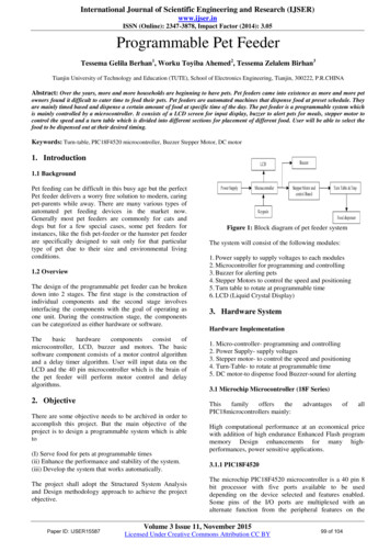
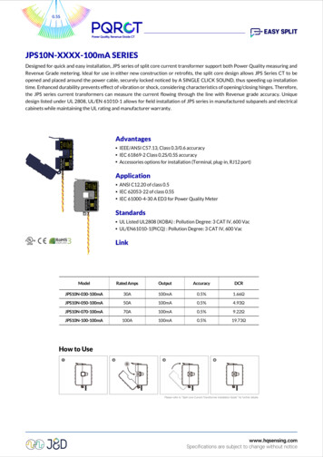
0.5SJPS10N-XXXX-100mA SERIESDesigned for quick and easy installation, JPS series of split core current transformer support both Power Quality measuring andRevenue Grade metering. Ideal for use in either new construction or retrofits, the split core design allows JPS Series CT to beopened and placed around the power cable, securely locked noticed by A SINGLE CLICK SOUND, thus speeding up installationtime. Enhanced durability prevents effect of vibration or shock, considering characteristics of opening/closing hinges. Therefore,the JPS series current transformers can measure the current flowing through the line with Revenue grade accuracy. Uniquedesign listed under UL 2808, UL/EN 61010-1 allows for field installation of JPS series in manufactured subpanels and electricalcabinets while maintaining the UL rating and manufacturer warranty.Advantages IEEE/ANSI C57.13, Class 0.3/0.6 accuracy IEC 61869-2 Class 0.2S/0.5S accuracy Accessories options for installation (Terminal, plug-in, RJ12 port)Application ANSI C12.20 of class 0.5 IEC 62053-22 of class 0.5S IEC 61000-4-30 A ED3 for Power Quality MeterStandards UL Listed UL2808 (XOBA) : Pollution Degree: 3 CAT IV, 600 Vac UL/EN61010-1(PICQ) : Pollution Degree: 3 CAT IV, 600 VacLinkModelRated A0.5%19.73ΩHow to Use❶❷❸❹ 1 1 1 1 1 1 1 1 1 1 1 1 1 1 1 1
JPS10N-XXXX-100mA SERIES1.Specifications 1.1Accuracy : Class 0.5SSystem Voltage : 720 V (0.72 kV)Overload Withstand : 1.2 times rated current continuouslyCompliant with : IEC/EN 61869-2 & IEEE/ANSI C57.13Operating Temperature Range : -40to 70Relative Humidity : 0 to 90% non-condensingTest Voltage : 3 kV for 1 minuteFrequency Range : 50/60 HzProtection Level : 3.0V0-PInsulation Category : CAT III 1000 Vac, CAT IV 600 VacOutput Lead Wires :Style : Two conductor, brown and yellow twisted pair (equivalent to about one #8 AWG 0.213" dia.), MTW, UL 1015Standard length : 8 ft (2.44m)Gauge : #18 AWGVoltage : 600VacAccuracy Ratio Error :Accuracy 0.5% conforms to IEC 61869-2 & IEEE/ANSI C57.13 meets the measuring range from 1% to 120% of In Phase Angle :50/60 Hz – 0.0 to 2.0 degrees leading from 1% to 120% of rated currentPosition Sensitivity 0.03%Shock and Air Gap Test Shock and Vibration Test Report(JPS10)100A100APhase error( )Linearity Error(%)Phase error( )Linearity Error(%)0.21- 0.150.21- 0.170.23- 0.160.22- 0.18 Core Air Gap Test Report(JPS10)100A100AAir gap : 2micronsAir gap : 2.5micronsPhase error( )Linearity Error(%)Phase error( )Linearity Error(%)0.21- 0.150.21- 0.17 1 1 1 1 1 1
JPS10N-XXXX-100mA SERIESHarmonic Graphs252015Ratio Error (%)1050246810 12 14 16 18 20 22 24 26 28 30 32 34 36 38 40 42 44 46 48 50 52 54 56 58 60 62-5-10-15-20-25HarmonicsIEC Standard MaxIEC Standard Min50Hz60Hz2520Phase displacement ( )151050246810 12 14 16 18 20 22 24 26 28 30 32 34 36 38 40 42 44 46 48 50 52 54 56 58 60 62-5-10-15-20-25HarmonicsIEC Standard Max1.250Hz60HzRegulatory 1.3IEC Standard MinCEUL Listed UL2808 (XOBA) : Pollution Degree: 3 CAT IV, 600 VacUL/EN61010-1(PICQ) : Pollution Degree: 3 CAT IV, 600 VacRoHs CompliantEnvironmental Operating Temperature : -40 C to 70 C (–40 F to 158 F)Operating Humidity : Non-condensing, 0 to 95% relative humidity(RH)Operating Altitude : Up to 3000 m (9842 feet)Pollution Degree : 3 (harsh environment)Indoor Use : Suitable for indoor useOutdoor Use : Suitable for outdoor use when mounted in a NEMA 3R or 4 (IP 66)rated enclosure, provided the ambient temperature will not exceed 55 C (131 F) 1 1 1 1 1 1
JPS10N-XXXX-100mA SERIES1.4Mechanical Width : 61mmHeight : 48mmThickness : 35mmOpening : 10mmWeight : 230gCore Nickel Core : high permeability ferriteStandard lead wire : 2.44m, ront LabelRight Side LabelLeft Side Label QR code : Model ; SerialNum ; Scan QR code for Instruction Manual Orientation : Mount the CT reffering to the right side label attached(P1- P2).2.Typical Accuracy In the following graphs, a positive phase angle error indicates that the output of the CT leads the primary current. Graphs show typical performance at 25 C, 60 Hz Performance Graphs - The standard CT meets ANSI/IEEE C57.13 class 0.6 standard & IEC 61869-2 standard class 0.52.1Schematic DiagramKKLIPP1Iout S1P2S221L 1 1 1 1 1 1
JPS10N-XXXX-100mA SERIES1803.01502.51202.0901.5601.0300.500 30 0.5 60 1.0 90 1.5 120 2.0 150 2.5 1800 1 52050100120Ratio error (%)JPS10N-030-100mAPhase Displacement ( minutes )2.2 3.0Percentage of I pr (%)1803.01502.51202.0901.5601.0300.500 30 0.5 60 1.0 90 1.5 120 2.0 150 2.5 1800 1 52050100120Ratio error (%)JPS10N-050-100mAPhase Displacement ( minutes )2.3 3.0Percentage of I pr (%)1803.01502.51202.0901.5601.0300.500 30 0.5 60 1.0 90 1.5 120 2.0 150 2.5 1800 1 52050100120Ratio error (%)JPS10N-070-100mAPhase Displacement ( minutes )2.4 3.0Percentage of I pr (%) 1 1 1 1 1 1
JPS10N-XXXX-100mA SERIES1803.01502.51202.0901.5601.0300.500 30 0.5 60 1.0 90 1.5 120 2.0 150 2.5 1800 1 52050100120Ratio error (%)JPS10N-100-100mAPhase Displacement ( minutes )2.5 3.0Percentage of I pr (%)3.SafetyThe J&D CTs are UL2808 Listed, UL/EN 61010-1, CE, RoHS compliant and certified, are also conformed up to Pollutiondegree 3, 600Vac CAT IV rated devices.Please be sure that Failure to follow these instructions can result in serious injury and/or causedamage.The transducer shall be used in electric/electronic equipment in accordance with the operatinginstructions of all related systems and component manufacturers with respect to applicablestandards and safety requirements.Follow corresponding national regulations and safe electrical work practices.This equipment must only be installed and serviced by qualified personnel. And the qualifiedpersonnel is one who has skills and knowledge related to the construction and operation of thiselectrical equipment and installations, and has received safety training to recognize and avoid thehazards involved.When operating the transducer, there may be dangerous active voltages (e.g. primary conductor)in certain parts of the module. Users should make sure to take all necessary steps to protect againstelectric shock. The transducer is a built-in device containing conductive parts that are inaccessibleafter installation. Therefore, a protective enclosure or additional insulation barrier is necessary.Safe and trouble-free operation of this converter can only be guaranteed if transport, storage andinstallation are carried out correctly and operation and maintenance are carried out carefully.4.Remark Io is positive when IP flows in the direction of the arrow. (o : output, p : primary current) Temperature of the primary conductor should not exceed 80 C(176 F). Dynamic performances (di/dt and delay time) are the best with a single bar when the primary hole is completely filled.5.AttentionContact areas (air gap) must be kept clean (particle free) to ensure proper performance. 1 1 1 1 1 1
IEEE/ANSI C57.13, Class 0.3/0.6 accuracy IEC 61869-2 Class 0.2S/0.5S accuracy Accessories options for installation (Terminal, plug-in, RJ12 port) Standards UL Listed UL2808 (XOBA) : Pollution Degree: 3 CAT IV, 600 Vac UL/EN61010-1(PICQ) : Pollution Degree: 3 CAT IV, 600 Vac Application ANS