Transcription
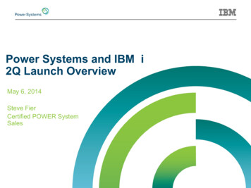
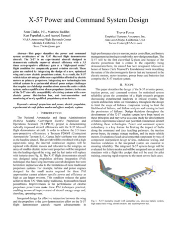
X-57 Power and Command System DesignSean Clarke, P.E., Matthew Redifer,Kurt Papathakis, and Aamod SamuelNASA Armstrong Flight Research CenterEdwards, California, USASean.Clarke@nasa.govAbstract—This paper describes the power and commandsystem architecture of the X-57 Maxwell flight demonstratoraircraft. The X-57 is an experimental aircraft designed todemonstrate radically improved aircraft efficiency with a 3.5times aero-propulsive efficiency gain at a “high-speed cruise”flight condition for comparable general aviation aircraft. Thesegains are enabled by integrating the design of a new, optimizedwing and a new electric propulsion system. As a result, the X-57vehicle takes advantage of the new capabilities afforded by electricmotors as primary propulsors. Integrating new technologies intocritical systems in experimental aircraft poses unique challengesthat require careful design considerations across the entire vehiclesystem, such as qualification of new propulsors (motors, in the caseof the X-57 aircraft), compatibility of existing systems with a newelectric power distribution bus, and instrumentation andmonitoring of newly qualified propulsion system devices.Keywords—aircraft propulsion and power, electric propulsion,experimental aircraft, failure modes and effects analysis, x-planeI.INTRODUCTIONThe National Aeronautics and Space Administration(NASA) Scalable Convergent Electric Propulsion andOperations Research (SCEPTOR) project is demonstratingradically improved aircraft efficiencies with the X-57 Maxwellflight demonstrator aircraft. In order to achieve the 3.5 timesaero-propulsive efficiencies, a Tecnam P2006T (CostruzioniAeronautiche Tecnam S.r.l., Capua, Italy) airframe was chosenas the baseline aircraft. The aircraft will be retrofitted with a highaspect-ratio wing, the internal combustion engines will bereplaced with electric motors and relocated to the wingtips, anarray of smaller electric motors and propellers will be integratedinto the leading edge of the wing, and the fuel tanks will replacewith batteries (see Fig. 1). The X-57 flight demonstrator aircraftwas designed using propulsion airframe integration (PAI)techniques that have long interested aircraft designers but wereheretofore impractical due to the limitations of more traditionalpropulsion systems. For example, turbine and piston enginesdesigned for the small scales required for these PAIopportunities cannot achieve specific power and efficiency ashigh as can larger systems. This condition reduces the gainsachieved from PAI when using traditional, hydrocarbon-basedpowertrains. Improvements in the performance of electricpropulsion powertrains make these PAI techniques practical,enabling an overall improvement of aircraft energy usage and,therefore, operating costs.Integrated design for effective interaction between the wingand the propellers is the core demonstration effort on the X-57flight demonstrator aircraft; recent advancements inTrevor FosterEmpirical Systems Aerospace, Inc.San Luis Obispo, California, USATrevor.Foster@ESAero.comhigh-performance electric motors, motor controllers, and batterymanagement technologies enable this new design paradigm. TheX-57 will be the first electrified X-plane and because of theelectric powertrain that is central to the capability beingdemonstrated here, the aircraft has been designated Maxwell inhonor of James Clerk Maxwell’s foundational work describingthe nature of the electromagnetic forces that are harnessed in theelectric motors, motor inverters, power buses and batteries thatcomprise the X-57 traction system.II.SCOPEThis paper describes the design of the X-57 avionics power,traction power, and command systems for optimized systemreliability given the constraints of a flight research programshowcasing experimental hardware in critical systems. Thesystem architecture relies on redundancy throughout the designto limit the scope of failures, component testing to limit thelikelihood of failures, and failure analysis and training to limitthe persistence of failures. Design decisions throughout thedevelopment of the X-57 traction system have been based onthese principles and may serve as a case study for developmentof future experimental aircraft and potential commercial aircraftexhibiting these technologies. Power and command systemredundancy is a key feature for limiting the impact of faultsalong the command and data handling pathways, the tractionpower buses, the energy storage medium, and the main vehiclemotors. Evaluation of each developmental component by way ofcomponent independent design review, endurance testing, andfunction validation in the integrated system are essential toensuring reliability. The integrated X-57 system design will beevaluated for failure modes and will be integrated into an aircraftsimulator with a flight-like cockpit that will be used for pilottraining, ensuring rapid response to the most severe fault cases.Fig. 1. X-57 Isometric model with centerline cut, showing battery system,high aspect ratio wing, electric motors, and traction power bus.
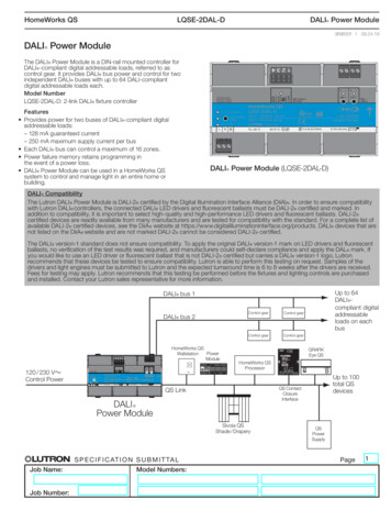
III.SYSTEM DESIGN OVERVIEWDevelopment of the X-57 research systems has been stagedinto four configurations (Mods I-IV), each of which increases incomplexity over the course of the research program. Thisapproach enables researchers to evaluate the baselineperformance and handling qualities of the unmodified aircraft inMod I, the experimental propulsion system dynamics andreliability in Mod II, the high-performance, high aspect-ratiowing in Mod III, and the distributed electric propulsion systemin Mod IV. By deploying the traction power, avionics power,and command systems in Mod II, the integrated systemperformance of these systems can be studied in a flight-provenairframe configuration with ample rudder authority and flexiblecenter of gravity (CG) placement. Thus, by the time the PAIfeatures are being evaluated in Mod III and Mod IV, theelectrical systems will be well understood and reliable as a resultof the extensive experience gained operating the traction power,avionics power, and command systems during the Mod IIground- and flight-testing program.The X-57 traction system beginning in Mod II consists oftwo independent battery packs, redundant power distributionbuses, and two cruise motors. Each cruise motor is rated for 255Nm and up to 2700 rpm (72 kW), shown in Fig. 2, and poweredby two independent motor torque controllers which convert theDC power provided by the batteries to switched AC power basedon the torque commanded by the pilot. Details of the cruisemotor design and development process are described in [1] and[2]. The battery packs are a custom design that uses commercialoff-the-shelf (COTS) lithium-ion 18650 cells arranged into fourlarge (approximately 100 lb.) modules per pack. Each of the twobattery packs supply approximately 23 kWh of usable capacityand operate independently from each other. In the event of afailure in one of the redundant systems, either pack can eachprovide sufficient power for a controlled return to base.Redundancy throughout the design of the traction power,avionics power, and command system is a critical tool forensuring minimum required thrust is available in the event ofany single fault condition on this experimental flightdemonstrator. Fig. 3 shows how the traction power systemredundancy approach has been used to design for twoindependent vehicle batteries, traction buses, and motor torquecontrollers for the main cruise motors. This approach is criticalFig. 2. The X-57 Cruise Motor prototype and variable-pitch propeller before atest run. Photograph credit Joby Aviation.for the X-57 design because the cruise power system is locatedat the wingtips in order to achieve improved propulsiveefficiency. Nominally, this wingtip configuration provides muchimproved performance of the main propellers, but thisconfiguration also increases the complexity of designing for thesingle-motor-out failure case because a failure of one of thecruise motors or propellers introduces a large yaw moment dueto asymmetric thrust. The redundancy approach of each of thesystems described in this paper limits the majority of thosefailure cases to compromising less than 50 percent of theavailable thrust at either cruise motor. Similarly, for the Mod IVDistributed Electric Propulsion (DEP) system driving 12propellers along the leading edge of the wing (six on each side)to achieve high lift at low airspeeds, a redundant architecture iscritical to reducing the severity of single-failure modes.Asymmetry in the induced velocity of air across the left wingversus the right wing can cause roll or yaw of the aircraft and aresultant loss of lift. The redundancy approach limits the effectsof these failures to primarily avoid asymmetric upsets, andsecondarily to limit the magnitude of the failure to no more thanthree of the propulsors for most cases (because no more thanthree of the motors in the DEP system on each side of the wingshare a bus).The traction and command systems developed for the X-57aircraft are intentionally kept as simple as possible to minimizethe development risks associated with complex systems and tosimplify testing and integration. Most of the components areCOTS products or are slightly modified from COTS products.Although the goal is to use parts that are of high technologyreadiness level (TRL) and already available in the marketplace,some such items are not suitable because of the demandingperformance requirements for the X-57 or because of specificapplication needs. The cruise motors and torque controllers arebeing developed for this vehicle by Joby Aviation (Santa Cruz,California). The main vehicle battery system is being developedby Electric Power Systems Inc. (Industry, California). The X-57acceptance and qualification test plan is designed to screen eachcomponent with a level of investigation appropriate toidentifying manufacturing defects and design flaws beforeintegration into the X-57.Fig. 3. X-57 Redundant Traction Power System.
IV.AVIONICS POWER SYSTEMThe X-57 avionics power system is designed to provide apiloting experience similar to that of the Tecnam P2006T, theaircraft from which the X-57 flight demonstrator is derived. Theapproach to the design involves maintaining as many of theexisting avionics systems as possible, allowing, to the extentsafely possible, the use of established procedures identified inthe relevant Pilot Operating Handbook. The stock configurationfollows the approach of many twin engine aircraft by crossstrapping the engine generator buses to a main bus which isbacked up by a battery. This method allows the operation ofesential aircraft avionics systems such as instruments, landinggear, and flaps in the event of many types of system power loss.The avionics power buses can be powered from either the left orright generator buses, or the battery backup. Loads can be shedby opening the cross-strap switches or the left and right avionicsbuses, affording the pilot many options in the event of variousavionics power system failures.The X-57 flight demonstrator follows the same approach,maintaining many of the existing switches, wiring, circuitbreakers, and relays of the Tecnam P2006T. As shown in the X57 avionics power system interconnect (Fig. 4), the left and rightgenerator buses are fed by the aircraft traction battery system.The traction battery consists of two battery packs (A and B).Because the battery packs have a nominal voltage of 461 VDC,the traction battery system implements two DC/DC buckconverters (one for each battery pack) to generate 14 VDCavionics power which feeds the left and right generator busesfrom the A and B batteries, respectively. Each buck converter issized for the entire avionics bus load. The stock aircraft backupbattery remains connected to the essential bus to provideessential avionics power in the event of a traction battery failureor shutdown. Avionics power can also be supplied from theaircraft external power socket for ground-testing operations.Notable differences between the Tecnam P2006T and theX-57 flight demonstrator are the instrumentation bus and thenew wing avionics buses. The instrumentation bus is fed fromthe aircraft right generator bus by way of a DC/DC boostconverter in order to generate 28 VDC used for instrumentation.The wing avionics buses A and B are added to facilitate theredundancy in the cruise motors. The dual core windings in thecruise motor are nominally powered by two separate cruisemotor controllers. Each wing avionics bus provides power to thecruise controllers in the left or right wing. Each motor controllerin the left and right wings is fed by the A and B battery packseparately via the wing avionics buses, allowing shutdown orfailure of either individual battery or wing avionics bus withcontinued operation of the motor at reduced power with oneremaining controller.To effectively communicate warnings to the pilot aboutfaults in the new avionics power and traction power systems, theTecnam P2006T annunciator panel was customized. The newannunciator panel configuration, is shown in Fig. 5. The A andB avionics warning lights are triggered by a fault indication fromthe DC/DC buck converters in the traction battery system. Atypical response to this warning would be to shut down theavionics side with the fault, and continue operations on theopposite side. A low-voltage indication from either of the mainFig. 4. The X-57 avionics power system interconnect.Fig. 5. The X-57 annunciator panel with electric propulsion system indication.traction battery sides is considered a critical fault. Depending onother factors, the response may be the shutdown of the offendingbattery side and immediate return to base with reduced motorperformance. These annunciator panel warnings are in additionto other warnings that are part of the command bus system,including fault notification via the multi-function display andaudio alarms.V.TRACTION POWER SYSTEMThe X-57 traction power system is designed to safely andreliably provide power to the motor torque controllers andensure that enough power would remain available to safely landthe aircraft in the event of single-point failures. This is achievedby using redundant power buses, physical separation of cablingand conduits, and electronically controlled power contactors forsafe operation of the motor controllers.While definitive guidelines exist for designing a safe andreliable traction power system, certified, airworthy electricaircraft propulsion systems for manned flight are a relativelynew design space. There is little precedent or documentation todefine proper standards. Existing Federal Aviation Regulations(FARs), such as Part 23 and Part 25, or Aeronautical Radio,Incorporated (ARINC) 400 series standards provide only basicwiring standards and limited guidance can be inferred fromturbine or gas engine regulations. Designing the X-57 tractionpower system necessitated evaluating the system as a whole toimplement standard aircraft features and capabilities. Once afunctional system was developed, the available standards werecombined with best practices to implement each subsystem.One such subsystem is the traction power cabling whichincludes standard aircraft features such as redundancy andisolation. The Mod II/III traction power bus for the X-57 is
divided into two independent A and B buses that are eachsubdivided between the left (A/L and B/L) and right (A/R andB/R) side of the aircraft, as shown in Fig. 3. Each bus (A andB) is independently powered by an electrically-isolated battery.This architecture provides redundancy to the cruise motors inthe event one of the buses fails. The buses are additionallyisolated from each other, within the wing, each bus runninginside dedicated conduits. This isolation aids in preventingcascading bus failures. Driving each cruise motor are two motortorque controllers, commonly referred to as the cruise motorcontroller (CMC). Each bus feeds one of the CMCs for onecruise motor. This technique follows the same redundant designphilosophy that given any single-point failure, each cruise motorcan still operate under the command of a single CMC.Contactor pallets are installed in the traction bus cablingbetween the batteries and the motors. There are two contactorpallets (A and B) located in the fuselage of the aircraftcorresponding to the associated A or B bus. Each pallet containssensors and electrical components to complete or interrupt thecircuit to the motor controllers. To safely power on the CMCsand avoid inadvertently energizing the traction bus in the wing,custom pre-chargers with integrated, aircraft-grade contactorsare used on the pallets. The pre-chargers control the voltage inthe traction bus to restrict the inrush current and the contactorsallow remote switching of the power from the traction bus.Current and voltage sensors within each pallet are used tomeasure the total energy consumption rate and total energyconsumed. Isolation of the A and B buses is maintained with twocontactor pallets physically placed on separate sides of theaircraft. This arrangement prevents failure of components withinone pallet from cascading to the other pallet.The wire used for the X-57 traction bus cable is unique inthat it is custom designed to address several challenges.Minimizing weight is inherently important, so using smallgauge wire is necessary. Wire that is too small, however, is asafety concern because of the potential for wires to overheat.Each electric cruise motor is designed to run at a total power of60 kW with each CMC nominally drawing 30 kW. The designof the X-57 batteries calls for lithium-ion cells in a series/parallelconfiguration combined with a depth-of-discharge limitationthat drives the voltage range between 416 VDC and 525 VDC.To size the traction cable, we assume that each bus (A/L, A/R,B/L, B/R) must carry 30 kW, which results in a current rangingfrom 57 A to 72 A for each bus. Derating factors for altitude andnumber of conductors in a bundle are determined using [3]which relates wire size (in American wire gauge, AWG) to theexpected temperature rise. The X-57 design uses four flat10-AWG conductors that are equivalent to 4-AWG as shown inFig. 6. These current limits only allow 4-AWG if the cable isable to reject heat to ambient air. If the air temperature is allowedto rise due to high-current operation of the wire, the 4-AWGwire may fail. In this design example, aerospace standards doexist, however, those standards fail to take into accountconsiderations from a systems perspective. This standardprovides a good first approximation, but model-drivenengineering (MDE) can refine the design further. Initialapplication of the SAE standard estimated that 2-AWG wouldbe required for nominal operation. Additionally, it is possible toover-drive the CMC in response to some system failures, whichwould require pulling more than the nominal design currentthrough a single bus. In this case, the SAE standard estimatesthat 2-AWG is required. Taking the MDE approach, aspecialized 4-AWG cable with a high-temperature jacket wasselected. The traction bus conduits are fabricated from athermally-conductive composite material and are thermallyisolated from the wing structure. In practice, the time spentoperating at elevated temperatures will be monitored and limitedas needed to prevent damage to the traction bus. Tests on thetraction bus cable with X-57 flight profiles are being conductedusing the NASA Electric Aircraft Testbed (NEAT) at the NASAGlenn Research Center (Cleveland, Ohio) in order to betterquantify the performance of the cable.Radiated electromagnetic interference (EMI) from thetraction bus is an additional design challenge, and can interferewith other systems on the vehicle. The traction system mayexhibit high frequency interference due to inverter switchingevents or lower frequency noise related to motor field rotation.To mitigate this, several traditional shielding methods wereconsidered, but the custom wing in the Mod III configurationhas very limited space, so it was not possible to use shielded #4AWG wires for the traction bus. However, the custom cabledescribed in Fig. 6 meets the space requirements. This cablecomprises four adjacent 10-AWG wires, creating a flat cablethat is four times wider than it is tall. The manufacturer claimsthat this configuration reduces the inductance and radiated noiseas compared to an equivalent round wire, and modeling of thesecable configurations supports this claim, as presented in Fig. 7.To test this performance, the NEAT facility conductedqualitative testing to assess radiated emissions on candidateFig. 6. The X-57 annunciator panel with electric propulsion system indication.Fig. 7. Near-field electric and magnetic field strength comparison betweentraditional two-conductor cable and the X-57 “flat cable” configuration.
cabling for the X-57 flight demonstrator. The NEAT test setuphas a 125-kW motor-inverter and DO-160 line impedancestabilization network equipped for radio frequency emissionmeasurement. Testing indicated that there was no significantdifference in radiated emissions between the baseline shieldedcable and the unshielded cables described in Table I; however,emissions are sensitive to the specific equipment being tested.The flat cable was selected because that cable fit the geometryrestrictions in the Mod III wing without noticeable EMIconcessions. There may be a benefit given the ability to tightlystack the supply and return cables to cancel radiated fields.VI.A.COMMAND SYSTEMOverviewThe X-57 command bus is used to control the electric motorsand provides aircraft health and status. The command flowconsists of throttle encoders (TEs) which digitize the existingTecnam throttle lever positions and the electric motorcontrollers, which use this position as a torque target. Thearchitecture of the bus follows the Controller Area Network(CAN) standard and includes both standard CAN messages andthe higher-level CANopen protocol. The CAN protocol offersvarious benefits including error detection, message arbitration,multicast reception, and prioritization [4]. The single-wire pairrequired for the CAN physical layer and a lack of a buscontroller simplify implementation. All devices on the X-57command bus adhere to the CAN2.0A standard and operate at1,000 kbaud. The CANopen system is a higher layer protocol,allowing configuration of nodes and defining the internal devicestructure of each device on the network [5]. Since CANopen isa higher layer of protocol built on CAN, components using theCANopen protocol can interoperate on a bus with componentsthat communicate with standard CAN messaging.The components of the command bus were selected basedon robustness and compatibility with the CAN bus. Becausesome components use the CANopen standard, precautions weretaken to ensure the components using the standard CANprotocol do not interfere with the additional functionality of theCANopen devices. The CANopen protocol uses a portion of themessage identification (first 4 bits of the message ID) of theCAN structure to identify configuration parameters and dataparameters. By considering the data parameter identifiers usedby CANopen, and carefully selecting the device identificationsboth for the CANopen and standard CAN devices, messagecollisions between the two standards is prevented. A diagram ofthe command system network is shown in Fig. 8.B.TABLE I.Cable123NEAT FACILITY EMI CABLE TEST MATRIXManufacturerChamplainTE ConnectivityMethodePart urationRound/ShieldRound/UnshieldFlat/Unshieldand the motor, including torque, speed, and temperatures, thatcan be used to provide situational awareness to the pilot.The MoTeC synchronous versatile input module (SVIM) isan analog to digital converter that transmits the data on a CANbus. These modules collect data at high rates (5000 samples persecond) and high resolution (15-bit) synchronously with othermodules as needed. For the X-57 application, these modules areused to record the blade pitch angle and temperatures associatedwith the CMCs and the motors. The size and capability totransmit on CAN make these devices useful in an EMIenvironment research capacity.The MoTeC Pty Ltd (Melbourne, Australia) D175 is afull-color, customizable display and is the main interfacebetween the pilot and the command bus. Fig. 9 shows s samplescreen of the display. These screens show health and statusinformation from the BMS, CMC, and TEs while also showingwarnings and alarms based on the values from these systems.The screens are toggled with switch inputs incorporated into thedisplay. Along with the situational awareness provided by thisFig. 8. The X-57 command system network diagram.ComponentsThe battery management system (BMS) is a custom solutionbuilt by Electric Power Systems (EPS). It uses a CANopenstandard that has been customized to fit with the X-57 CANarchitecture. The BMS provides battery health and statusinformation to the CAN bus, which can help convey relevantinformation to the pilot.The CMC is a custom solution provided by Joby Motors(Santa Cruz, California) and uses a CAN interface. The motorcontroller communicates health and status information for itselfFig. 9. The X-57 cockpit display reflects the duality of the X-57 systemdesign. Indicators include State of Charge, discharge rate, and throttle position.
display, the screens provide additional information that aid introubleshooting on the ground and quickly diagnosing problemsin the air. The two main pages for the pilot are toggled using asimple switch, while the remaining pages are accessed bycombining the switch with an eight-position rotary switch. Thissetup allows 16 different pages with information about thehealth and status of various X-57 components.A MoTeC advanced central logger (ACL) works as theprocessor for the display. The logger collects all of the relevantsignals, performs mathematical operations on them, and feedsthe results to the display. As such, the logger is used to determinethe health and status of the battery and motors and to provideany alarms or warnings to the pilot by way of the display. TheACL also controls the light-emitting diode (LED) lights on theD175 display that provide quick information to the pilot, such asbattery state-of-charge (SOC) or emergency location. Finally,the ACL serves as the interpreter for the SVIMs. The SVIMtransmits data on the CAN bus in a proprietary format that is noteasily interpreted by the instrumentation stack. Therefore, datathat come from the SVIM are read by the ACL and thenretransmitted to the command bus for the instrumentation stackto record. Since the instrumentation stack time-tags all the databeing recorded, there is an inherent delay between the time whenthe SVIM transmits the data and the instrumentation stackrecords the data after ACL retransmission. This delay isacceptable because of the slow rate of change of the data beingcollected by the SVIM.The two throttle encoders used in the project are Baumer Ltd.(Southington, Connecticut) rotary encoders that are CANopencompliant. These devices measure rotation of the stock Tecnamthrottle levers and put the data on the CAN bus. Each device alsohas dual encoders to provide greater reliability.Western Reserve Controls (WRC) (Akron, Ohio) fiber opticbus extenders (FOBEs) are commercial products that arecustomized for X-57 by repackaging for fit and robustnessrequirements. These bus extenders convert the electrical signalson the copper CAN bus to optical signals on fiber optic cablesand convert them back to electrical signals on a copper segmentcloser to remote CAN components. The distance of the CMCsfrom the rest of the CAN bus components, and their use of highcurrent to run the motors, present a higher risk of EMI in thecopper CAN bus segments. This risk is mitigated by separatingthe segments with FOBEs and fiber optic cables. Using fiberoptic cables also reduces the risk of reaching the line-lengthlimits of the CAN bus standard and susceptibility radiated EMIfrom the traction power bus.A CAN-controlled relay box is a product by Blink Marine(Milan, Italy) that allows relays to be opened and closed usingCAN messages. This provides an audio annunciator capabilitythat can provide key alarms to the X-57 pilot. These alarms aredefined collaboratively with the test pilots, system designers,and operations team. The audio annunciator works by groundingspecific inputs to the device, resulting in output in the form ofan audio message. CAN messages from the ACL to the relaybox energize relays which completes the circuit to theannunciator, allowing the ACL to determine any alarm statesand to alert the pilot both audibly (through the audioannunciator) and visually (through the D175 display). The audioannunciator that uses the relay box is a PRD60 accessory devicedeveloped by PS Engineering (Lenoir City, Tennessee). Thedevice contains six pre-programmed messages and the ability tomute messages by acknowledging them with a simplepush-button.The X-57 instrumentation system contains a CAN busmonitoring card that will interface to the command system. Thiscard is used to only listen to the traffic on the CAN bus andrecord all of that traffic with a time tag. A subset of thesemessages is also transmitted to the ground station.C.Risk MitigationThe X-57 command bus is considered a mission-criticalsystem, but not a safety-critical system. This designation ispossible because the pilot does not need to rely on the commandbus for the safe operation of the X-57 flight demonstratoraircraft. All of the safety-related information provided by theCAN bus is also independently measured and displayed on theright-hand instrument panel in the cockpit. The X-57 aircraft isalso designed with an unpowered reversion mode in which thepilot can safely control the aircraft and complete an unpowered,higher speed landing. This cap
avionics power, and command system is a critical tool for . the relevant Pilot Operating Handbook. The stock configuration follows the approach of many twin engine aircraft by cross-strapping the engine generator buses to a main bus which is ba