Transcription
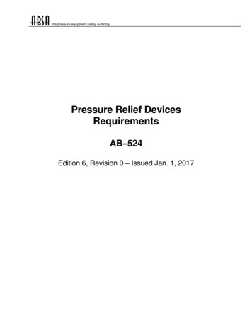
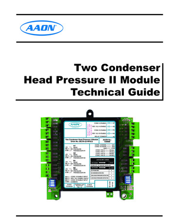
R2COND. B ENABLER3REV. VLV. B ENABLER4RELAY COMMONRCTwo Condenser Head Pressure II ModuleOrion No.:OE370-23-HP2C2 5VSIG 2GNDHEADPRESSURETRANSDUCER #2A2LED BLINK CODESB1 5VSIG 3GNDHEADPRESSURETRANSDUCER #3LED NAMELED NAMEB2HEADPRESSURETRANSDUCER #4BIN 1BIN 2BIN 3COMCOND. A ENABLE INPUTREV. VLV. ENABLE INPUTCOND. B ENABLE INPUTCOMMONWattMaster Label#LB102110-ARev.: 1ASTATBLINKS QTY. OF SENSORS INSTALLED 5VSIG 4GNDE-BUSConnectorAO1AO2GNDPWM1PWM1 PWM2PWM2 ALARMNO PROBLEMS0NO SENSORS DETECTED1HIGH HEAD PRESSURE DETECTED2LOW HEAD PRESSURE DETECTED3E-BUSConnectorGNDHEADPRESSURETRANSDUCER #1AAON No.:V20660COND. A SIGNALCOND. B SIGNALGNDCOND. FAN ACOND. FAN ACOND. FAN BCOND. FAN BA1 5VSIG 1GNDR1COND. A ENABLEREV. VLV. A ENABLE 24 VACwww.aaon.comRELAY CONTACTRATING IS 1 AMPMAX @ 24 VACTwo CondenserHead Pressure II ModuleTechnical Guide
ZoneTABLE OF CONTENTSZoneOVERVIEW . 3Overview . 3Features . 3INSTALLATION AND WIRING . 4Environmental Requirements . 4Mounting . 4Power Supply . 4Important Wiring Considerations . 4Stand-Alone Wiring . 5Condenser Type Selection . 5E-BUS Controller to Two Condenser Head Pressure II Module Wiring . 6SEQUENCE OF OPERATION . 8Inputs and Outputs. 8Stand-Alone Input Commands . 8Input Commands (VCM-X Connection) . 9Modes of Operation . 9TROUBLESHOOTING . 12Head Pressure Module Valve/Fan Position Troubleshooting . 12Troubleshooting for Stand Alone Mode . 13Pressure Transducer Troubleshooting . 14Using LEDs to Verify Operation . 14LED Diagnostics . 15Other Checks . 15PART NUMBER CROSS REFERENCE TABLEPART DESCRIPTIONORIONAAONTULSAAAONCOILTwo Condenser Head Pressure II Module - TulsaOE370-23-HP2C2V20660N/ATwo Condenser Head Pressure II Module - CoilOE370-23-HP2C2-CN/A31426VCM-X Modular E-BUS Controller - TulsaOE332-23E-VCMX-MOD-AV07150N/AVCM-X Modular E-BUS Controller - CoilOE332-23E-VCMX-MOD-CN/A30553VCM-X WSHP E-BUS Controller - TulsaOE332-23E-VCMX-WSHP-AV07140N/AVCM-X WSHP E-BUS Controller - CoilOE332-23E-VCMX-WSHP-CN/A30526SA E-BUS Controller - TulsaOE332-23E-SA-AV07160N/ASA Expansion Module - TulsaOE333-23-SA-AR96180N/Awww.aaon.comWattMaster Controls Inc.8500 NW River Park Drive · Parkville , MO 64152Toll Free Phone: 866-918-1100PH: (816) 505-1100 · FAX: (816) 505-1101E-mail: mail@wattmaster.comVisit our web site at www.orioncontrols.comCopyright April 2015 WattMaster Controls, Inc.AAON Manual Part Number: V22100AAON is a registered trademark of AAON, Inc., Tulsa, OK.WattMaster Form : AA-HP2C2-TGD-01ENeither WattMaster Controls, Inc. nor AAON assumes any responsibility for errors or omissions in thisdocument.This document is subject to change without notice.
INSTALLATION & WIRINGModule OverviewOverviewFeaturesThe Two Condenser Head Pressure II Module (OE370-23-HP2C2)monitors four individual head pressure transducers and controls twoCondenser Fans or Water Valves on units with two physically separatecondenser sections. The highest reading of head pressure transducers 1& 2 controls Condenser Signal A. The highest reading of head pressuretransducers 3 & 4 controls Condenser Signal B. If this is a heat pump unit,the module is able to detect when the unit is in Heat Pump Heating modeand will force the condenser signal to 100% until it leaves this mode.The Two Condenser Head Pressure II Module provides the following:The Two Condenser Head Pressure II Module is designed to workstand-alone by using its OPTIONS dip switch to adjust the Head Pressure setpoint.The Two Condenser Head Pressure II Module is directly connected tothe VCM-X Modular E-BUS, VCM-X WSHP E-BUS or SA E-BUSController, allowing the Module(s) to receive setpoints from the Controller. See chart on page 2 for part numbers. Can be operated stand alone or up to (2) modules can bedaisy-chained together and connected to a VCM-XModular E-BUS, VCM-X WSHP E-BUS, or SA E-BUSController Monitors up to four individual head pressure transducers Capable of monitoring a Reverse Valve SignalProvides control of Condenser Output Signals based on thehighest reading of head pressure transducersForces Condenser Fans to 100% while in the Heat PumpHeating ModeNOTE: The Two Condenser Head Pressure II Module containsno user-serviceable parts. Contact qualified technicalpersonnel if your Module is not operating correctly.When using the Two Condenser Head Pressure II Module with the RNEController, refer to the RNE Controller Technical Guide.The Two Condenser Head Pressure II Module also provides a pulsewidth modulation (PWM) signal or voltage output signal to control thecondenser fans.The Two Condenser Head Pressure II Module requires a 24 VAC powerconnection with an appropriate VA rating.RELAY CONTACTRATING IS 1 AMPMAX @ 24 VAC 5VSIG 1www.aaon.com 5VSIG 2 5VSIG 3GND 5VSIG 4R4RELAY COMMONRCHEADPRESSURETRANSDUCER #1 5VSIG 2GNDHEADPRESSURETRANSDUCER #2A2HEADPRESSURETRANSDUCER #3LED NAMELED NAMEB2HEADPRESSURETRANSDUCER #4BIN 1BIN 2BIN 3COMCOND. A ENABLE INPUTREV. VLV. ENABLE INPUTCOND. B ENABLE INPUTCOMMONWattMaster Label#LB102110-ARev.: 1AR3R4RcRELAYSANALOGAO1AO2GNDPWM1STATPWM1 BLINKS QTY. OF SENSORS INSTALLED 5VSIG 4GNDE-BUSConnectorAO1AO2GNDPWM1PWM1 PWM2PWM2 LED BLINK CODESB1 5VSIG 3GNDAAON No.:V20660COND. A SIGNALCOND. B SIGNALGNDCOND. FAN ACOND. FAN ACOND. FAN BCOND. FAN BCOMADDRESSREV. VLV. B ENABLEA1 5VSIG 1GNDBIN 2BIN 3R2Two Condenser Head Pressure II ModuleOrion No.:OE370-23-HP2C2GNDBIN 1R1R3ALARMNO PROBLEMS0NO SENSORS DETECTED1HIGH HEAD PRESSURE DETECTED2LOW HEAD PRESSURE DETECTED3E-BUSConnectorGNDGNDR2COND. B ENABLEPWM2PWM2 OPTIONS 24 VACGNDR1COND. A ENABLEREV. VLV. A ENABLEALARMSTATCOMMFigure 1: Two Condenser Head Pressure II ModuleTwo Condenser Head Pressure II Module Technical Guide3
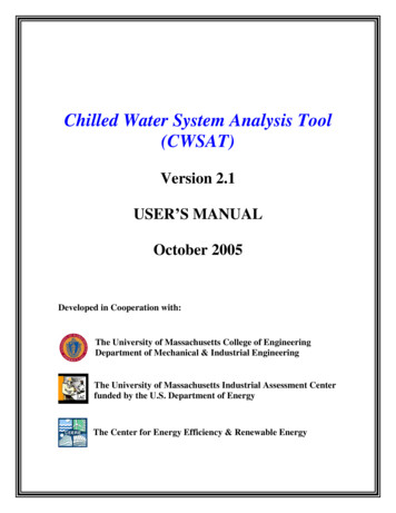
ZoneINSTALLATION & WIRINGZoneMounting and Wiring ConsiderationsEnvironmental RequirementsImportant Wiring ConsiderationsThe Two Condenser Head Pressure II Module needs to be installed inan environment that can maintain a temperature range between -30 Fand 150 F and not exceed 90% RH levels (non-condensing).Please read carefully and apply the following information when wiringthe Two Condenser Head Pressure II Module:MountingThe Two Condenser Head Pressure II Module is housed in a plasticenclosure. It is designed to be mounted by using the 3 mounting holesin the enclosure base. It is important to mount the module in a locationthat is free from extreme high or low temperatures, moisture, dust, anddirt. Be careful not to damage the electronic components when mounting the module.1. To operate the Two Condenser Head Pressure II Module, youmust connect power to the 24 VAC input terminal block.2. Each Pressure Transducer must have its own 18-gaugeshielded twisted pair cable. The Drain Wire must be the “Gnd”signal for the transducer.3. When the Analog Output is being used to control theCondenser Fan Speed or Water Valve Percentage, the cablemust be 18-gauge shielded wire, and the Drain Wire must bethe “Gnd” signal.4. If the Pulse Width Modulation (PWM) Output is being used todirectly control the ECM 142 motor, the wires do not need tobe shielded and can be any 18-gauge wire.See Figure 2 for Module dimensions (in inches).5.710.18 DIA. TYP.0.29SIG 1GNDwww.aaon.com 5VSIG 2SIG 3GND5.645.04 5VSIG 4GNDBIN 1BIN 2BIN 3R3REV. VLV. B ENABLER4RELAY COMMONRCTwo Condenser Head Pressure II ModuleOrion No.:OE370-23-HP2C2 5VSIG 1GNDHEADPRESSURETRANSDUCER #1A2 5VSIG 2GNDHEADPRESSURETRANSDUCER #2AAON No.:V20660AO1AO2GNDPWM1PWM1 PWM2PWM2 BLINKS QTY. OF SENSORS INSTALLEDB2LED NAME 5VSIG 4GNDHEADPRESSURETRANSDUCER #4BIN 1BIN 2BIN 3COMCOND. A ENABLE INPUTREV. VLV. ENABLE INPUTCOND. B ENABLE ETRANSDUCER #3LED NAMER2R4LED BLINK CODESB1 5VSIG 3GNDR1R3COND. A SIGNALCOND. B SIGNALGNDCOND. FAN ACOND. FAN ACOND. FAN BCOND. FAN BA1STATALARMNO PROBLEMS0NO SENSORS DETECTED1HIGH HEAD PRESSURE DETECTED2LOW HEAD PRESSURE DETECTED3PWM1 PWM2PWM2 OPTIONSCOMADDRESSR2COND. B ENABLEE-BUSConnectorWattMaster Label#LB102110-ARev.: 1AE-BUSConnectorGND 5VR1COND. A ENABLEREV. VLV. A ENABLE 24 VACGNDRELAY CONTACTRATING IS 1 AMPMAX @ 24 VAC 5VALARMSTATCOMM2.070.554.14Figure 2: Two Condenser Head Pressure II Module Dimensions4Two Condenser Head Pressure II Module Technical Guide
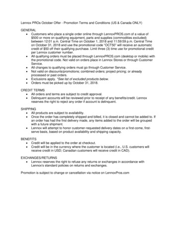
INSTALLATION & WIRINGStand-Alone WiringStand-Alone Wiring5. Check all wiring leads at the terminal block for tightness.Be sure that wire strands do not stick out and touch adjacentterminals. Confirm that all transducers required for yoursystem are mounted in the appropriate location and wired intothe correct terminals.WARNING:To operate the Two Condenser Head Pressure II Module as Stand Alone,connect the Module to a 24 VAC connection with an appropriate VArating. See Figure 3 for wiring.Check all wiring leads at the terminal block for tightness. Be sure thatwire strands do not stick out and touch adjacent terminals. Confirm thatall transducers required for your system are mounted in the appropriatelocation and wired into the correct terminals.Be sure all controllers and modules arepowered down before connecting ordisconnecting HSSC cables.Condenser Type SelectionAs shown in Figure 3, set ADDRESS Dip Switch 1 to ON for watercooled or to OFF for air cooled. Refer to page 8 for further instructions.HVAC UNIT CONNECTIONNOTE: ALL RELAY OUTPUTSARE NORMALLY OPEN ANDRATED FOR 24 VAC POWERONLY - 1 AMP MAXIMUM LOADCONDENSER A ENABLEREVERSING VALVE A ENABLECONDENSER B ENABLEREVERSING VALVE B ENABLEOE370-23-HP2C2Two Condenser Head Pressure II ModuleCondenserSignal AHead Pressure Transducers0 - 667 PSI(One Per Refrigerant Circuit) VSIGGNDRDWHBK VSIGGNDSIG 2 5VSIG 3GND 5VSIG 4GNDBIN 1BIN 2CONDENSER B ON/OFFCOMSet ADDRESS Dip Switch 4 to OFFto make reversing valve "ON toHeat / OFF to Cool.” Set to ON tomake reversing valve “ON to Cool /OFF to Heat.” Currently showingOFF.REV. VLV. B ENABLER4R3RELAY COMMONRCTwo Condenser Head Pressure II ModuleOrion No.:OE370-23-HP2C2HEADPRESSURETRANSDUCER #1 5VSIG 2GNDHEADPRESSURETRANSDUCER #2A2HEADPRESSURETRANSDUCER #3LED NAMERcSTATCondenserSignal B RELAYSCOMANALOGAO1AO2Condenser Fan AECM MotorGNDPWM1-YELLOWPWM1 BLUE 24 OUTLED NAMEHEADPRESSURETRANSDUCER #4ALARMPWM2-NO PROBLEMS0PWM2 NO SENSORS DETECTED1HIGH HEAD PRESSURE DETECTED2LOW HEAD PRESSURE DETECTED3YELLOWBLUE 24 OUTBIN 3COMADDRESSBIN 1BIN 2BIN 3COMCOND. A ENABLE INPUTREV. VLV. ENABLE INPUTCOND. B ENABLE INPUTCOMMONE-BUSConnectorWattMaster Label#LB102110-ARev.: 1ADuty Cycle 24 VoltsBLINKS QTY. OF SENSORS INSTALLEDB2 5VSIG 4GNDAO1AO2GNDPWM1PWM1 PWM2PWM2 LED BLINK CODESB1 5VSIG 3GNDR4AAON No.:V20660COND. A SIGNALCOND. B SIGNALGNDCOND. FAN ACOND. FAN ACOND. FAN BCOND. FAN BA1 5VSIG 1GNDR1R2R3R4COMME-BUSConnectorCondenser Fan BECM MotorOPTIONSSet ADDRESS Dip Switch 3 to ONto disable Circuit B alarms whenonly one Condenser is Used.Currently showing OFF.R2GNDCONDENSER A ON/OFFADDRESS Dip Switch 2 is not usedin this application.R1R3 5VREVERSING VALVE A/B ON/OFFSet ADDRESS Dip Switch 1 to ONfor Water Cooled or to OFF for AirCooled. Currently showing OFF forAir Cooled.R2COND. B ENABLEGND VSIGGNDGNDREV. VLV. A ENABLE 24 VACRDWHBKwww.aaon.comSIG 1Duty Cycle 24 VoltsALARMSTATCOMMOPTIONS Dip Switch isUsed for Setting the HeadPressure Setpoint if NotUsing Default Setpoint.PWR24 VAC VSIGGND 5VGNDRDWHBKRELAY CONTACTRATING IS 1 AMPMAX @ 24 VACRDWHBK COMR1COND. A ENABLELine VoltageWARNING!!Observe Polarity! All boardsmust be wired with GND-to-GNDand 24 VAC-to-24 VAC. Failureto observe polarity could result indamage to the boards.24 VAC Transformer3 VA MinimumFigure 3: Two Condenser Head Pressure II Module Wiring Diagram (Stand-Alone)Two Condenser Head Pressure II Module Technical Guide5
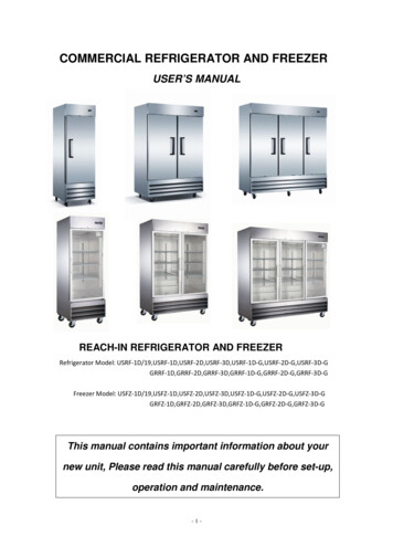
ZoneINSTALLATION & WIRINGZoneE-BUS Controller to Two Condenser Head Pressure II Module WiringVCM-X Modular E-BUS, VCM-X WSHPE-BUS or SA E-BUS Controller to TwoCondenser Head Pressure II ModuleWiringAny E-BUS Module can be connected to the E-BUS Controller’s E-BUSport or can be daisy-chained together using HSSC cables.NOTE: Contact Factory for the correct HSSC cable length foryour application. Cables are available in ¼, ½, 1, 2, 3,4, and 5 Meter lengths and 100 and 150 Foot lengths.Up to (2) Two Condenser Head Pressure II Modules can be daisy-chainedtogether and connected to the E-BUS Controller using a modular HSSCcable. The Two Condenser Head Pressure II Module requires a 24 VACpower connection with an appropriate VA rating. See Figure 4 belowfor wiring.HVAC UNIT CONNECTIONNOTE: ALL RELAY OUTPUTSARE NORMALLY OPEN ANDRATED FOR 24 VAC POWERONLY - 1 AMP MAXIMUM LOADCONDENSER A ENABLEREVERSING VALVE A ENABLECONDENSER B ENABLEREVERSING VALVE B ENABLEOE370-23-HP2C2Two Condenser Head Pressure II ModuleCondenserSignal AHead Pressure Transducers0 - 667 PSI(One Per Refrigerant Circuit)RDWHBK VSIGGNDRDWHBK VSIGGNDGNDR2R1COND. B ENABLER3R2REV. VLV. B ENABLER4RELAY COMMONRC 5VSIG 2Two Condenser Head Pressure II ModuleOrion No.:OE370-23-HP2C2GND 5VSIG 3GND 5VSIG 4GNDBIN 1BIN 2HEADPRESSURETRANSDUCER #1A2 5VSIG 2GNDHEADPRESSURETRANSDUCER #2HEADPRESSURETRANSDUCER #3LED NAMECOMCondenserSignal B RELAYSCOMANALOGAO1Condenser Fan AECM MotorAO2GNDDuty CyclePWM1-BLUE 24 OUTSTATLED NAMEB2HEADPRESSURETRANSDUCER #4BIN 1BIN 2BIN 3COMCOND. A ENABLE INPUTREV. VLV. ENABLE INPUTCOND. B ENABLE INPUTCOMMONE-BUSConnectorRcPWM1 5VSIG 4GNDWattMaster Label#LB102110-ARev.: 1AR4 24 VoltsBLINKS QTY. OF SENSORS INSTALLEDBIN 3ADDRESSR3YELLOWLED BLINK CODESB1 5VSIG 3GNDAO1AO2GNDPWM1PWM1 PWM2PWM2 COND. A SIGNALCOND. B SIGNALGNDCOND. FAN ACOND. FAN ACOND. FAN BCOND. FAN BA1 5VSIG 1GNDAAON No.:V20660R1R2R3R4COMMALARMNO PROBLEMS0NO SENSORS DETECTED1HIGH HEAD PRESSURE DETECTED2LOW HEAD PRESSURE DETECTED3E-BUSConnectorYELLOWBLUE 24 OUTPWM2PWM2 Condenser Fan BECM MotorOPTIONSSet ADDRESS Dip Switch 1 to ON forWater Cooled or to OFF for Air Cooled.Currently showing OFF for Air Cooled.Set ADDRESS Dip Switch 2 to OFFon all communicating applicationsunless it is intended to be the SecondHead Pressure Module on a system. Ifset to ON, it will not communicate.Currently showing OFF.REV. VLV. A ENABLEGND VSIGGNDwww.aaon.comSIG 1 24 VACRDWHBK 5VDuty Cycle 24 VoltsALARMSTATCOMMOPTIONS Dip Switch Setting Not RequiredWhen Connected ToVCM-X E-BUS Controlleror SA E-BUS ControllerPWRGNDSet ADDRESS Dip Switch 3 to ON todisable Circuit B alarms when only oneCondenser is Used. Currently showingOFF.24 VAC VSIGGNDRELAY CONTACTRATING IS 1 AMPMAX @ 24 VACRDWHBK COMR1COND. A ENABLESet ADDRESS Dip Switch 4 to OFF tomake reversing valve "ON to Heat /OFF to Cool.” Set to ON to makereversing valve “ON to Cool / OFF toHeat.” Currently showing OFF.Line Voltage24 VAC Transformer3 VA Minimum.Connect To OtherWattMaster-ApprovedE-BUS Expansion Module(s)HSSC CableHSSC CableConnect To VCM-X E-BUSController or SA E-BUS ControllerWARNING!! Observe Polarity! All boardsmust be wired with GND-to-GND and 24VAC-to-24 VAC.Failure to observe polarity could result indamage to the boards.Figure 4: VCM-X E-BUS Controller to Two Condenser Head Pressure II Module Wiring Diagram6Two Condenser Head Pressure II Module Technical Guide
INSTALLATION & WIRINGE-BUS Controller to Two Condenser Head Pressure II Module WiringWARNING:Be sure all controllers and modules arepowered down before connecting ordisconnecting HSSC cables.For Stand Alone Applications,Connect To System Manager. For NetworkApplications Connect To Next ControllerAnd/Or MiniLink PD On Local Loop.Note:All Relay Outputs Are Normally Open AndRated For 24 VAC Power Only.1 Amp Maximum Load.OE332-23E-VCMX-MODVCM-X ModularE-BUS ControllerLocal LoopRS-4859600 BaudRS-485 COMMUNICATION LOOP. WIRE“R” TO “R”, “T” TO “T” “SHLD” TO “SHLD”R - 24VACRELAY CONTACTRATING IS 1 AMPMAX @ 24 VACG - Fan ON/OFF OnlyRELAYCOMMONAll Comm Loop Wiring IsStraight ThruT to T, R to R & SHLD to SHLDFANRELAY 2RELAY 3RELAY 4RELAY 5Relay Output ContactsR2 Through R5 May Be User-ConfiguredFor The Following:1 - Heating Stages2 - Cooling Stages3 - Warm-up Mode Command (VAV Boxes)4 - Reversing Valve (Air To Air Heat Pumps)5 - Reheat Control (Dehumidification)6 - Exhaust Fan Interlock7 - Preheater For Low Ambient Protection8 - Alarm9 - Override10 - Occupied11 - OA Damper12 - Heat Wheel13 - Emergency HeatNote: 1.) When Using the HP2C Module,All Compressors Will Be Wired From theProtection Module, Not the VCM-X Controller.Note: A Total Of 20 Relays Are Available ByAdding Relay Expansion Modules. AllExpansion Module Relay Outputs Are UserConfigurable As Listed Above.AAON No.:V07150VCM-X MODULAR E-BUS CONTROLLEROrion No.:OE332-23E-VCMX-MOD-AAI1 SPC (SPACE TEMPERATURE SENSOR)AI2 SAT (SUPPLY AIR TEMPERATURE SENSOR)AI3 RAT (RETURN AIR TEMPERATURE SENSOR)AI4 OAT (OUTDOOR AIR TEMPERATURE SENSOR)AI5 SUCTION PRESSURE SENSOR (FROM EXP. MODULE)AI7 SPACE TEMPERATURE SENSOR SLIDE ADJUSTOR VOLTAGE RESET SOURCEA01 ECONOMIZER (2-10 VDC OUTPUT)A02 SUPPLY FAN VFD (0-10 VDC OUTPUT)HSSC Cable Connect ToVCM-X E-BUS PortE-BUSCONNECTORANALOG INPUTJUMPERSETTINGSAI1 SETSee IndividualComponent WiringDiagrams ForDetailed Wiring OfAnalog Inputs AndLED BLINK CODESSTATUS1STATUS2NORMAL OPERATIONLED NAME01SAT FAIL1OAT FAIL2SPC FAIL32MODULE ALARM42AI2 ERM4-20mA0-10V0-5VTHERM4-20mA0-10V0-5VPUSH BUTTON OVR15AI7ZONE OVR25OUTPUT FORCE ACTIVE062MECH COOL FAIL13MECH HEAT FAIL23FAN PROOF FAIL33DIRTY FILTER43EMERGENCY SHUTDOWN53LOW SAT14HIGH SAT24CONT. TEMP COOL FAIL34CONT. TEMP HEAT FAILAI3 SETANALOG INPUT JUMPER SETTINGSMUST BE SET AS SHOWN FORPROPER OPERATIONSTATICPRESSURE2WattMaster Label#LB102073-01-ARev.: 1A44GNDLine Voltage24 VAC POWER ONLYWARNING! POLARITY MUST BE OBSERVEDOR THE CONTROLLER WILL BE DAMAGED2ICEXPANSION24VAC2IC DIGITALSENSORAI4 SETSize Transformer For CorrectTotal Load.VCM-X Controller 8 VAJumpersAI5 SETSplice If RequiredConnect To Digital Room Sensor And/OrDigital CO2 SensorAI7 SETConnect ToExpansion Module(s)(When Used)OE271Static PressureTransducerWarning:24 VAC Must Be Connected So That All GroundWires Remain Common. Failure To Do So WillResult In Damage To The Controllers.Connect FRP Tubing To High PressurePort (Bottom Tube) and Route To StaticPressure Pickup Probe Located In UnitDischarge. Leave Port Marked “Lo” OpenTo AtmosphereFigure 4, cont.: VCM-X E-BUS Controller to Two Condenser Head Pressure Module II Wiring DiagramTwo Condenser Head Pressure II Module Technical Guide7
SEQUENCE OF OPERATIONStand-Alone Input CommandsZoneZoneGeneralStand-Alone Input CommandsThe following inputs and outputs are available on the Two CondenserHead Pressure II Module. See Table 1 below to reference the Input/Output Map.Condenser Fan A On/OffBinary Inputs1Condenser Fan A On/Off (24 VAC Wet Input)2Reversing Valve On/Off (24 VAC Wet Input)3Condenser Fan B On/Off (24 VAC Wet Input)Binary Outputs1Condenser A Enable Relay(Dry Contact Output Rated for 24 VAC)2Reversing Valve A Enable(Dry Contact Output Rated for 24 VAC)3Condenser B Enable Relay(Dry Contact Output Rated for 24 VAC)4Reversing Valve B Enable(Dry Contact Output Rated for 24 VAC)Analog Inputs1Head Pressure #1 (0-667 PSI Sensor)2Head Pressure #2 (0-667 PSI Sensor)3Head Pressure #3 (0-667 PSI Sensor)4Head Pressure #4 (0-667 PSI Sensor)A 24 volt signal to Binary Input #1 initiates the Condenser Fan A Enablefunction. Typically, the source for this signal is the “Y” call from thethermostat calling for a compressor to run.Reversing Valve On/OffA 24 volt signal to Binary Input #2 indicates the reversing valve hasbeen energized and initiates the Reversing Valve Enable On indicationfunction. Typically, the source for this signal is the “O” call from athermostat or other controller.Condenser Fan B On/OffA 24 volt signal to Binary Input #3 initiates the Condenser Fan B Enablefunction. Typically, the source for this signal is the “Y” call from thethermostat calling for a compressor to run.Head Pressure SetpointThe Head Pressure Setpoint is set using the OPTIONS Dip Switches. SeeTable 2. The Default Setpoint for an Air Cooled Condenser is 340 for410-A refrigerant. The Default Setpoint for a Water Cooled Condenseris 235 for 410-A refrigerant. Set the OPTIONS Dip Switch to 0 if usingthese Default Settings. See “ADDRESS Dip Switch” below. You mustcycle power after setting Dip Switch values.NOTE: The only setpoint available for adjustment by the contractor is the Head Pressure Setpoint. The rest of thesetpoints described can only be changed by the factory.Analog Outputs (0-10 or 2-10 VDC)1Condenser Signal A (AOUT 1)2Condenser Signal B (AOUT 2)PWM Inputs1ECM 142 PWM Input (0-100% Duty Cycle)2ECM 142 PWM Input (0-100% Duty Cycle)ADDRESS Dip Switch Settings for CondenserType SelectionWhen using the OPTIONS Dip Switch to set the Head Pressure Setpoint,you must also set the ADDRESS Dip Switch to designate the type ofcondenser you are using.Set ADDRESS Dip Switch 1 to ON for a Water Cooled Condenser orto OFF for an Air Cooled Condenser.Table 1: Two Condenser Head Pressure II ModuleInputs & OutputsIf set to ON for a Water Cooled Condenser, the Analog Condenser OutputSignal will be 2-10 VDC for the Water Valve. If set to OFF for an AirCooled Condenser, the Analog Condenser Output Signal will be 0-10VDC for the Condenser Fan.You must cycle power after setting Dip Switch values. See Figure3 or 4 for ADDRESS Dip Switch location and Table 3 for Settinginformation.8Two Condenser Head Pressure II Module Technical Guide
SEQUENCE OF OPERATIONVCM-X Input Commands and Modes of OperationInput Commands (VCM-X Connection)Modes of OperationCondenser A & B On/OffOFF ModeInstead of a hard wired input signal to the Condenser Enable input,the VCM-X Modular Controller, VCM-X WSHP Controller, or SAController communicates to the Module via E-BUS communications.This signal indicates the compressor(s) are called to run and drives thecondenser A & B On/Off function.The Head Pressure Control Board is in the OFF Mode when the Condenser Input Signals are “OFF.” In this mode, all relays are off, theAnalog Output is 0 VDC, and the PWM Output is 0% Duty Cycle.Reversing Valve Enable A & B On/OffIf the Head Pressure Controller has been configured for the ReversingValve to be energized in the Cooling Mode and to Fail to the Heat Mode(Dipswitch 4 is set ON), then the Head Pressure Controller will be inthe Cooling Mode when one or both of the Condenser Signal inputs is“ON” and the Reversing Valve Enable Signal is “ON”. In this circumstance, the Reversing Valve Enable Relay Output(s) will energize forindication purposes.As with the Condenser Signal On/Off function, the VCM-X ModularController, VCM-X WSHP Controller, or SA Controller communicatesto the Module via E-BUS communications and signals that the reversingvalve has been energized and that heating has been enabled.NOTE: When the term “ON” is used, it means there is either 24VAC on the appropriate Binary Input or a call-to-runsignal is being received from a VCM-X series or SAseries controller. When the term “OFF” is used, it meansthere is either 0 VAC on the appropriate Binary Input orthe call-to-run signal from a VCM-X series or SA seriescontroller has been removed.Sensor Reading RoutineThe Two Condenser Head Pressure Module is used on units with twophysically separate condenser sections. Up to (2) Head Pressure Sensorscan be monitored in each section. The highest of the two readings ineach section will be used to control the condenser fan(s) in that section.Air from the condenser fan(s) in each section flows through both condenser coils. As a result, if you modulate the fan(s) based on the highestreading, you will have enough air flow for both coils.The highest reading of Head Pressure Sensors 1 & 2 controls CondenserFan A. The highest reading of Head Pressure Sensors 3 & 4 controlsCondenser Fan B.Cooling ModeIf the Head Pressure Controller has been configured for the ReversingValve to be energized in the Heating Mode and to Fail to the Cool Mode(Dipswitch 4 is set OFF), then the Head Pressure Controller will be inthe Cooling Mode when one or both of the Condenser Signal inputs is“ON” and the Reversing Valve Enable Signal is “OFF”.The Condenser Enable Relays will energize to enable the CondenserFans or Water Valves. In a water system, the Water Flow Valve willstart at 75% for 3 minutes. The Condenser Output Signals will thenautomatically adjust between 0 and 100% to maintain the desired HeadPressure Setpoint. The Condenser Output Signals can be a 0-10 VDC,2-10 VDC or 0-100% PWM signal provided by the appropriate output.Both outputs mirror each other.Heating ModeIf the Head Pressure Controller has been configured for the ReversingValve to be energized in the Cooling Mode and to Fail to the Heat Mode(Dipswitch 4 is set ON), then the Head Pressure Controller will be inthe Heating Mode when one or both of the Condenser Signal inputs is“ON” and the Reversing Valve Enable Signal is “OFF”.If the Head Pressure Controller has been configured for the ReversingValve to be energized in the Heating Mode and to Fail to the Cool Mode(Dipswitch 4 is set OFF), then the Head Pressure Controller will be inthe Cooling Mode when one or both of the Condenser Signal inputs is“ON” and the Reversing Valve Enable Signal is “ON”. In this circumstance, the Reversing Valve Enable Relay Output(s) will energize forindication purposes.In this mode, the Condenser Output Signals will go to 100% and remainthere until it leaves the Heating Mode.NOTE: The Reversing Valve Dipswitch 4 setting determineswhether the Reversing Valve Dipswitch 4 Relay is ONto Heat / OFF to Cool or ON to Cool / OFF to Heat.NOTE: The Reversing Valve Enable outputs are for indicationonly and are not wired to anything.Two Condenser Head Pressure II Module Technical Guide9
ZoneSEQUENCE OF OPERATIONZoneOPTIONS Dip Switch SettingsOPTIONS DipSwitch SettingsHead Pressure SetpointAir Cooled CondenserWater Cooled CondenserBinary ValueR410-AR410-A0340 (DEFAULT)235 03301439034015400350Table 2: OPTIONS Dip Switch/Head Pressure Setpoint Settings for Stand-Alone OperationADDRESS Dip Switch 1 SettingsSwitch 1Default SPDescription of Default Head Pressure SetpointOFF340Air Cooled Condenser using R410-A RefrigerantON235Water Cooled Condenser using R410-A RefrigerantSwitch 1 determines Air or Water Cooled CondenserNOTE: You must cycle power after setting Dip Switch values.Table 3: ADDRESS Dip Switch 1 Condenser Type Settings10Two Condenser Head Pressure II Module Technical Guide
SEQUENCE OF OPERATIONOPTIONS Dip Switch SettingsADDRESS Dip Switch 2 SettingsSwitch 2DescriptionOFFSet to OFF if Using only (1) Head Pressure Moduleor if this is Module 1 when Using (2) Head PressureModules.ONSet to ON if this is Module 2 when Using (2) HeadPressure Modules.Table 4: ADDRESS Dip Switch 2 Address Settings When in Communicating ModeADDRESS Dip Switch 3 SettingsSwitch 3DescriptionOFFEnable Circuit B AlarmONDisable Circuit B Alarm when only one condenser isused.Table 5: ADDRESS Dip Switch 3 SettingsADDRESS Dip Switch 4 SettingsSwitch 4DescriptionOFF
wattmaster label #lb102110-a rev.: 1a e-bus connector e-bus connector 5v sig 1 gnd 5v sig 2 gnd 5v sig 3 gnd 5v sig 4 gnd gnd c bin 1 bin 2 bin 3 com head pressure transducer #1 head pressure transducer #2 head pressure transducer #3 head pressure transducer #4 rev. vlv. enable input common pwm2 aaon no.: v20660 ao1 ao2 gnd cond. a enable .