Transcription
TechnicalInformationHandbookWire and CableFifth Edition Copyright 2018
Trademarks and Reference InformationThe following registered trademarks appear in this handbook:Alumel is a registered trademark of Concept Alloys, LLCChromel is a registered trademark of Concept Alloys, LLCCopperweld is a registered trademark of Copperweld Steel CompanyInformation in this handbook has been drawn from manypublications of the leading wire and cable companies in theindustry and authoritative sources in their latest availableeditions. Some of these include:CSA is a registered trademark of the Canadian Standards Association American Society for Testing and Materials (ASTM)CCW is a registered trademark of General Cable Corporation Canadian Standards Association (CSA)DataTwist is a registered trademark of Belden Institute of Electrical and Electronics Engineers (IEEE)Duofoil is a registered trademark of BeldenFlamarrest is a registered trademark of Belden Insulated Cable Engineers Association (ICEA)Halar International Electrotechnical Commission (IEC)is a registered trademark of Solvay SolexisHypalon is a registered trademark of E. I. DuPont de Nemours & CompanyHypot is a registered trademark of Associated Research, Inc.IBM is a registered trademark of International Business Machines Corporation National Electrical Manufacturers Association (NEMA) National Fire Protection Association (NFPA)Kapton is a registered trademark of E. I. DuPont de Nemours & Company Naval Ship Engineering Center (NAVSEC)Kevlar is a registered trademark of E. I. DuPont de Nemours & Company Telecommunications Industry Association (TIA)K FIBER is a registered trademark of General Cable CorporationKynar is a registered trademark of Arkema, Inc.Loc-Trac is a registered trademark of Alpha WireMegger is a registered trademark of Megger Group Ltd.Mylar is a registered trademark of E. I. DuPont de Nemours & CompanyNEC is a registered trademark of the National Fire Protection AssociationNicrosil is a registered trademark of Harrison Alloys, Inc.Nisil is a registered trademark of Harrison Alloys, Inc.Nomex is a registered trademark of E. I. DuPont de Nemours & CompanyPolywater is a registered trademark of American Polywater CorporationScotch is a registered trademark of 3MScotchlok is a registered trademark of 3MSolef is a registered trademark of Solvay SolexisTeflon is a registered trademark of E. I. DuPont de Nemours & CompanyTefzel is a registered trademark of E. I. DuPont de Nemours & CompanyTyrin is a trademark of Dow Chemical CompanyUL is a registered trademark of Underwriters Laboratories, Inc.UniBlend is a registered trademark of General Cable CorporationUniShield is a registered trademark of General Cable CorporationUniStrand is a registered trademark of Belden Inc.Valox is a registered trademark of General Electric CompanyZ-Fold is a registered trademark of BeldenZytel is a registered trademark of E. I. DuPont de Nemours & CompanyII Underwriters Laboratories (UL).Note: National Electrical Code (NEC) is a registered trademark ofthe National Fire Protection Association, Quincy, MA. The term,National Electrical Code, as used herein, means the triennialpublication constituting the National Electrical Code and is usedwith permission of the National Fire Protection Association.
PrefaceThe WireXpress Wire and Cable Technical Handbook is an easily accessible collection of engineering and technical information about electricaland electronic cable and their related products. Primarily intended for individuals who design, specify or troubleshoot wire and cable systems,the WireXpress Wire and Cable Technical Information Handbook contains information about topics such as: Basic principles of electricity Conductor, insulation and jacket materials along with their electrical and mechanical properties Cable types, selection criteria and application guidelines for electrical and optical wire and cable Installation and testing guidelines and recommendations Application tips for cable accessories such as connectors, lugs and terminations Packaging, handling and shipping guidelines References to hundreds of key domestic and international wire and cable standards Conversion tables (e.g., AWG to mm2) and basic engineering equations used in the industryThe information contained in this handbook will assist engineers and individuals in designing and constructing safe, reliable, cost-effective andenvironmentally responsible electrical and communications networks.WireXpress wishes to acknowledge the contributions of the many individuals who assisted in the preparation of this edition of the handbook.WireXpress especially wants to recognize the efforts of Deborah Altman, Dana Anderson, Harmony Merwitz, Eric Bulington, Mark Fordham, JeffGronemeyer, Andy Jimenez, Jason Kreke, Jonathan Meyer, Nader Moubed, Ania Ross, Eric Wall and Bill Wilkens.WireXpress hopes it has succeeded in making this handbook the best in the industry and welcomes your comments and suggestions forimprovements in future editions. If you are interested in downloading the PDF version of this book, please visit WireXpress.com.ABOUT WIREXPRESSWireXpress is a master distributor of electrical and electronic wire and cable, datacomm, security and A/V, industrial networking and controls,and all of the related support products.We help you sell more by listening to your needs, developing solutions, and providing quality products and services.III
IV
ContentsCONTENTSTrademarks and Reference InformationIIPrefaceIIIAbout WireXpressIII1.Basic Principles of Electricity11.1 Electricity1.2 The Volt1.3 The Ampere1.4 The Ohm1.5 Ohm’s Law1.6 Ampacity1.7 Electrical Systems2222223Conductors52.3.2.1 Strand Types2.2 Coatings2.3 Tensile Strength of Copper Wire2.4 Copper Strand Properties2.5 Aluminum Strand Properties2.6 Additional Conductor Properties71010112226Insulation and Jacket Materials333.1 Purpose3.2 Types and Applications3.3 Color Coding3.4 Properties34343847V
Contents4.5.6.7.Shields554.1 Power Cable4.2 Electronic Cable5658Armor615.1 Interlocked Armor5.2 Continuously Corrugated and Welded (CCW)5.3 Basket-Weave5.4 Lead Sheath5.5 Wire Serve6262636363Cable Types and Selection Criteria656.1 Portable Power and Control6.2 Construction and Building Wire6.3 Control, Instrumentation and Thermocouple6.4 High Temperature6.5 Power6.6 Armored Power and Control6.7 Electronic Cable6.8 Telephone6.9 Military6.10 Shipboard Cables (MIL-DTL-24643, MIL-DTL-24640 and MIL-DTL-915)6.11 Optical Fiber Cables6.12 Tray Cables676868707173737880818184Electrical Characteristics857.1 DC Resistance of Plated Copper Conductors7.2 DC and AC Resistance of Copper Conductors7.3 DC and AC Resistance of Aluminum Conductors7.4 Reactance and Impedance at 60 Hz7.5 AC/DC Resistance Ratio at 60 Hz7.6 Temperature Correction Factors for Resistance7.7 Voltage Drop7.8 Maximum Conductor Short Circuit Current7.9 Maximum Shield Short Circuit Current7.10 Resistance and Ampacity at 400 and 800 Hz7.11 Current Ratings for Electronic Cables7.12 Ampacity of Power Cables7.13 Basic Impulse Level (BIL) RatingsVI868991929394959699100101102102
Contents8.9.10.11.Installation and Testing1038.1 Receiving, Handling and Storage8.2 Conduit Fill8.3 Pulling8.4 Installation Methods8.5 Overhead Messengers8.6 Vertical Suspension8.7 Hipot Testing8.8 Fault Locating8.9 Megger Testing8.10 Moisture Removal8.11 Fiber Optic Testing8.12 LAN Cable Testing105106111116119121122124125126127127Cable Accessories1299.1 Coaxial Connectors9.2 Data Connectors9.3 Power Connectors9.4 Fiber Optic Connectors9.5 Cable Tray Systems9.6 NEMA Plug and Receptacle Configurations131133134137143145Packaging of Wire and Cable14910.1 Reel Size10.2 Reel Handling150157Industry Standards15911.1 Industry Standards List11.2 Fire Safety Tests11.3 Regulatory and Approval Agencies161176182VII
Contents12.13.14.15.VIIIContinental Europe18712.1 European Union (EU) Standards12.2 Austrian Standards12.3 Belgian Standards12.4 Danish Standards12.5 Dutch Standards12.6 French Standards12.7 German Standards12.8 Irish Standards12.9 Italian Standards12.10 Norwegian Standards12.11 Portuguese Standards12.12 Spanish Standards12.13 Swedish Standards12.14 Swiss 0United Kingdom21313.1 Standards13.2 Supply Voltage and Plug Configurations214219Latin and South America22114.1 Mexican Standards14.2 Venezuelan Standards14.3 Brazilian Standards14.4 Colombian Standards14.5 Argentine Standards222223224224224Canada22515.1 Standards15.2 Cable Types15.3 Supply Voltage and Plug Configurations15.4 Fire Ratings15.5 Single Conductor Teck 90 Terminations226228231232233
Contents16.17.18.Asia Pacific23516.1 Australian Standards16.2 Singapore Standards16.3 Japanese Standards16.4 Chinese Standards236238239240Conversion Tables24117.1 Metric to English Conductor Size17.2 Circular Measurements – Diameter, Circumference and Area17.3 Length, Weight, Area, Power and Energy17.4 Temperature Conversion17.5 kVA to Amperes17.6 Horsepower to Amperes242244246248249250Formulas and Constants25118.1 Electrical Properties of Circuits18.2 Resistance and Weight of Conductors18.3 Resistance, Inductance and Capacitance in AC Circuits18.4 Series and Parallel Connections18.5 Engineering Notation18.6 Diameter of Multiconductor Cables18.7 Determination of Largest Possible Conductor in Cable Interstices18.8 Conductor Diameter from Wire Diameter18.9 Coaxial Capacitance18.10 Inductive Index293IX
X
1. Basic Principles of Electricity1. BASIC PRINCIPLESOF ELECTRICITY1.1Electricity21.2The Volt21.3The Ampere21.4The Ohm21.5Ohm’s Law21.6Ampacity21.7Electrical Systems31
1. Basic Principles of Electricity1.1 ELECTRICITYElectricity, simply put, is the flow of electric current along a conductor. This electric current takes the form of free electrons that transfer fromone atom to the next. Thus, the more free electrons a material has, the better it conducts. There are three primary electrical parameters: thevolt, the ampere and the ohm.1.2 THE VOLTThe pressure that is put on free electrons that causes them to flow is known as electromotive force (EMF). The volt is the unit of pressure, i.e.,the volt is the amount of electromotive force required to push a current of one ampere through a conductor with a resistance of one ohm.1.3 THE AMPEREThe ampere defines the flow rate of electric current. For instance, when one coulomb (or 6 x 10¹⁸ electrons) flows past a given point on aconductor in one second, it is defined as a current of one ampere.1.4 THE OHMThe ohm is the unit of resistance in a conductor. Three things determine the amount of resistance in a conductor: its size, its material,e.g., copper or aluminum, and its temperature. A conductor’s resistance increases as its length increases or diameter decreases. The moreconductive the materials used, the lower the conductor resistance becomes. Conversely, a rise in temperature will generally increase resistancein a conductor.1.5 OHM’S LAWOhm’s Law defines the correlation between electric current (I), voltage (V), and resistance (R) in a conductor. Ohm’s Law can be expressed as:V I RWhere: V voltsI ampsR ohms1.6 AMPACITYAmpacity is the amount of current a conductor can handle before its temperature exceeds accepted limits. These limits are given in theNational Electrical Code (NEC), the Canadian Electrical Code and in other engineering documents such as those published by the InsulatedCable Engineers Association (ICEA). It is important to know that many external factors affect the ampacity of an electrical conductor and thesefactors should be taken into consideration before selecting the conductor size.2
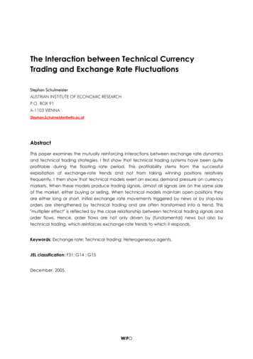
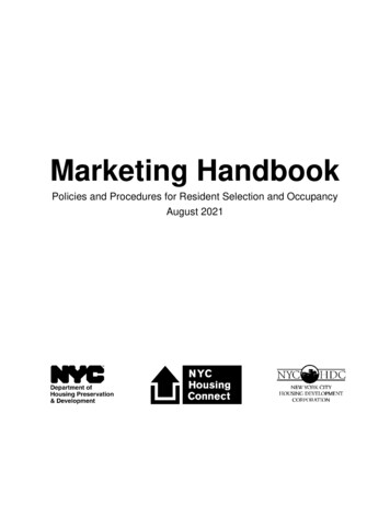
1. Basic Principles of Electricity1.7 ELECTRICAL SYSTEMS1.7.1 Medium VoltageThe most widely used medium voltage (2.4 to 35 kV) alternating current (AC) electrical distribution systems in North Americaare illustrated below:Figure 1.1 – Three phase wye(star), three wireFigure 1.2 – Three phase delta,three wireFigure 1.3 – Three phase star,four wire, grounded neutral– Three(0-2,000phase wyeFigure1.2 – Three phase delta,Typical low Figurevoltage1.1systemsV) are illustratedbelow:(star), three wirethree wire1.7.2 Low VoltageTypical(0 to2,000 V)V)areareillustratedbelow:Typicallow-voltagelow re 1.3 – Three phase star,four wire, grounded neutralFigure 1.4 – Three phase wye (star),three wire, grounded neutralFigure 1.5 – Three phase delta,four wire, grounded neutralFigure 1.4 – Three phase wye (star),three wire, grounded neutralFigure 1.5 – Three phase delta,four wire, grounded neutral3
4
2. Conductors2. CONDUCTORS2.1Strand Types72.1.1 Concentric Strand2.1.2 Bunch Strand2.1.3 Rope Strand2.1.4 Sector Conductor2.1.5 Segmental Conductor2.1.6 Annular Conductor2.1.7 Compact Strand2.1.8 Compressed Strand777778882.2Coatings102.3Tensile Strength of Copper Wire102.4Copper Strand Properties112.4.1 Strand Classes2.4.2 Solid Copper2.4.3 Class B, C and D Copper Strand2.4.4 Class H Copper2.4.5 Class I Copper2.4.6 Class K Copper2.4.7 Class M Copper11121417192021Aluminum Strand Properties222.5.1 Solid Aluminum2.5.2 Class B Aluminum2.5.3 ACSR222324Additional Conductor Properties262.6.1 Stranding, Diameter, Area and DC Resistance (32 through 4/0 AWG)2.6.2 Stranding, Diameter, Area, DC Resistanceand Weight (20 AWG through 2,000 kcmil)2.6.3 IEC Stranding262.52.628315
2. ConductorsCONDUCTORSThe conductor is the metallic component of cables through which electrical power or electrical signals are transmitted. Conductor size isusually specified by American Wire Gauge (AWG), circular mil area or in square millimeters.AWGThe American Wire Gauge (sometimes called Brown and Sharpe or B. and S.) is used almost exclusively in the USA for copper and aluminumwire. The Birmingham Wire Gauge (BWG) is used for steel armor wire.The diameters according to the AWG are defined as follows: The diameter of size 4/0 (sometimes written 0000) equals 0.4600 inch and thatof size #36 equals 0.0050 inch; the intermediate sizes are found by geometric progression. That is, the ratio of the diameter of one size tothat of the next smaller size (larger gauge number) is:390.4600 1.1229320.0050Circular MilSizes larger than 4/0 are specified in terms of the total area of a cross-section of the copper in circular mils (cmil). A circular mil is a unit of4 equal to the area of a circle one mil in diameter. It is p/4 (equal to 0.7854) of a square mil (one mil 0.001 inch). The area of a circleareain circular mils is therefore equal to the square of its diameter in mils. A solid wire one inch in diameter has an area of 1,000,000 cmils,whereas one square inch equals 4/p x 1,000,000 cmils (equal to 1,273,200 cmils). MillimetersSquare2Metric sizes are given in terms of square millimeters (mm ).Conductor CharacteristicsRelative electrical and thermal conductivities of common metal conductors are as follows:Table 2.1–Relative Electrical and Thermal Conductivities of Common Conductor MaterialsMetalSilverCopper (annealed)Copper (hard IronPlatinumTinSteelLeadRelative Electrical Conductivity at 20 C1061009772623929252318171615128Relative Thermal Conductivity at 20 C108100–7656412915241717181713-179Additional electrical properties can be found in Section 7 of this handbook.6
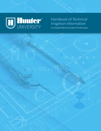
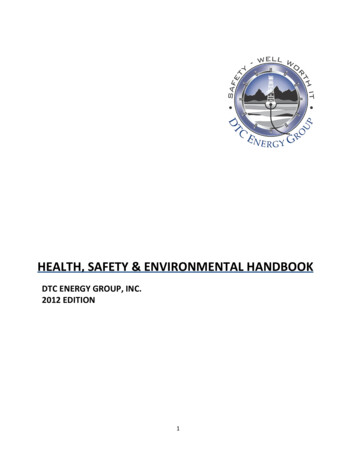
2. Conductors2.1 STRAND TYPES2.1.1 Concentric StrandA concentric stranded conductor consists of a central wire or core surrounded by one or morelayers of helically laid wires. Each layer after the first has six more wires than the precedinglayer. Except in compact stranding, each layer is usually applied in a direction opposite tothat of the layer under it.If the core is a single wire and if it and all of the outer strands have the same diameter, thefirst layer will contain six wires; the second, twelve; the third, eighteen; etc.Figure 2.1–Concentric Strand2.1.2 Bunch StrandThe term bunch stranding is applied to a collection of strands twisted together in the samedirection without regard to the geometric arrangement.Figure 2.2–Bunch Strand2.1.3 Rope StrandA rope stranded conductor is a concentric stranded conductor each of whose componentstrands is itself stranded. A rope stranded conductor is described by giving the number ofgroups laid together to form the rope and the number of wires in each group.Figure 2.3–Rope Strand2.1.4 Sector ConductorA sector conductor is a stranded conductor whose cross-section is approximately the shape ofa sector of a circle. A multiple conductor insulated cable with sector conductors has asmaller diameter than the corresponding cable with round conductors.Figure 2.4–Sector Conductor2.1.5 Segmental ConductorA segmental conductor is a round, stranded conductor composed of three or four sectorsslightly insulated from one another. This construction has the advantage of lower ACresistance due to increased surface area and skin effect.Figure 2.5–Segmental Conductor7
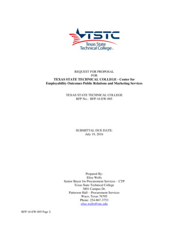
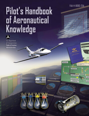
2. Conductors2.1.6 Annular ConductorAn annular conductor is a round, stranded conductor whose strands are laid around asuitable core. The core is usually made wholly or mostly of nonconducting material. Thisconstruction has the advantage of lower total AC resistance for a given cross-sectional area ofconducting material due to the skin effect.Figure 2.6–Annular Conductor2.1.7 Compact StrandA compact stranded conductor is a round or sector conductor having all layers stranded inthe same direction and rolled to a predetermined ideal shape. The finished conductor issmooth on the surface and contains practically no interstices or air spaces. This results in asmaller diameter.Figure 2.7–Compact Conductor2.1.8 Compressed StrandCompressed conductors are intermediate in size between standard concentric conductors and compact conductors. A comparison is shownbelow:SolidCompactCompressedConcentricFigure 2.8–Comparative Sizes and Shapes of 1,000 kcmil ConductorsIn a concentric stranded conductor, each individual wire is round and considerable space exists between wires. In a compressed conductor,the conductor has been put through a die that “squeezes out” some of the space between wires. In a compact conductor each wire ispreformed into a trapezoidal shape before the wires are stranded together into a finished conductor. This results in even less space betweenwires. A compact conductor is, therefore, the smallest in diameter (except for a solid conductor, of course). Diameters for common conductorsizes are given in Table 2.2.8
2. ConductorsTable 2.2–Diameters for Copper and Aluminum ConductorsConductor Size(AWG)Nominal Diameters (in.)(kcmil)SolidClass BCompactClass BCompressedClass 00001.0601.1171.152Sources: A STM B8 and B496ICEA S-95-658 (NEMA WC-70)9
2. Conductors2.2 COATINGSThere are three materials commonly used for coating a copper conductor: tin, silver and nickel.Tin is the most common and is used for improved corrosion resistance, solderability and to reduce friction between strands in flexible cables.Silver-plated conductors are used in high-temperature environments (150 C–200 C). It is also used for high-frequency applications wheresilver’s high conductivity (better than copper) and the “skin effect” work together to reduce attenuation at high frequencies.Nickel coatings are used for conductors that operate between 200 C and 450 C. At these high temperatures, copper oxidizes rapidly if notnickel plated. One drawback of nickel is its poor solderability and higher electrical resistance.2.3 TENSILE STRENGTH OF COPPER WIRETable 2.3–Tensile Strength of Copper Wire10SizeSoft or AnnealedMedium Hard DrawnHard Drawn(AWG)Max. Breaking Load (lb.)Min. Breaking Load (lb.)Min. Breaking Load 4.485.47322.012.903.53341.251.822.20360.791.161.40
2. Conductors2.4 COPPER STRAND PROPERTIES2.4.1 Strand ClassesTable 2.4–Strand ructionClassConcentric layRope lay with concentric stranded membersConstructionClassRope lay withbunch strandedmembersIUp to 2,000KBunch strandedApplicationAAFor bare conductors – usually used in overhead lines.AFor bare conductors where greater flexibility than is afforded by Class AAis required.BF or conductors insulated with various materials such as EP, XLP, PVC, etc.This is the most common class.CFor conductors where greater flexibility is required than is provided by Class B.DN/AGConductor constructions having a range of areas from 5,000,000 circularmils and employing 61 stranded members of 19 wires each down to No.14 AWG containing seven stranded members stranded members of sevenwires each. Typical uses are for portable (flexible) conductors and similarapplications.HConductor constructions having a range of areas from 5,000,000 circularmils and employing 91 stranded members of 19 wires each down to No. 9AWG containing 19 stranded members of seven wires each. Typical uses arefor rubber-jacketed cords and conductors where flexibility is required, suchas for use on take-up reels, over sheaves and apparatus conductors.Conductor SizeIndividual Wire SizeApplication(kcmil/AWG)Diameter (in.)(AWG)0.020124Typical use is for special apparatus cable.Up to 2,0000.010030Typical use is for portable cord.MUp to 1,0000.006334Typical use is for welding cable.I7, 8, 9, 100.020124Rubber-covered conductors.J10, 12, 14, 16, 18, 200.012628Fixture wire.K10, 12, 14, 16, 18, 200.010030Fixture wire, flexible cord and portablecord.L10, 12, 14, 16, 18, 200.008032Fixture wire and portable cord with greaterflexibility than Class K.M14, 16, 18, 200.006334Heater cord and light portable cord.O16, 18, 200.005036Heater cord with greater flexibility thanClass M.P16, 18, 200.004038More flexible conductors than provided inpreceding classes.Q18, 200.003140Oscillating fan cord. Very good flexibility.Source: Compiled from ASTM standards listed11
2. Conductors2.4.2 Solid CopperTable 2.5–Standard Nominal Diameters and Cross-Sectional Areas of Solid Copper WireSize(AWG)Diameter(mils)Cross-Sectional Area(kcmils)Weight(lb./1,000 ft.)Breaking StrengthSoft or Annealed 98Continued on next page 12
2. ConductorsTable 2.5–Standard Nominal Diameters and Cross-Sectional Areas of Solid Copper Wire Sectional Area(kcmils)Weight(lb./1,000 ft.)Breaking StrengthSoft or Annealed ��–461.570.00246––Source: ASTM B258, Specification for Standard Nominal Diameters and Cross-Sectional Areas of AWG Sizes of Solid Round Wires Usedas Electrical Conductors13
2. Conductors2.4.3 Class B, C and D Copper StrandTable 2.6–Class B Concentric-Lay-Stranded Copper ConductorsSizeNumber of Wires(AWG or kcmi)Diameter of Each StrandWeight(mils)(lb./1,000 ft.)Nominal Overall ntinued Table 2.6–Class B Concentric-Lay-Stranded Copper Conductors (Continued)14
2. ConductorsSizeNumber of Wires(AWG or kcmi)3/019Diameter of Each StrandWeight(mils)(lb./1,000 ft.)Nominal Overall 0712.13.1540.0363Source: ASTM B8 Specification for Concentric-Lay-Stranded Copper Conductors, Hard, Medium-Hard, or Soft15
2. ConductorsTable 2.7–Copper Strand DiametersConductor SizeStranding(AWG)(kcmil)Class B .3620.3720.3740.3741/0105.6Class BCompressed (in.)Class B Concentric Class C Concentric Class D 1.1531.153–1,100–1.1731.2091.2101.211Continued 16
2. ConductorsTable 2.7–Copper Strand Diameters (Continued)Conductor Size(AWG)Stranding(kcmil)Class B Compact(in.)Class BCompressed (in.)Class B Concentric Class C Concentric Class D 3,000–1.9381.9981.9981.9982.4.4 Class H CopperTable 2.8–Class H Rope-Lay-Stranded Copper ConductorsSize (AWG or kcmil)Number of StrandsConstructionNominal Diameter ofEach Strand (in.)Nominal O.D. (in.)Nominal Weight(lb./1,000 ed 17
2. ConductorsTable 2.8–Class H Rope-Lay-Stranded Copper Conductors (Continued)Size (AWG or kcmil)Number of StrandsConstructionNominal Diameter ofEach Strand (in.)Nominal O.D. (in.)Nominal Weight(lb./1,000 1002,0001,15961x190.04151.8686,400Source: ICEA S-95-658 (NEMA 70) Appendix K18
2. Conductors2.4.5 Class I CopperTable 2.9–Class I (24 AWG Strands) Rope-Lay-Stranded Copper ConductorsSize (AWG or 19x7x3319x7x3419x7x3619x7x37Nominal Number of 4,5224,7884,921Nominal 0.D. (in.)0.1250.1380.1560.1850.2070.2350.2630.291
If you are interested in downloading the PDF version of this book, please visit WireXpress.com. . is the flow of electric current along a conductor. This electric current takes the form of free electrons that transfer from one atom to the next. Thus, the more free electrons a material has, the better it co