Transcription
Fluid Mechanics andThermodynamics ofTurbomachinerySeventh Edition
Fluid Mechanics andThermodynamics ofTurbomachinerySeventh EditionS. L. Dixon, B. Eng., Ph.D.Honorary Senior Fellow,Department of Engineering,University of Liverpool, UKC. A. Hall, Ph.D.University Senior Lecturer in Turbomachinery,University of Cambridge, UKAMSTERDAM BOSTON HEIDELBERG LONDON NEW YORK OXFORD PARISSAN DIEGO SAN FRANCISCO SINGAPORE SYDNEY TOKYOButterworth-Heinemann is an imprint of Elsevier
Butterworth-Heinemann is an imprint of ElsevierThe Boulevard, Langford Lane, Kidlington, Oxford, OX5 1GB, UK225 Wyman Street, Waltham, MA 02451, USAFirst published by Pergamon Press Ltd. 1966Second edition 1975Third edition 1978Reprinted 1979, 1982 (twice), 1984, 1986, 1989, 1992, 1995Fourth edition 1998Fifth edition 2005 (twice)Sixth edition 2010Seventh edition 2014Copyright r 2014 S.L. Dixon and C.A. Hall. Published by Elsevier Inc. All rights reservedNo part of this publication may be reproduced or transmitted in any form or by any means, electronic or mechanical,including photocopying, recording, or any information storage and retrieval system, without permission in writing fromthe publisher. Details on how to seek permission, further information about the Publisher’s permissions policies and ourarrangements with organizations such as the Copyright Clearance Center and the Copyright Licensing Agency, can befound at our Web site: www.elsevier.com/permissionsThis book and the individual contributions contained in it are protected under copyright by the Publisher (other than asmay be noted herein).NoticesKnowledge and best practice in this field are constantly changing. As new research and experience broaden ourunderstanding, changes in research methods, professional practices, or medical treatment may become necessary.Practitioners and researchers must always rely on their own experience and knowledge in evaluating and using anyinformation, methods, compounds, or experiments described herein. In using such information or methods they should bemindful of their own safety and the safety of others, including parties for whom they have a professional responsibility.To the fullest extent of the law, neither the Publisher nor the authors, contributors, or editors, assume any liability for anyinjury and/or damage to persons or property as a matter of products liability, negligence or otherwise, or from any use oroperation of any methods, products, instructions, or ideas contained in the material herein.Library of Congress Cataloging-in-Publication DataA catalog record for this book is available from the Library of congressBritish Library Cataloguing-in-Publication DataA catalogue record for this book is available from the British LibraryISBN: 978-0-12-415954-9For information on all Butterworth-Heinemann publicationsvisit our Web site at www.elsevierdirect.comTypeset by MPS Limited, Chennai, Indiawww.adi-mps.comPrinted in the US14 15 16 17 18 10 9 8 7 6 5 4 3 2 1
DedicationIn memory of Avril (22 years) and baby Paul.
Preface to the Seventh EditionThis book was originally conceived as a text for students in their final year reading for an honorsdegree in engineering that included turbomachinery as a main subject. It was also found to be auseful support for students embarking on postgraduate courses at masters level. The book was written for engineers rather than for mathematicians, although some knowledge of mathematics willprove most useful. Also, it is assumed from the start that readers will have completed preliminarycourses in fluid mechanics. The stress is placed on the actual physics of the flows and the use ofspecialized mathematical methods is kept to a minimum.Compared to the sixth edition, this new edition has had a large number of changes made interms of presentation of ideas, new material, and additional examples. In Chapter 1, following thedefinition of a turbomachine, the fundamental laws of flow continuity, the energy and entropyequations are introduced as well as the all-important Euler work equation. In addition, the properties of working fluids other than perfect gases are covered and a steam chart is included in theappendices. In Chapter 2, the main emphasis is given to the application of the “similarity laws,” todimensional analysis of all types of turbomachine and their performance characteristics. Additionaltypes of turbomachine are considered and examples of high-speed characteristics are presented.The important ideas of specific speed and specific diameter emerge from these concepts and theirapplication is illustrated in the Cordier Diagram, which shows how to select the machine that willgive the highest efficiency for a given duty. Also, in this chapter the basics of cavitation are examined for pumps and hydraulic turbines.The measurement and understanding of cascade aerodynamics is the basis of modern axial turbomachine design and analysis. In Chapter 3, the subject of cascade aerodynamics is presented inpreparation for the following chapters on axial turbines and compressors. This chapter wascompletely reorganized in the previous edition. In this edition, further emphasis is given to compressible flow and on understanding the physics that constrain the design of turbomachine bladesand determine cascade performance. In addition, a completely new section on computational methods for cascade design and analysis has been added, which presents the details of different numerical approaches and their capabilities.Chapters 4 and 5 cover axial turbines and axial compressors, respectively. In Chapter 4, newmaterial has been added to give better coverage of steam turbines. Sections explaining the numerous sources of loss within a turbine have been added and the relationships between loss and efficiency are further detailed. The examples and end-of-chapter problems have also been updated.Within this chapter, the merits of different styles of turbine design are considered including theimplications for mechanical design such as centrifugal stress levels and cooling in high-speed andhigh temperature turbines. Through the use of some relatively simple correlations, the trends in turbine efficiency with the main turbine parameters are presented.In Chapter 5, the analysis and preliminary design of all types of axial compressors are covered.Several new figures, examples, and end-of-chapter problems have been added. There is new coverage of compressor loss sources and, in particular, shock wave losses within high-speed rotors areexplored in detail. New material on off-design operation and stage matching in multistage compressors has been added, which enables the performance of large compressors to be quantified.xi
xiiPreface to the Seventh EditionSeveral new examples and end-of-chapter problems have also been added that reflect the new material on design, off-design operation, and compressible flow analysis of high-speed compressors.Chapter 6 covers three-dimensional effects in axial turbomachinery and it possibly has the mostnew features relative to the sixth edition. There are extensive new sections on three-dimensionalflows, three-dimensional design features, and three-dimensional computational methods. The section on through-flow methods has also been reworked and updated. Numerous explanatoryfigures have been added and there are new worked examples on vortex design and additional endof-chapter problems.Radial turbomachinery remains hugely important for a vast number of applications, such as turbocharging for internal combustion engines, oil and gas transportation, and air liquefaction. As jetengine cores become more compact there is also the possibility of radial machines finding newuses within aerospace applications. The analysis and design principles for centrifugal compressorsand radial inflow turbines are covered in Chapters 7 and 8. Improvements have been made relativeto the fifth edition, including new examples, corrections to the material, and reorganization of somesections.Renewable energy topics were first added to the fourth edition of this book by way of the Wellsturbine and a new chapter on hydraulic turbines. In the fifth edition, a new chapter on wind turbineswas added. Both of these chapters have been retained in this edition as the world remains increasingly concerned with the very major issues surrounding the use of various forms of energy. Thereis continuous pressure to obtain more power from renewable energy sources and hydroelectricityand wind power have a significant role to play. In this edition, hydraulic turbines are covered inChapter 9, which includes coverage of the Wells turbine, a new section on tidal power generators,and several new example problems. Chapter 10 covers the essential fluid mechanics of wind turbines, together with numerous worked examples at various levels of difficulty. In this edition, therange of coverage of the wind itself has been increased in terms of probability theory. This allowsfor a better understanding of how much energy a given size of wind turbine can capture from a normally gusting wind. Instantaneous measurements of wind speeds made with anemometers are usedto determine average velocities and the average wind power. Important aspects concerning the criteria of blade selection and blade manufacture, control methods for regulating power output androtor speed, and performance testing are touched upon. Also included are some very brief notesconcerning public and environmental issues, which are becoming increasingly important as they,ultimately, can affect the development of wind turbines.To develop the understanding of students as they progress through the book, the expounded theories are illustrated by a selection of worked examples. As well as these examples, each chaptercontains problems for solution, some easy, some hard. See what you make of them—answers areprovided in Appendix F!
AcknowledgmentsThe authors are indebted to a large number of people in publishing, teaching, research, andmanufacturing organizations for their help and support in the preparation of this volume. In particular, thanks are given for the kind permission to use photographs and line diagrams appearing in thisedition, as listed below:ABB (Brown Boveri, Ltd.)American Wind Energy AssociationBergey Windpower CompanyDyson Ltd.Elsevier ScienceHodder EducationInstitution of Mechanical EngineersKvaener Energy, NorwayMarine Current Turbines Ltd., UKNational Aeronautics and Space Administration (NASA)NRELRolls-Royce plcThe Royal Aeronautical Society and its Aeronautical JournalSiemens (Steam Division)Sirona DentalSulzer Hydro of ZurichSussex Steam Co., UKUS Department of EnergyVoith Hydro Inc., PennsylvaniaThe Whittle Laboratory, Cambridge, UKI would like to give my belated thanks to the late Professor W.J. Kearton of the University ofLiverpool and his influential book Steam Turbine Theory and Practice, who spent a great deal oftime and effort teaching us about engineering and instilled in me an increasing and life-long interestin turbomachinery. This would not have been possible without the University of Liverpool’s awardof the W.R. Pickup Foundation Scholarship supporting me as a university student, opening doors ofopportunity that changed my life.Also, I give my most grateful thanks to Professor (now Sir) John H. Horlock for nurturing myinterest in the wealth of mysteries concerning the flows through compressors and turbine bladesduring his tenure of the Harrison Chair of Mechanical Engineering at the University of Liverpool.At an early stage of the sixth edition some deep and helpful discussions of possible additions to thenew edition took place with Emeritus Professor John P. Gostelow (a former undergraduate studentof mine). There are also many members of staff in the Department of Mechanical Engineering during my career who helped and instructed me for which I am grateful.Also, I am most grateful for the help given to me by the staff of the Harold Cohen Library,University of Liverpool, in my frequent searches for new material needed for the seventh edition.xiii
xivAcknowledgmentsLast, but by no means least, to my wife Rosaleen, whose patient support and occasional suggestions enabled me to find the energy to complete this new edition.S. Larry DixonI would like to thank the University of Cambridge, Department of Engineering, where I havebeen a student, researcher, and now lecturer. Many people there have contributed to my development as an academic and engineer. Of particular importance is Professor John Young who initiatedmy enthusiasm for thermofluids through his excellent teaching of the subject. I am also very grateful to Rolls-Royce plc, where I worked for several years. I learned a huge amount about compressorand turbine aerodynamics from my colleagues there and they continue to support me in myresearch activities.Almost all the contributions I made to this new edition were written in my office at King’sCollege, Cambridge, during a sabbatical. As well as providing accommodation and food, King’s isfull of exceptional and friendly people who I would like to thank for their companionship and helpduring the preparation of this book.As a lecturer in turbomachinery, there is no better place to be based than the WhittleLaboratory. I would like to thank the members of the laboratory, past and present, for their supportand all they have taught me. I would like to make a special mention of Dr. Tom Hynes, my Ph.D.supervisor, for encouraging my return to academia from industry and for handing over the teachingof a turbomachinery course to me when I started as a lecturer. During my time in the laboratory,Dr. Rob Miller has been a great friend and colleague and I would like to thank him for the soundadvice he has given on many technical, professional, and personal matters. Several laboratory members have also helped in the preparation of suitable figures for this book. These include Dr. GrahamPullan, Dr. Liping Xu, Dr Martin Goodhand, Vicente Jerez-Fidalgo, Ewan Gunn, and PeterO’Brien.Finally, special personal thanks go to my parents, Hazel and Alan, for all they have done forme. I would like to dedicate my work on this book to my wife Gisella and my son Sebastian.Cesare A. Hall
List of SymbolsAaa; a0bCc, CfCL, CDCFCpCvCX, CYccodDDhDsDFE, eFFcfgHHEHfHGHShIiJjK, kLlMmNnoPareasonic velocityaxial-flow induction factor, tangential flow induction factoraxial chord length, passage width, maximum camberchordwise and tangential force coefficientslift and drag coefficientscapacity factor ð 5 PW PR Þspecific heat at constant pressure, pressure coefficient, pressure rise coefficientspecific heat at constant volumeaxial and tangential force coefficientsabsolute velocityspouting velocityinternal diameter of pipedrag force, diameterhydraulic mean diameterspecific diameterdiffusion factorenergy, specific energyforce, Prandtl correction factorcentrifugal force in bladefriction factor, frequency, accelerationgravitational accelerationblade height, headeffective headhead loss due to frictiongross headnet positive suction head (NPSH)specific enthalpyrothalpyincidence anglewind turbine tip speed ratiowind turbine local blade-speed ratioconstantslift force, length of diffuser wallblade chord length, pipe lengthMach numbermass, molecular massrotational speed, axial length of diffusernumber of stages, polytropic indexthroat widthpowerxv
xviPRPWppapvqQRReRHRorSsTtUuV, vWΔWWxwXx, yx, y, zYYpZαβΓγδεζηθκλμνξρList of Symbolsrated power of wind turbineaverage wind turbine powerpressureatmospheric pressurevapor pressurequality of steamheat transfer, volume flow ratereaction, specific gas constant, diffuser radius, stream tube radiusReynolds numberreheat factoruniversal gas constantradiusentropy, power ratioblade pitch, specific entropytemperaturetime, thicknessblade speed, internal energyspecific internal energyvolume, specific volumework transfer, diffuser widthspecific work transfershaft workrelative velocityaxial forcedryness fraction, wetness fractionCartesian coordinate directionstangential forcestagnation pressure loss coefficientnumber of blades, Zweifel blade loading coefficientabsolute flow anglerelative flow angle, pitch angle of bladecirculationratio of specific heatsdeviation anglefluid deflection angle, cooling effectiveness, drag lift ratio in wind turbinesenthalpy loss coefficient, incompressible stagnation pressure loss coefficientefficiencyblade camber angle, wake momentum thickness, diffuser half angleangle subtended by log spiral vaneprofile loss coefficient, blade loading coefficient, incidence factordynamic viscositykinematic viscosity, hub tip ratio, velocity ratioblade stagger angledensity
List of SymbolsσσbσcτφψΩΩSΩSPΩSSωslip factor, solidity, Thoma coefficientblade cavitation coefficientcentrifugal stresstorqueflow coefficient, velocity ratio, wind turbine impingement anglestage loading coefficientspeed of rotationspecific speedpower specific speedsuction specific Rrrefrelsssttsttstagnation propertybladecompressor, centrifugal, criticalcritical valuedesigndiffuserexithydraulic, hubinlet, impelleridealmean, meridional, mechanical, materialmaximumminimumnozzlenormal componentoveralloptimumpolytropic, pump, constant pressurereversible process, rotorradialreference valuerelativeisentropic, shroud, stall conditionstage isentropicturbine, tip, transversetotal-to-statictotal-to-totalxvii
xviiivx, y, zθList of SymbolsvelocityCartesian coordinate componentstangentialSuperscripts.0 time rate of changeaverageblade angle (as distinct from flow angle)nominal condition, throat conditionnondimensionalized quantity
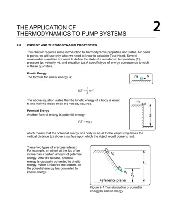
CHAPTERIntroduction: Basic Principles1Take your choice of those that can best aid your action.Shakespeare, Coriolanus1.1 Definition of a turbomachineWe classify as turbomachines all those devices in which energy is transferred either to, or from, a continuously flowing fluid by the dynamic action of one or more moving blade rows. The word turbo orturbinis is of Latin origin and implies that which spins or whirls around. Essentially, a rotating bladerow, a rotor or an impeller changes the stagnation enthalpy of the fluid moving through it by doingeither positive or negative work, depending upon the effect required of the machine. These enthalpychanges are intimately linked with the pressure changes occurring simultaneously in the fluid.Two main categories of turbomachine are identified: first, those that absorb power to increasethe fluid pressure or head (ducted and unducted fans, compressors, and pumps); second, those thatproduce power by expanding fluid to a lower pressure or head (wind, hydraulic, steam, and gas turbines). Figure 1.1 shows, in a simple diagrammatic form, a selection of the many varieties of turbomachines encountered in practice. The reason that so many different types of either pump(compressor) or turbine are in use is because of the almost infinite range of service requirements.Generally speaking, for a given set of operating requirements one type of pump or turbine is bestsuited to provide optimum conditions of operation.Turbomachines are further categorized according to the nature of the flow path through the passages of the rotor. When the path of the through-flow is wholly or mainly parallel to the axis ofrotation, the device is termed an axial flow turbomachine (e.g., Figures 1.1(a) and (e)). When thepath of the through-flow is wholly or mainly in a plane perpendicular to the rotation axis, thedevice is termed a radial flow turbomachine (e.g., Figure 1.1(c)). More detailed sketches of radialflow machines are given in Figures 7.3, 7.4, 8.2, and 8.3. Mixed flow turbomachines are widelyused. The term mixed flow in this context refers to the direction of the through-flow at the rotoroutlet when both radial and axial velocity components are present in significant amounts.Figure 1.1(b) shows a mixed flow pump and Figure 1.1(d) a mixed flow hydraulic turbine.One further category should be mentioned. All turbomachines can be classified as either impulseor reaction machines according to whether pressure changes are absent or present, respectively, inthe flow through the rotor. In an impulse machine all the pressure change takes place in one ormore nozzles, the fluid being directed onto the rotor. The Pelton wheel, Figure 1.1(f), is an exampleof an impulse turbine.Fluid Mechanics and Thermodynamics of Turbomachinery. DOI: -2Copyright 2014 S.L. Dixon and C.A. Hall. Published by Elsevier Inc. All rights reserved.1
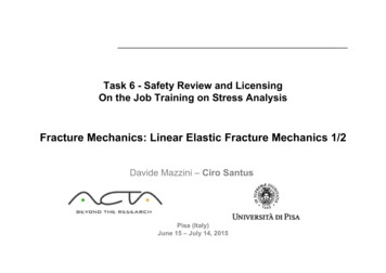
2CHAPTER 1 Introduction: Basic PrinciplesRotor bladesRotor bladesOutlet vanesFlowOutlet vanesFlow(a)(b)Flow directionGuide vanesRunner bladesOutlet diffuserVaneless diffuserVoluteFlowFlowDraught tubeImpeller(c)(d)Guide vanesNozzleFlowFlowWheelInlet pipeFlowDraught tubeor diffuserJet(e)(f)FIGURE 1.1Examples of turbomachines. (a) Single stage axial flow compressor or pump, (b) mixed flow pump, (c) centrifugalcompressor or pump, (d) Francis turbine (mixed flow type), (e) Kaplan turbine, and (f) Pelton wheel.The main purpose of this book is to examine, through the laws of fluid mechanics and thermodynamics, the means by which the energy transfer is achieved in the chief types of turbomachines,together with the differing behavior of individual types in operation. Methods of analyzing the flowprocesses differ depending upon the geometrical configuration of the machine, whether the fluidcan be regarded as incompressible or not, and whether the machine absorbs or produces work. Asfar as possible, a unified treatment is adopted so that machines having similar configurations andfunction are considered together.1.2 Coordinate systemTurbomachines consist of rotating and stationary blades arranged around a common axis, whichmeans that they tend to have some form of cylindrical shape. It is therefore natural to use a
1.2 Coordinate system3CasingcmcrFlow streamsurfacescxBladeHubrxAxis of rotation(a)rrθCasingmcθcmβU ΩrrθwθαwcθHubΩUc(b)(c)FIGURE 1.2The coordinate system and flow velocities within a turbomachine. (a) Meridional or side view, (b) view alongthe axis, and (c) view looking down onto a stream surface.cylindrical polar coordinate system aligned with the axis of rotation for their description and analysis. This coordinate system is pictured in Figure 1.2. The three axes are referred to as axial x, radialr, and tangential (or circumferential) rθ.In general, the flow in a turbomachine has components of velocity along all three axes, whichvary in all directions. However, to simplify the analysis it is usually assumed that the flow does notvary in the tangential direction. In this case, the flow moves through the machine on axi-symmetricstream surfaces, as drawn on Figure 1.2(a). The component of velocity along an axi-symmetricstream surface is called the meridional ��(1.1)cm 5 c2x 1 c2r
4CHAPTER 1 Introduction: Basic PrinciplesIn purely axial flow machines the radius of the flow path is constant and, therefore, referring toFigure 1.2(c) the radial flow velocity will be zero and cm 5 cx. Similarly, in purely radial flowmachines the axial flow velocity will be zero and cm 5 cr. Examples of both of these types ofmachines can be found in Figure 1.1.The total flow velocity is made up of the meridional and tangential components and can ��ffiffiffiffiffiffiffiffiffiffi qffiffiffiffiffiffiffiffiffiffiffiffiffiffiffic 5 c2x 1 c2r 1 c2θ 5 c2m 1 c2θ(1.2)The swirl, or tangential, angle is the angle between the flow direction and the meridionaldirection:α 5 tan21 ðcθ cm Þ(1.3)Relative velocitiesThe analysis of the flow-field within the rotating blades of a turbomachine is performed in a frameof reference that is stationary relative to the blades. In this frame of reference the flow appears assteady, whereas in the absolute frame of reference it would be unsteady. This makes any calculations significantly easier, and therefore the use of relative velocities and relative flow quantities isfundamental to the study of turbomachinery.The relative velocity w is the vector subtraction of the local velocity of the blade U from theabsolute velocity of the flow c, as shown in Figure 1.2(c). The blade has velocity only in the tangential direction, and therefore the components of the relative velocity can be written aswθ 5 cθ 2 U; wx 5 cx ; wr 5 cr(1.4)The relative flow angle is the angle between the relative flow direction and the meridionaldirection:β 5 tan21 ðwθ cm Þ(1.5)By combining Eqs. (1.3), (1.4), and (1.5) a relationship between the relative and absolute flowangles can be found:tan β 5 tan α 2 U cm(1.6)Sign conventionEquations (1.4) and (1.6) suggest that negative values of flow angles and velocities are possible. Inmany turbomachinery courses and texts, the convention is to use positive values for tangentialvelocities that are in the direction of rotation (as they are in Figure 1.2(b) and (c)), and negativevalues for tangential velocities that are opposite to the direction of rotation. The conventionadopted in this book is to ensure that the correct vector relationship between the relative and absolute velocities is applied using only positive values for flow velocities and flow angles.
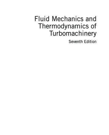
1.2 Coordinate system5Velocity diagrams for an axial flow compressor stageA typical stage of an axial flow compressor is shown schematically in Figure 1.3 (looking radiallyinwards) to show the arrangement of the blading and the flow onto the blades.The flow enters the stage at an angle α1 with a velocity c1. This inlet velocity is set by whateveris directly upstream of the compressor stage: an inlet duct, another compressor stage or an inletguide vane (IGV). By vector subtraction the relative velocity entering the rotor will have a magnitude w1 at a relative flow angle β 1 . The rotor blades are designed to smoothly accept this relativeflow and change its direction so that at outlet the flow leaves the rotor with a relative velocity w2at a relative flow angle β 2 . As shown later in this chapter, work will be done by the rotor blades onthe gas during this process and, as a consequence, the gas stagnation pressure and stagnation temperature will be increased.By vector addition the absolute velocity at rotor exit c2 is found at flow angle α2 . This flowshould smoothly enter the stator row which it then leaves at a reduced velocity c3 at an absoluteangle α3 . The diffusion in velocity from c2 to c3 causes the pressure and temperature to rise further.Following this the gas is directed to the following rotor and the process goes on repeating throughthe remaining stages of the compressor.The purpose of this brief explanation is to introduce the reader to the basic fluid mechanicalprocesses of turbomachinery via an axial flow compressor. It is hoped that the reader will followthe description given in relation to the velocity changes shown in Figure 1.3 as this is fundamentalto understanding the subject of turbomachinery. Velocity triangles will be considered in furtherdetail for each category of turbomachine in later GURE 1.3Velocity triangles for an axial compressor stage.
6CHAPTER 1 Introduction: Basic PrinciplesEXAMPLE 1.1The axial velocity through an axial flow fan is constant and equal to 30 m/s. With the notationgiven in Figure 1.3, the flow angles for the stage are α1 and β 2 are 23 and β 1 and α2 are 60 .From this information determine the blade speed U and, if the mean radius of the fan is0.15 m, find the rotational speed of the rotor.SolutionThe velocity components are easily calculated as follows:wθ1 5 cx tan β 1andcθ1 5 cx tan α1‘Um 5 cθ1 1 wθ1 5 cx ðtan α1 1 tan β 1 Þ 5 64:7 m sThe speed of rotation isΩ5Um5 431:3 rad s or 431:3 3 30 π 5 4119 rpmrm1.3 The fundamental lawsThe remainder of this chapter summarizes the basic physical laws of fluid mechanics and thermodynamics, developing them into a form suitable for the study of turbomachines. Following this, theproperties of fluids, compressible flow relations and the efficiency of compression and expansionflow processes are covered.The laws discussed arei.ii.iii.iv.thethethethecontinuity of flow equation;first law of thermodynamics and the steady flow energy equation;momentum equation;second law of thermodynamics.All of these laws are usually covered in first-year university engineering and technologycourses, so only the briefest discussion and analysis is given here. Some textbooks dealing comprehensively with these laws are those written by Çengel and Boles (1994), Douglas, Gasiorek andSwaffield (1995), Rogers and Mayhew (1992), and Reynolds and Perkins (1977). It is worthremembering that these laws are completely general; they are independent of the nature of the fluidor whether the fluid is compressible or incompressible.1.4 The equation of continuityConsider the flow of a fluid with density ρ, through the element of area dA, during the time intervaldt. Referring to Figure 1.4, if c is the stream velocity the elementary mass is dm 5 ρcdtdA cosθ,where θ is the angle subtended by the normal of the area element to the stream direction.
1.5 The first law of thermodynamics7Stream linescdAndA θc · dtFIGURE 1.4Flow across an element of area.The element of area perpendicular to the flow direction is dAn 5 dA cosθ and so dm 5 ρcdAndt. Theelementary rate of mass flow is thereforedm 5dm5 ρcdAndt(1.7)Most analyses in this book are limited to one-dimensional steady flows where the velocity anddensity are regarded as constant across each section of a duct or passage. If An1 and An2 are theareas normal to the flow direction at stations 1 and 2 along a passage respectively, thenm 5 ρ1 c1 An1 5 ρ2 c2 An2 5 ρcAn(1.8)since there is no accumulation of fluid within the control volume.1.5 The first law of thermodynamicsThe first law of thermodynamics states that, if
courses in fluid mechanics. The stress is placed on the actual physics of the flows and the use of specialized mathematical methods is kept to a minimum. Compared to the sixth edition, this new edition has had a large number of changes made in terms of presentation of ideas, new mater