Transcription
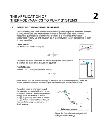
THE APPLICATION OFTHERMODYNAMICS TO PUMP SYSTEMS2.0ENERGY AND THERMODYNAMIC PROPERTIESThis chapter requires some introduction to thermodynamic properties and states. No needto panic, we will use only what we need to know to calculate Total Head. Severalmeasurable quantities are used to define the state of a substance: temperature (T),pressure (p), velocity (v), and elevation (z). A specific type of energy corresponds to eachof these quantities.Kinetic EnergyThe formula for kinetic energy is:KE 1 2mv2The above equation states that the kinetic energy of a body is equalto one half the mass times the velocity squared.Potential EnergyAnother form of energy is potential energy:PE mg zwhich means that the potential energy of a body is equal to the weight (mg) times thevertical distance (z) above a surface upon which the object would come to rest.These two types of energies interact.For example, an object at the top of anincline has a certain amount of potentialenergy. After it's release, potentialenergy is gradually converted to kineticenergy. When it reaches the bottom, allthe potential energy has converted tokinetic energy.Figure 2-1 Transformation of potentialenergy to kinetic energy.
2 2THE APPLICATION OF THERMODYNAMICS TO PUMP SYSTEMSThe principle of conservation of energy states that energy can neither be created or lost.Consequently, if one form of energy decreases then another form must increase. Thisallows us to make an energy balance that describes the energy variation of the object inFigure 2-1. KE PE 0[2-1]In other words, equation [2-1] reads: the sum of the potential and kinetic energy variationbetween points 1 and 2 is equal to zero.Energy levels are associated with positions within a system, position 1 is the top of theslope and position 2 the bottom. PE PE 1 PE 2 and KE K E 1 KE 2mg ( z 1 z 2 ) 1m( v1 2 v 2 2 ) 02v 2 2 v1 2 2 g ( z1 z 2 )[2-2]Equation [2-1] expresses the principle of conservation of energy for this system. Thisleads to equation [2-2] that describes how velocity changes with respect to height. Theprinciple of conservation of energy makes it possible to account for all forms of energy ina system. The energies present in the system are in continuous change and the termdelta ( ) is used in equation [2-1] to indicate a change or variation in energy.Thermodynamic propertiesThermodynamic properties are the different types of energies associated with a body (forexample, potential, kinetic, internal or external). It is characteristic of a thermodynamicproperty is that its value is independent of the method or path taken to get from one valueto another or from an initial state 1 to another state 2. The potential energy (PE) and thekinetic energy (KE) are thermodynamic properties. We require other energy quantities(work and heat) to account for real world conditions. These quantities are dependent onthe path or method used to get from state 1 to state 2 (more about paths later).2.1CLOSED SYSTEMS AND INTERNAL ENERGYThe system shown in Figure 2-2 is a fluid contained in a sealed tube with its inletconnected to its outlet forming a closed system.
THE APPLICATION OF THERMODYNAMICS TO PUMP SYSTEMS2 3Internal EnergyAll fluids have internal energy (U). If we apply a heat source to the system, thetemperature, pressure and internal energy of the fluid will increase. Internal energy is theenergy present at the molecular level of the substance.Figure 2-2 The relationship between internalenergy and heat gain within a closed system.Closed SystemsIn a closed system no mass enters or leaves the boundary. What happens if we put a fluidwithin a closed environment such as a sealed container and apply heat? Pressure andtemperature in the fluid will increase. The temperature rise indicates that the internalenergy of the fluid has increased.The heat source increases the internal energy of the fluid from U1 to U2 . The energyquantities present in this system are the internal energy (U) and the heat loss (Q).Therefore, the energy balance is:Q QC QE U U 1 U 2QC is the quantity of heat absorbed by the fluid from the source and QE is the heat loss ofthe fluid to the environment. The internal energy has changed from its level at instant 1 toanother level at instant 2 (after heat is applied). The internal energy (U) is athermodynamic property.2.2CLOSED SYSTEMS, INTERNAL ENERGY AND WORKAnother way to increase the internal energy of a fluid is to do work on it by means of apump. In this way, without applyingheat, the work done on the fluidthrough the pump raises the internalenergy of the fluid from U1 to U2. Thiscauses the temperature of the fluid toincrease, producing a heat loss QE tothe environment.Figure 2-3 The relationship between internalenergy, work and heat loss within a closedsystem.
2 4THE APPLICATION OF THERMODYNAMICS TO PUMP SYSTEMSIn this situation, the energy balance is:QE W U U 1 U 2The sign convention is positive energy for heat leaving the system and negative energyfor heat or work entering the system.2.3OPEN SYSTEMS AND ENTHALPYFigure 2-4 The relationship between internal energy, heat loss, work, and apressurized environment for an open system.An open system is one where mass is allowed to enter and exit. The mass entering thesystem displaces an equal amount of mass that exits. A clearly defined boundary, calledthe control volume, envelops the system and intersects the inlet and outlet. The controlvolume allows us to apply the principle of conservation of energy. Each unit of mass (m1)and volume (V1) that enters the system is subject to a pressure (p1) at the inlet. The sameis true of the mass leaving the system (m2) of volume (V2) and subjected to a pressure (p2).The principle of conservation of mass requires that m1 m2. In this book, we are dealingonly with incompressible fluids where V1 V2. The pressure at the inlet produces a certainquantity of work that helps push the fluid through the system. The pressure at the outletproduces work opposing that movement. The difference between these two workcomponents is the work associated with pressure at the inlet and outlet of the system.This difference is the energy term (pV) and is the only difference between the systemsshown in Figure 2-3 vs. the system shown in Figure 2-4.
THE APPLICATION OF THERMODYNAMICS TO PUMP SYSTEMS2 5The energy balance is:Q E W U ( pV ) En U and (pV) are terms that always occur together in an open system. For that reasontheir sum has been given the name enthalpy (En). Enthalpy is also a thermodynamicproperty.2.4OPEN SYSTEMS, ENTHALPY, KINETIC AND POTENTIAL ENERGYIn closed systems, the fluid particles move from one end of the container to another butthey do not leave the container. It is impossible to have a net effect on the velocity andtherefore on the kinetic energy of the system. In open systems, fluid particles move fromthe inlet to the outlet and leave the system. If the velocity varies between inlet and outlet,the kinetic energy varies. The pump is the energy source that compensates for thevariation.The same is true for potential energy in a closed system. A fluid particle that goes fromthe bottom of a container to the top will eventually return to the bottom. There can be nonet effect on the potential energy of this system. In an open system, fluid particles canleave the system at a different elevation than they enter producing a variation in potentialenergy. The pump also compensates for this energy variation.Potential EnergyThe difference in vertical position at which the fluid enters and leaves the system causesthe potential energy of a fluid particle to increase or decrease. The potential energyincreases when the fluid leaves at a higher elevation than it enters. The pump providesenergy to compensate for the increase in potential energy. If the fluid leaves the system ata lower elevation than it enters, the potential energy decreases and it is possible toconvert this energy to useful work. This is what happens in a hydroelectric dam. Achannel behind the dam wall brings water to a turbine located beneath the dam structure.The flow of water under pressure turns a turbine that is coupled to a generator producingelectricity. The difference in elevation or potential energy of the fluid is the source ofenergy for the generator.Kinetic EnergyThere is often a velocity difference between the inlet and outlet of a system. Usually thevelocity is higher at the outlet versus the inlet; this produces an increase in kinetic energy.The pump compensates for this difference in kinetic energy levels.The complete energy balance for an open system is:Q E W En KE PE[2-3]
2 6THE APPLICATION OF THERMODYNAMICS TO PUMP SYSTEMSEquation [2-3] has the thermodynamic properties on the right-hand side. The heat loss(QE) and the work done on the system (W), which are not thermodynamic properties, areon the left-hand side of the equation. To determine QE and W, it is necessary to know howthe heat is produced (i.e. path that the fluid must take between inlet and outlet) and howthe work is done.2.5WORK DONE BY THE PUMPThe role of a pump is toprovide sufficient pressure tomove fluid trough the systemat the required flow rate. Thisenergy compensates for theenergy losses due to friction,elevation, velocity andpressure differences betweenthe inlet and outlet of thesystem. This book does notdeal with the method by whicha pump can pressurize a fluidwithin its casing. The readeris referred to reference 15, avery detailed treatment of thissubject. For our purpose, theFigure 2-5 The work provided by the pump.pump is a black box whosefunction is to increase the fluid pressure at a given flow rate.2.6FLUID AND EQUIPMENT FRICTION LOSSThe total heat loss (QE) is the sum of fluid friction loss and equipment friction loss.Q E Q F Q EQFluid Friction Loss (QF)How is it possible to go from anebulous concept such as fluid frictionto the pressure drop due to friction?Friction occurs within the fluid andbetween the fluid and the walls. Adetailed method of fluid frictioncalculation is presented in Chapter 3.Friction in fluids produces heat (QF )which dissipates to the environment.The temperature increase isnegligible. If we can estimate thefriction force, we know that we mustsupply an equal and opposite force toovercome it.Figure 2-6 Heat loss due to fluid friction withinpipes.
THE APPLICATION OF THERMODYNAMICS TO PUMP SYSTEMS2 7The energy corresponding to the heat loss (QF) must be supplied by the pump. The netforce (FF) required to balance the friction force is F1-F2 These forces are the result of theaction of pressures p1 and p2 (see Figure 2-6). The difference between p1 and p2 is thepressure differential or pressure drop due to friction for a given length of pipe. Manypublications (reference 1 and 8 for example) provide pressure head drop values in theform of tables. The pressure head drop can also be calculated by the Colebrook equation,which we will discuss in chapter 3.Equipment Friction Loss (QEQ)Many different types of equipment are present in typical industrial systems. Controlvalves, filters, etc., are examples of equipment that have an effect on the fluid. Because ofthe great variety of different equipment that can be installed, it is not possible to analyzeeveryone of them. However we can quantify the effect of the equipment by determiningthe pressure drop across the equipment much as we did with the pressure drop acrossthe pump. Again it is not necessary to know exactly what happens inside the equipment tobe able estimate this effect. Pressure drop (difference between inlet and outlet pressure)is the outward manifestation of the effect of equipment. This pressure drop produces heat(QEQ) which is then lost through the fluid to the environment. The heat loss is calculated inthe same manner as the pump work (W).Q EQ p EQmρThe product supplier normally makes available the amount of pressure drop for theequipment at various flow rates in the form of charts or tables.2.7THE CONTROL VOLUMEUp to now we have been using control volumes without defining their purpose. A controlvolume is an imaginary boundary that surrounds a system and intersects all inlets andoutlets. This makes it possible to apply the principle of conservation of mass. Theboundary of the system is determined by appropriately locating the inlet and the outlet.The term “appropriate” refers to locating the boundary at points where the conditions(pressure, elevation and velocity) are known. The control volume encompasses allinternal and external the energy sources affecting the system. This makes it possible toapply the principle of conservation of energy.How is the control volume positioned in real systems? Figure 2-7 shows a typicalindustrial process. Suppose that we locate the inlet (point 1) on the inlet pipe as shown inFigure 2-7. Is this reasonable? Where exactly should we locate it, will any position due?Clearly no. Point l could be located anywhere on the feed line to the suction tank. Theproblem with locating point 1 on the inlet line is precisely that the location isindeterminate.
2 8.THE APPLICATION OF THERMODYNAMICS TO PUMP SYSTEMSFigure 2-7 Incorrect positioning of the control volumein a pumping system.However, consider Figure 2-8. The pressure head at the inlet of the pump is proportionalto the elevation of the suction tank fluid surface. We locate the inlet of the system (point 1)on the suction tank fluid surface since any change in the elevation of point 1 will affect thepump. The inlet pipe is the means by which we supply the pump with enough fluid tooperate. As far as this system is concerned, the inlet feed pipe is irrelevant. This isbecause the pressure head at the inlet of the pump (or any point within the system) isdependent on the level of the suction fluid tank surface. The other reason that requires usto locate point 1 on the liquid surface of the suction tank is that the control vo
heat, the work done on the fluid through the pump raises the internal energy of the fluid from U 1 to U 2. This causes the temperature of the fluid to increase, producing a heat loss Q E to the environment. Figure 2-2 The relationship between internal energy and heat gain within a closed system. Figure 2-3 The relationship between internalFile Size: 1MBPage Count: 34