Transcription
Technical white paperCheck if the document is availablein the language of your choice.HPE NIMBLE STORAGEPEER PERSISTENCEDeployment considerations for NimbleOS 5.1 and later
Technical white paperCONTENTSExecutive summary. 3Synchronous replication on HPE Nimble Storage arrays . 3Array groups . 4Volume collections . 5Other Peer Persistence components . 5Witness. 5Automatic failover . 5Automatic switchover . 5Infrastructure requirements . 6Supported HPE Nimble Storage arrays . 6Supported operating systems. 7NimbleOS 5.1.x features . 7Multi-protocol access to an array . 7Group scoped target iSCSI volumes . 7Support for synchronous replication . 7Network requirements and considerations . 9Installation and setup procedures .10Installing and configuring the Witness.10Configuring the host .20Setting up the Initial array configuration .20Adding the second array .23Setting up ASO .26Important CLI steps .27Configuring synchronously replicated volumes .28Validating synchronous replication setup.38Automatic or manual switchover .40Manual failover/switchover when the GL fails .40Manual failover/switchover when the BGL fails.49Advantages of using ASO versus manual handover.57Restoring active paths for volumes after recovering from an ASO.57Conditions that block ASO .57Unavailable Witness .57Local controller failover .58Volume collection out of sync .58Testing Peer Persistence functionality .59Test Witness failure or disconnect .59Test failure or failover of the array’s local controller .63Test failure of a single replication link .65Test failure of all replication links .67Test array failure .70
Technical white paperUpgrading the Witness .78Upgrade current Witness server.78Replace current Witness server VM with new server VM from the updated Witness OVA package.78Changing network settings for Witness VM deployed through OVA package .80Detailed cabling diagram .81Checklist .82Summary .82
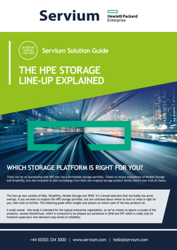
Technical white paperPage 3EXECUTIVE SUMMARYThe HPE Nimble Storage Peer Persistence feature is designed for applications that require zero to near-zero recovery point objectives(RPO) and recovery time objectives (RTO). By using multi-site synchronous replication with automatic switchover (ASO), Peer Persistenceenables business continuity, keeping your applications online all of the time. This white paper explains basic concepts of Peer Persistenceand describes networking requirements and recommendations. It also shows how to deploy host toolkits and quorum witness software toautomate switchover to synchronously replicated volumes and how to configure HPE Nimble Storage arrays to create and accesssynchronously replicated volumes.Target audience: The target audience for this paper includes storage administrators and systems integrators who are planning to deployHPE Nimble Storage Peer Persistence in their data centers.Document purpose: This document describes the building blocks and basic configuration required to deploy Peer Persistence withHPE Nimble Storage arrays and explains some of the methodology that is needed to test the ASO functionality. For more information,including detailed administration guides, see the documentation page on the HPE InfoSight portal.SYNCHRONOUS REPLICATION ON HPE NIMBLE STORAGE ARRAYSSynchronous replication is a business continuity solution that uses LAN or WAN technologies to mirror data between sites, ensuring theexistence of multiple copies of guaranteed up-to-date information. Synchronous replication provides protection from array, environment, orsite failures with no data loss because all I/O is mirrored across sites with a true RPO of zero—an achievement that is neither available norpossible with periodic snapshot-based replication. To understand how to deploy Peer Persistence with HPE Nimble Storage arrays, it helpsto have an understanding of how synchronous replication has been implemented in NimbleOS 5.1.x.All HPE Nimble Storage arrays have two controllers, one active and one standby. As Figure 1 shows, when an initiator writes data to avolume on the array, the data lands in non-volatile random access memory (NVRAM) on the active controller and is immediately replicatedacross a chassis backplane to the NVRAM in the standby controller. The array waits until the data is successfully mirrored to the NVRAM inthe standby controller before it acknowledges to the initiator that the data has been written.FIGURE 1. Flow of data during write operation to HPE Nimble Storage array (cabling omitted for standby controller)
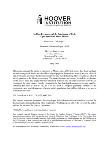
Technical white paperPage 4For synchronous replication, HPE Nimble Storage arrays extend the number of copies of data that are written before the write operation isacknowledged to the initiator. If an initiator writes data to a volume that is configured for synchronous replication, the data lands in theNVRAM of the active controller on the array that is presenting the volume to the initiator. Next, the data is mirrored across the chassisbackplane to the standby controller in the same array, and then it is copied across an IP address interface to the active controller in thesecond HPE Nimble Storage array. Finally, the data is mirrored across the second array’s backplane into the NVRAM on the second array’sstandby controller. Only after the data is successfully copied to all of these locations does the first array acknowledge to the initiator that thedata has been written. Figure 2 shows the data paths that are used for synchronous replication.FIGURE 2. Data paths for synchronous replication (cabling omitted for standby controllers)Array groupsEvery HPE Nimble Storage array belongs to an array group, even if the group consists of a single array. As more arrays are added to thegroup, the first array becomes the group leader (GL), and all of the arrays are managed as a single entity through the GL’s managementIP address. The GL maintains all configuration data for all arrays in the group.Beginning with NimbleOS 5.1.x, the role of backup group leader (BGL) has been defined. This role can be assigned to one of the arrays inthe group. All of the group configuration data is mirrored between the GL and the BGL, and it is easy in NimbleOS 5.1.x to migrate the GLrole to the BGL array.Because of the new BGL role, it is important to include a secondary management IP address in the array group’s network configuration.The secondary management IP address can be used to open an SSH session with the BGL array, but it cannot provide GUI access to thearray group or the BGL. If the BGL array assumes the role of GL, it becomes inaccessible through the secondary management IP address. Assoon as an array is designated as the GL, access to that array shifts to the primary management IP address. The secondary management IPaddress can be used to access the new BGL array through the CLI—if and when it comes online.In general, an HPE Nimble Storage array group can consist of up to four arrays, but for synchronous replication configurations the maximum(and minimum) group size is two arrays. When multiple arrays are configured in the same array group, NimbleOS makes it possible for each
Technical white paperPage 5array to have a separate storage pool or for storage pools to include multiple arrays. In a synchronous replication configuration, however, allarrays in the array group must be in separate storage pools.Volume collectionsIn NimbleOS, volume collections are groups of volumes that have the same data protection requirements (such as snapshot consistency,frequency, and retention) and the same replication rules. Volumes are designated for synchronous replication at the volume collection level.A volume collection can be set up to synchronously replicate all of the volumes it contains to the partner pool in the array group.All volume
HPE Nimble Storage automatic failover (AFO) is the failing over of the group management services from the GL to the BGL . This action occurs as a precursor to a Peer Persistence ASO if the GL array becomes