Transcription
ELISE MOSSAutodeskAutodesk Certified Instructor AutoCAD 2019Fundamentals SDCP U B L I C AT I O N SBetter Textbooks. Lower Prices.www.SDCpublications.com
Visit the following websites to learn more about this book:Powered by TCPDF (www.tcpdf.org)
Lesson 3.0 – Drawing LinesEstimated Class Time: 2 HoursObjectivesThis section introduces AutoCAD commands for creating a simple drawing. Starting with a New drawing,the user will learn to draw lines using different methods. Start From ScratchUse the New command to begin a new drawing from “scratch.” LineDraw line segmentsUsing Direct Distance MethodUsing Polar TrackingUsing Cartesian CoordinatesAbsolute CoordinatesRelative CoordinatesPolar CoordinatesDrag Method Coordinate Entry EraseDeleting AutoCAD entities ConstraintsManaging Geometric Constraints3-1
Autodesk AutoCAD 2019: FundamentalsStart from ScratchCommand LocatorCommandAliasNewCtrl NFor the exercises in this section, we will be using the acad.dwt template. This template settingwas made when AutoCAD was installed. If you want to set a different default template to beused, go to the Options dialog and select the default template you wish to use.The Options DialogCommand OverviewTo Create a New drawing, choose New. Every time the New drawing command is invoked, a newdrawing is created with the title Drawing1, Drawing2, Drawing3, etc.If you see an asterisk* next to the file name on the tab, it means there are unsaved changes.3-2
Drawing LinesGeneral Procedures1. Select the New button from the Standard Toolbar.Make it a habit to select the New file icon from the Quick Access Toolbar. This is aquicker way to access the command than from the Applications menu. Close drawings that are not being used. The graphics window uses a Cartesian coordinate system. The lower left corner of thescreen shows a UCS (user coordinate system) icon. The icon shows x for horizontal and yfor vertical. The z-axis is pointed toward the user. The UCS is located at the 0,0 or originpoint.In the middle of your screen, you will see some numbers. These numbers reflect the coordinate point(x, y) of your mouse. Move your mouse around and note how the coordinate values change. To toggle the display of coordinates, left click on the Customize tool in thelower left of the screen and left click on Coordinates in the list.Your graphics window in AutoCAD emulates a piece of paper. LIMITS controls thesize of your piece of paper. When you start a new file, you can specify the size ofpaper you want to draw on using Wizards or Templates. AutoCAD really doesn’tcare where you draw in your graphics window. You can draw outside the limits withimpunity.AutoCAD allows you to draw geometry using four methods: Absolute Coordinates Relative Coordinates Polar Coordinates Direct EntryAbsolute Coordinates use absolute values relative to the origin.Relative Coordinates use coordinates relative to the last point selected.Polar Coordinates use a distance and angle relative to the last point selected.Direct Entry allows the user to set ORTHO on (this is like using a ruler to draw a straight line), move themouse in the desired direction, and then enter in the desired distance.3-3
Autodesk AutoCAD 2019: FundamentalsAutoCAD allows you to draw geometry using four methods: Absolute Coordinates Relative Coordinates Polar Coordinates Direct EntryAbsolute Coordinates use absolute values relative to the origin.Relative Coordinates use coordinates relative to the last point selected.Polar Coordinates use a distance and angle relative to the last point selected.Direct Entry allows the user to set ORTHO on (this is like using a ruler to draw a straight line), move themouse in the desired direction, and then enter in the desired distance.There are two types of parametric constraints:1. Geometric constraints control the shape of elements, such as lines and arcs, and their relationshipto each other. For example, a horizontal constraint on a line ensures the line will be straight/orthogonal and parallel/coincident to the x-axis. A vertical constraint ensures a line will bestraight/orthogonal and parallel/coincident to the y-axis. I tease my students that they should havepaid better attention when they were studying geometry because all those geometric symbols parallel, perpendicular, tangent - make an appearance and are used for geometric constraints.2. Dimensional constraints control the distance, length, angle, and radius values of elements.LineCommand LocatorCommandAliasLineLCommand OverviewA line is defined by two endpoints. A line has 0 width and 0 thickness. When drawing a line,specify the first point, then specify the next point. Press the enter button on the mouse (with thecursor in the drawing window) to access the Line Shortcut menu. Type C to close two or more linesegments. Use the LMB to pick the points.3-4
Drawing LinesLine Shortcut MenuLine Shortcut Menu Option:OverviewEnterSelect to exit the Line command.CancelCancels the command.Recent InputLists the most recently entered point coordinates.CloseCloses the line to form a closed polygon.UndoUndoes the last segment of the line.Snap OverridesAllows the user to select a snap.PanBegins Real-Time Pan.ZoomBegins Real-Time Zoom.Steering WheelsLaunches the Steering Wheel control.QuickCalcLaunches a calculator.General Procedures1. Begin the line command by selecting the line icon in the Draw panel on the ribbon or typing L atthe blank command prompt.2. Select the first point, select the next point, and continue selecting the endpoints of eachsuccessive line segment.3. Press the ENTER button on the mouse (with the cursor in the drawing window), then select ENTER to end the Line command.4. Press ENTER to Repeat the Line command.Move the mouse after selecting each endpoint of the line. This will makeit easier to see the last line segment created. Double click on ORTHO in the Status Bar (or press F8) to alternatebetween drawing straight or angled line segments. Typing U for Undo in the middle of the line command will undo the lastline segment. Typing U after completing line segments (at the blankcommand prompt) will Undo the entire line command. 3-5
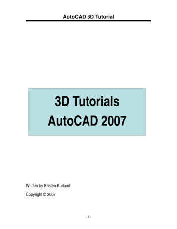
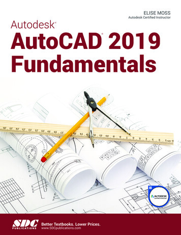
Autodesk AutoCAD 2019: FundamentalsDrawing Name: Begin a new drawingEstimated Time to Completion: 10 MinutesScopeStart a New drawing. Enable DYN. With ORTHO on, draw the object below. Drag theline in the desired direction and type the distance. Do not add the dimensions.Figure 1 – Line ExerciseSolution1. Start a New drawing by pressing the tab.2. Turn ORTHO on by pressing F8 until thecommand line says ‘ Ortho on ’.3. To see the geometric constraints as they are added, enable Infer Constraints orpress Ctrl Shift I.4. Invoke the Line command (l or line) on the Home ribbon.3-6
Drawing Lines5. Specify next point or [Undo]:Type 2.5 for the X-coordinate.Use the TAB key to advance to the Y-coordinate square.Type 3.5 for the Y-coordinate. Press ENTER .6. Specify next point or [Undo]:Drag the cursor downward and type 2.00 and press ENTER .You will see a small icon next to the line. This is a geometric constraint.A geometric constraint controls the geometry of an element. In this case, thesymbol indicates that the line is vertical.7. Specify next point or [Undo]:Drag the cursor to the right and type 1.00 and press ENTER .You should see another geometric constraint. This symbol indicatesthat the two lines are perpendicular to each other. Perpendicularmeans two lines form a 90 angle.8. Specify next point or [Close/Undo]:Drag the cursor downward and type 1.00 and press ENTER .Another perpendicular symbol is added.9. Specify next point or [Close/Undo]:Drag the cursor to the left and type 1.00 and press ENTER .3-7
Autodesk AutoCAD 2019: Fundamentals10. Specify next point or [Close/Undo]:Drag the cursor downward and type 1.00 and press ENTER .11. Specify next point or [Close/Undo]:Drag the cursor to the right and type 2.00 and press ENTER .12. Specify next point or [Close/Undo]:Drag the cursor up and type 2.00 and press ENTER .13. Specify next point or [Close/Undo]:Drag the cursor to the right and type 1.00 and press ENTER .14. Specify next point or [Close/ Undo]:Drag the cursor upward and type 2.00 and press ENTER .15. Specify next point or [Close/Undo]:Drag the cursor to the left and type 1.00 and press ENTER .3-8
Drawing Lines16. Specify next point or [Close/Undo]:Drag the cursor downward and type 1.00 and press ENTER .17. Specify next point or [Close/Undo]:Drag the cursor to the left and type 1.00 and press ENTER .18. Specify next point or [Close/Undo]:Drag the cursor upward and type 1.00 and press ENTER .19. Specify next point or [Close/Undo]:Right-click in the drawing area and select ‘Close’ or type ‘C’ andpress ENTER .The Close command will only work if you created a continuous line. Ifyou exited the line command and started again, then you have tomanually close the figure.Your completed figure should look like this.See if you can identify the different geometric constraints. Youshould see constraint symbols for vertical, horizontal andperpendicular.If the lines look crooked, then ORTHO is not on. You must begin again. Try to draw allof the line segments without starting and stopping the line command.The Close option only works if you draw in one continuous line. Otherwise, you cansimply draw a closing line from endpoint to endpoint.3-9
Autodesk AutoCAD 2019: FundamentalsParametric ConstraintsCommand LocatorParametric RibbonCommandParametricGeomconstraintCommand OverviewTo see the parametric constraints ribbon, you should have the Drafting & Annotation Workspace enabled.General Procedures1. To apply a geometric constraint, select the type of geometric constraint desired, then select theelement(s) to be constrained.Use inferred constraints - these are constraints which are automatically added as youdraw. Hide geometric constraints when you are not actively constraining your sketch. Typing U for Undo in the middle of the line command will undo the last linesegment. Typing U after completing line segments (at the blank command prompt)will Undo the entire line command. You can prevent constraints from automatically being applied by toggling OFFinferred constraints on the status bar or using the shortcut Ctl Shift I. 3-10
Drawing LinesDrawing Name: constraints1.dwgEstimated Time to Completion: 10 MinutesScopeOpen ‘constraints1.dwg.’ Mouse over a constraint. Show all Constraints. Add a constraint. Delete a constraint. Hide all Constraints.SolutionWhen the drawing is first opened, you should not see any geometricconstraints.The geometric constraints have been hidden. Their display hasbeen turned OFF.1. Mouse your cursor over the drawing WITHOUT selectinganything. Don't left click. As you mouse over the lines, youshould see a small symbol. The symbol indicates that ageometric constraint exists for that line. If no geometricconstraint exists, you will not see the symbol. Mouse over thesmall circle and notice that no symbol appears.3-11
Autodesk AutoCAD 2019: Fundamentals2. Activate the Parametric ribbon.3. Select Show All to display all the geometric constraints currentlyapplied.4. Use your left mouse button to rearrange the geometric symbols.5. Hold down the left mouse button and drag the symbol to a newposition.6. Place the left mouse button over one of the perpendicular symbols.Notice that it will display the two lines that are perpendicular.Let's move the small circle so it is concentric to the arc using ageometric constraint.A concentric constraint means that two or more arcs/circlesshare the same center point. The elements can have differentradii.When you apply a geometric constraint, the FIRST elementremains fixed and the SECOND element moves to beconstrained.On the Parametric ribbon:7. Select the Concentric constraint.You will see a small Concentric symbolindicating that you are going to beapplying that constraint type.There is a prompt asking you to selectthe elements to be used for theconstraint.8. Select the arc first and then the circle.3-12
Drawing LinesThe circle popped into the correct position.You also see the concentric symbol on the arc and the circle.9. Select the line indicated.On the ribbon:10. Select Delete Constraints.The perpendicular constraints on the selected line are deleted.11. Select the same line.12. Select Auto Constrain from the ribbon.This will add constraints to the selected line.What constraints do you think will be added?3-13
Autodesk AutoCAD 2019: Fundamentals13. A horizontal constraint is added.In order to add a perpendicular constraint - you need to select TWO lines.14. Select the perpendicular constraint.15. Select the small x in the symbol box.This hides the perpendicular constraint.It does not delete it.16. Select the vertical line.The perpendicular symbol will appear while the line is selected.17. To delete the perpendicular constraint, select it, right click and selectDelete.18. Press ESC to release the selection.19. Select the vertical constraint.You will see the Verticalconstraint icon and a prompt toselect the element where theconstraint is to be applied.20. Select the vertical line.You see a vertical constraint has been applied.You can only apply a vertical constraint if the perpendicular constraint has beenremoved. Too many geometric constraints on the same element is not allowed.21. Select Hide All.This hides all the geometric constraints.22. Close without saving.3-14
Drawing LinesDrawing Name: Line2.dwgEstimated Time to Completion: 10 MinutesScopeOpen ‘line2.dwg’ and draw the object shown in the example using the line command withPOLAR enabled. Polar settings have already been made to create the necessary angles.When you have completed the third segment, type C to close the object. Press ENTER torepeat the line command, press ENTER again, and see that the line picks up from thelast point selected.Solution1. Turn POLAR on.2. Left click on the down arrow nextto the Polar Tracking icon.3. Select Tracking Settings.4. Select the New button to add an additionalangle setting.3-15
Autodesk AutoCAD 2019: Fundamentals5. Type in 57.00 for the new angle value.6. Press OK.7. Left click on the down arrow next to the PolarTracking icon.8. Enable the 57.00 polar values.9. Invoke the Line command (l or line) from the Home ribbon.10. Specify first point:Pick a start point of the line with your left mouse button near the #1 onthe drawing.11. Specify next point or [Undo]:Pick a second point near the #2 on the drawing.As you draw your line up to the #2, look for the Tooltip indicating the 57degree angle.As you draw your line up to the #3, look for the Tooltip indicating the 0-degree angle.12. Specify next point or [Undo]:Move your mouse near #3 and click to complete thesecond line segment.13. Press ESC to exit the LINE command.14. Left click on the down arrow next to the PolarTracking icon.15. Enable the 30.00 polar values.3-16
Drawing Lines16. Select the LINE tool.17. Press ENTER and the line will startwhere you left off at Point #3.18. Specify next point or [Close/Undo]:Use Object Tracking to line up your end point and set the Polar Angle to 120-degrees.19. Specify next point or [Close/Undo]:Place the final line segment by selecting the ENDpoint of the first line near Point #1. When you closed your object did it complete the parallelogram? If not, you mayhave stopped and restarted the line sequence, in which case the close option willrefer to the new start point.Move your mouse as you work to see what line segments you have just completed.Click on ORTHO in the Status bar, or press the F8 function key, whichever ismore convenient at the time to create straight lines.Make a habit of using the ENTER key to complete your AutoCAD commands,and to repeat the last command used. Alternately, you may click the right mousebutton and select the Repeat option.In order for Polar Tracking to click to specific angle values, you have to have themset. Use Settings in the Polar Tracking dialog to add angles you want to use in yourdrafting.3-17
Autodesk AutoCAD 2019: FundamentalsDrawing Name: Begin a new drawingEstimated Time to Completion: 10 MinutesScopeStart a New Drawing using the acad.dwt template and draw the object shown in theexample using the line command with Cartesian Coordinates. When you havecompleted the third segment, type C to close the object. Press ENTER to repeat theline command, press ENTER again, and see that the line picks up from the last pointselected. Turn DYN off and ORTHO on for this exercise.Solution1. Invoke the Line command (l or line).2. Specify first point: Type 0,0 at the command line.3. Specify next point or [Undo]: Type 3,0.4. Specify next point or [Undo]: 3,25. Specify next point or [Close/Undo]: 4,26. Specify next point or [Close/Undo]: 1.5,67. Specify next point or [Close/Undo]: -1,28. Specify next point or [Close/Undo]: 0,29. Specify next point or [Close/Undo]:Right-click in the drawing area and select ‘Close’ or type ‘C’ or ‘CLOSE’ and press ENTER at thecommand line to create the final line segment.3-18
Drawing Lines If your drawing did not turn out properly, make sure you had DYN OFF. Tocheck your data entry, press F2 and the text window will open and you canreview your entries.Coordinate EntryCommand OverviewOnce the Units have been established, coordinates can be typed to specify points or distances. Always draw full scale. There are four ways to specify coordinates: absolute, relative,polar, and direct distance.Coordinate Entry MethodAbsolute CoordinatesOverviewThe x and y coordinates are determinedby an absolute Origin point of 0,0.Relative CoordinatesThe x and y coordinates reference the lastpoint selected in the drawing.Polar CoordinatesThe distance and angle specifiedreferences the last point selected in thedrawing.Direct DistanceSelect the first point, then drag the cursorin the desired direction and type thedistance.ExamplesX,Y1,5@x,y@3,5@distance angle@5 45Type the distance4General ProceduresUsing Absolute Coordinates:1. When prompted to specify a point, type the Absolute coordinates for x and y (x,y).2. Type the Absolute Coordinate for each successive point (x,y).Typical Example: Inserting a Title Block or an Externally Referenced Drawing at a specific location.Using Relative Coordinates:1. When prompted to specify a point, select a point in the drawing.2. Type the Relative Coordinate for each successive point (@x,y).Typical Example: Drawing a Rectangle.Using Polar Coordinates:1. When prompted to specify a point, select a point in the drawing.2. Type the Polar Coordinate for each successive point (@distance angle).Typical Example: Drawing lines or moving objects at a specified distance and angle other thanorthogonal angles.Using Direct Distance:1. When prompted to specify a point, select a point in the drawing.2. Turn ORTHO on and drag the cursor in the desired direction.3. Type the distance and press ENTER .Typical Example: Drawing lines or using the Move, Copy or Stretch commands.3-19
Autodesk AutoCAD 2019: Fundamentals Always use object snap for selecting specific points in the drawing.Remember to separate the x and y coordinates by a comma. Example: 1,5 means theabsolute coordinate where x 1 and y 5.It is not necessary to type the z coordinate when z 0.Angles are typically measured counterclockwise. Angle 0 is typically East.Precede Relative and Polar coordinate information with an @ sign (over the number 2 on thekeyboard).ORTHO should be on when using the direct distance method.When drawing lines, or moving objects at specific angles (other than with ORTHO on), typethe polar coordinate (example: @10 45) or use Polar Tracking Settings.Typing the minimum number of keystrokes is important for drawing efficiently. AutoCADwill fill in leading and trailing zeros and the appropriate Unit endings.AutoCAD will convert decimal equivalents to feet and inches.AutoCAD will assume inches, unless the foot mark ' is typed.The Coordinates Display can be turned on or off from the Status Bar by double clicking on it(LMB). If in the middle of a Draw or Modify command, a third option will display thedistance and angle.The DYN toggle can be used to display and enter coordinates.3-20
Drawing LinesDrawing Name: entry1.dwgEstimated Time to Completion: 5 MinutesScopeStart the line command. Draw the objects using the absolute coordinates in the order indicated.Connect the points using only the keyboard. Turn DYN off and ORTHO on.Solution1.Invoke the Line command (l or line).2. Specify first point:Type 1,1 at the command line and press ENTER . Notice where the first point of the line is created.3. Specify next point or [Undo]:Type 4,1 at the command line and press ENTER .4. Specify next point or [Undo]:Type 4,2 at the command line and press ENTER .5. Specify next point or [Close/Undo]:Type 8,2 and press ENTER .6. Specify next point or [Close/Undo]:Type 8,4 and press ENTER .7. Specify next point or [Close/Undo]:Type 1,4 and press ENTER .8. Specify next point or [Close/Undo]:Type 1,1 and press ENTER .9. Specify next point or [Close/Undo]:Press the ENTER key to end the command. You can also use the close option to complete the exercise rather than typing inthe final ‘1,1’.3-21
Autodesk AutoCAD 2019: FundamentalsDrawing Name: entry2.dwgEstimated Time to Completion: 5 MinutesScopeStart the line command. Draw the objects using the relative coordinates in the order indicated.Connect the points using only the keyboard.Solution1.Invoke the Line command (l or line).2. Specify first point:Type 1,1 at the command line and press ENTER .Notice where the first point of the line is created.3.Specify next point or [Undo]:Type @3,0 at the command line and press ENTER .4. Specify next point or [Undo]:Type @0,1 at the command line and press ENTER .5. Specify next point or [Close/Undo]:Type @4,0 and press ENTER .6. Specify next point or [Close/Undo]:Type @0,2 and press ENTER .7. Specify next point or [Close/Undo]:Type @-7,0 and press ENTER .8. Specify next point or [Close/Undo]:Type @0,-3 and press ENTER .9. Specify next point or [Close/Undo]:Press the ENTER key to end the command.Extra: What would you type in to create the shape in a clockwise fashion instead of counterclockwise direction? Try it.3-22
Drawing LinesDrawing Name: entry3.dwgEstimated Time to Completion: 5 MinutesScopeStart the line command. Draw the objects using polar coordinates in the order indicated.Connect the points using only the keyboard.Solution1.Invoke the Line command (l or line).2. Specify first point:Type 1,1 at the command line and press ENTER .Notice where the first point of the line is created.3.Specify next point or [Undo]:Type @3 0 at the command line and press ENTER .4. Specify next point or [Undo]:Type @1 90 at the command line and press ENTER .5. Specify next point or [Close/Undo]:Type @4 0 and press ENTER .6. Specify next point or [Close/Undo]:Type @2 90 and press ENTER .7. Specify next point or [Close/Undo]:Type @7 180 and press ENTER .8. Specify next point or [Close/Undo]:Type @3 270 and press ENTER .9. Specify next point or [Close/Undo]:Press the ENTER key to end the command.Extra: What would happen if you typed @-3 180 in step 3 in the exercise? Try it.3-23
Autodesk AutoCAD 2019: FundamentalsDrawing Name: entry4.dwgEstimated Time to Completion: 5 MinutesScopeStart the line command. Draw the objects using the direct distance method.Solution1.Invoke the Line command (l or line).2. Specify first point:Type 1,1 at the command line and press ENTER .Notice where the first point of the line is created.3.Specify next point or [Undo]:Toggle ORTHO ON at the Status bar.4. Specify next point or [Undo]:Drag the mouse to the right, type 3 and press ENTER .5. Specify next point or [Close/Undo]:Drag the mouse upward, type 1 and press ENTER .6. Specify next point or [Close/Undo]:Drag the mouse to the right, type 4 and press ENTER .7. Specify next point or [Close/Undo]:Drag the mouse upward, type 2 and press ENTER .8. Specify next point or [Close/Undo]:Drag the mouse to the left, type 7 and press ENTER .9. Specify next point or [Close/Undo]:Drag the mouse downward, type 3 and press ENTER .10. Specify next point or [Close/Undo]:Press the ENTER key to end the command.3-24
Drawing LinesEraseCommand LocatorHome/Modify PanelEraseCommandEraseAliasECommand OverviewErase deletes selected objects. Press ENTER after selecting the objects to erase to execute thecommand. Type OOPS to bring back the last set of erased objects, even if other objects were drawn sincethe last erase.General Procedures1. Begin the erase command by selecting the Erase icon from the Modify Toolbar/Ribbon or typingE at the blank command prompt.2. Place the cursor over the objects to erase and pick (LMB).If the cursor is not over an object, a selection window will appear. Make theother corner of the selection window. A Selection Window made from Left to Right will select only the objectscompletely in the window. This is called a selection window. A Selection Window made from Right to Left will select all objects thewindow crosses. This is called a selection crossing. Typing All (and pressing ENTER ) will select all objects in the drawing toerase. Press ENTER to execute the command. 3-25
Autodesk AutoCAD 2019: FundamentalsDrawing Name: erase1.dwgEstimated Time to Completion: 5 MinutesScopeErase the objects in the drawing. Draw some more lines. Type OOPS to bring back the lastset of erased objects. OOPS is different from UNDO. UNDO backs up the last set of issuedcommands. OOPS restores the last set of erased elements even if there was more than onecommand issued before you typed OOPS.Solution1. Invoke the Erase command (e or erase) on the Home ribbon.2. Select objects:Select the objects by typing ALL and pressing ENTER , picking each line individually, or usingthe Window method. When all the objects are highlighted, press ENTER to execute theErase command.3. Invoke the Line command (l or line).4. Specify first point:Use your LMB to pick the start point of a line segment. Select any location on the drawing.5. Specify next point or [Undo]:Continue to use the LMB to create lines on the drawing.6. Specify next point or [Close/Undo]:Press the ENTER key to end the line command.7. Type OOPS at the command line and press the ENTER key. Select all the objects to erase, then press ENTER to execute the command.To remove an object from the selection set, hold down the shift key and selectthe object again. See that it is removed from the selection set. Then press ENTER .3-26
Drawing LinesReview Questions1. How do you turn on the display of the coordinates in the status bar?2. A user enters LINE 1,1 and then @0,2 .what type of coordinates is she using?3. To make sure you will always draw a straight line, what tray button should be enabled?4. When using the POLAR method of coordinate entry, which tray button should be enabled?5. When entering direct coordinates, which tray button should be disabled?6. What is the difference between OOPS and UNDO?3-27
Autodesk AutoCAD 2019: FundamentalsReview Answers1. How do you turn on the display of the coordinates in the status bar?Left click on the STATUS bar options icon and enable Coordinates2. A user enters LINE 1,1 and then @0,2 .what type of coordinates is she using?Relative3. To make sure you will always draw a straight line, what tray button should be enabled?ORTHO4. When using the POLAR method of coordinate entry, which tray button should be enabled?POLAR5. When entering direct coordinates, which tray button should be disabled?DYN6. What is the difference between OOPS and UNDO?UNDO reverses the last command entered. OOPS restores the last item(s) erased or deleted fromthe drawing.3-28
Start a New drawing. Enable DYN. With ORTHO on, draw the object below. Drag the line in the desired direction and type the distance. Do not add the dimensions. Figure 1 – Line Exercise. Solution. 1. Start a New drawing by pressing the tab. 2. Turn ORTHO on by pressing F8 until the