Transcription
VRVReferenceGuide01.17
About Daikin:Daikin Industries, Ltd. (DIL) is a global Fortune 1000company which celebrated its 90th anniversary inMay 2014. The company is recognized as one of the largestHVAC (Heating, Ventilation, Air Conditioning) manufacturersin the world. DIL is primarily engaged in developingindoor comfort products and refrigeration systemsfor residential, commercial and industrial applications.Its consistent success is derived, in part, from a focuson innovative, energy-efficient and premium quality indoorclimate and comfort management solutions.A WORLD LEADINGMANUFACTUREROF HVAC PRODUCTSFOUNDEDI N1 9 2 4OVER 60,0000 DAIKIN VRV SYSTEMSOPERATINGTHROUGHOUT NORTH AMERICARESEARCHDEVELOPMENTOVER 300 MILLION
TABLE OF CONTENTSSYSTEM OVERVIEWThe Features of VRV . 6Key Points For Selection . 8Capacity Range & Operating Limits . 12Nomenclature . 15SYSTEM SELECTIONIndoor Unit Range . 18Indoor Unit Consideration .20Zoning VRV Systems with DZK . 24Heat Pump or Heat Recovery? .26Air Cooled or Water Cooled? .29Solutions For Ventilation .32DESIGN OPTIMIZATIONSystem Zoning .36Branch Selector Boxes .40Single or Multi BSV Boxes? . 41Piping Sizes and Optimization .43Outdoor Unit Installation Space .45Heat Pump Changeover . 47CONTROLS & STANDARDSControls Portfolio .52Local Control Options .56Featured Controls .57Codes & Standards .59Tips & Considerations .60Future Documents & Data . 61
SystemOverview
The Features of VRVFeatures & Benefits to Using VRVA VRV system is similar to a chiller but circulates refrigerantto each zone instead of waterA VRV heat pump system has performance and designattributes similar to a 2 pipe chillerA VRV heat recovery system has performance and designattributes similar to a 4 pipe chiller system¡ Industry Leadership since 1982, VRV is a registered TM¡ 8 development series and 4 generations of VRV technology¡ Scalable project opportunities with modular design¡ Broad coverage of most vertical markets and climates¡ Tested and Rated in accordance with AHRI Std 1230¡ Individual zone control for Advanced zoning capabilities¡ Can operate up to 64 indoor fan coil units¡ Auto charging function¡ Continuous heating during defrost operation¡ Flexible piping limitations to meet a variety of building needs¡ Excellent energy efficiency, especially at part load conditions (IEER)¡ Daikin’s optimized scroll compressor designed for R-410A provides¡¡¡¡a quiet, reliable energyefficient operationAnti-corrosion treatmentstandard on exterior metalparts and heat exchangerFully compatible with thecomplete Daikin controlsuite including iTC, and iTMTie in to open protocolBuilding Automationsystems through LonWorks and BACnet gateways10-Year Limited Parts Warranty** Complete warranty details are available from your local Daikin manufacturer’srepresentative or distributor or online at www.daikincomfort.com.6
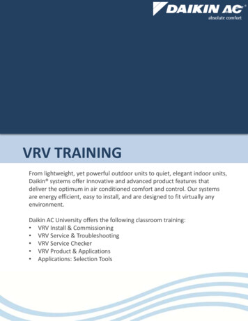
SYSTEM OVERVIEWThe Features of VRV (cont.)The benefits of VRV equipment can categorized three core features:Simple Modular DesignIndoor UnitsPipingControlsSYSTEM SELECTIONOutdoor UnitThe ease of both design and installation has been a major factorin the success of VRV in the global market. Simple methodologysees VRV regularly utilized in all project sizes from 3 ton to several1,000 ton.Ultra-High Energy EfficienciesIEER (Integrated Energy Efficiency Ratio)2422201816141210VRV IV HRVRV IV HPASHRAE 90.1 20106DESIGN OPTIMIZATION2826Direct expansion systems(those that use refrigerant todirectly condition the space)provide an extremely efficientmethod of heat exchange.SPECIFICATIONS& ACCESSORIESIEER Ratings30Inver ter controlled compressors also ensure optimizedsystem performance.8 10 12 14 16 18 20 22 24 26 28 30 32 34 36 38Optimum refrigerant & systemcontrol sees Daikin VRVfar exceed industry energy efficiency requirements.Nominal Capacity (Ton)Wireless unitControllerRoom or GroupControllerCONTROLS ANDSTANDARDSExceptional Comfort controlCentralControllerBMS InterfaceFrom controlling temperature in individual areas to the remotemonitoring and control of multiple sites, the Daikin VRV systemhas a wealth of propriety control options to cover all end userrequirements and ensuring exceptional levels of comfort control.7
Key Points for SelectionSystem Diversity vs Connection RatioOptimizing VRV System Selection¡ The most successful users of VRV equipment understand theimportance of a fully optimized design¡ A key factor that ensures optimized VRV equipment selection isto understand the correlation between SYSTEM DIVERSITY &CONNECTION RATIOA fully optimized design can realize a number of benefits:¡ Cheaper equipment & installations costs¡ Less outdoor unit footprint¡ A more energy efficient system¡ Far better control of room temperature¡ A significant increase in the probability ofwinning a projectPeak Loads & Block LoadsThe first step to optimization is to understand the different loaddemands of the equipment to be selected:Unit TypeSelection ScopePEAK LoadBLOCK Load8Selection ApproachIndoor units should besized to deliver the PEAKloads (total and/or sensible)of the area it is to serve,at the entering air designconditions determined by thebuilding load calculationsOutdoor units should beselected to meet the BLOCKCooling & Heating capacities(The Maximum Load demandof all attached indoor unitsat a given time of day)determined by the sameLOAD Calculations
SYSTEM OVERVIEWDiversity & Connection Ratio - What’s the Difference?Connection Ratio:¡ Both indoor & outdoor units have a Capacity Index number(e.g. FXMQ30PBVJU indoor unit & RXYQ192TTJU outdoor unit) ODU indexnumber CONNECTIONRATIOSYSTEM SELECTIONTotal sum of IDUindex numbers¡ This ratio is defined as a percentage:– Example: 8 x FXMQ30P connected to 1 x RXYQ192T 240 / 192 1.25– Therefore the Connection Ratio 125%System Diversity:DESIGN OPTIMIZATIONSPECIFICATIONS& ACCESSORIESDIVERSITY is the difference between the Maximum SystemLoad demand and the Maximum Capacity of the outdoor unit,at design conditions¡ The VRVXpress tool can define diversity - also as a percentageCONTROLS ANDSTANDARDSExample: 8 x FXMQ30P connected to 1 x RXYQ168T– Maximum Load required at any given time: .170,269 btu– Maximum Capacity of the ODU at design conditions: . 166,315 btu– VRV defines the DIVERSITY of the system at: .-2%¡ In this example, if the maximum load is called for, the outdoor unitwill fall short of demand by 3,954btu – This VRV design has a2% system diversityTo summarize: Connection Ratio does NOT indicate the diversityof a VRV system. Use of the VRVXpress selection tool willindicate clearly if selected equipment has a system diversityor not.9
Key Points for Selection (cont.)Obtain Project DataBefore selection of any VRV system, a minimum amount ofinformation is required for accurate equipment selection and toapply an optimized designFor an accurate selection of indoor units the following information is required:DESIGN AIR ConditionsPEAK Cooling Loads PEAK Heating Loads The dry & wet bulb temperaturesentering the coil¡ Engineers will usuallyprovide both Total &Sensible loads whichshould be entered¡ However it is possibleto select equipmentusing only Total orSensible load¡ Required wheneither Heating isthe dominantoperation or theheating designcondition isbelow 32 F¡ Also known as “air-on” or“mixed air” conditions¡ Nominal conditions aretypically 80 F db & 67 Fwb but rarely reflectactual conditions¡ Design air-on can alsobe given as db/RH%(e.g. 74 F & 50% RH)For an accurate selection of outdoor units the following information is required:AMBIENT ConditionsThe design ambient temperature forthe location of the project¡ Both engineers and D&B contractorsshould have this information¡ If this information is not at hand then useASHRAE standard design conditions forthe location10PIPE LENGTHThe estimated distance between theoutdoor unit and the furthest indoor unit¡ This is the linear length from onepoint to another NOT the totalamount of piping¡ Both engineers and D&B contractorsshould be able to pin point theoutdoor unit location¡ Be sure to also establish whetherthere is any vertical height betweenoutdoor & indoor units
SystemLimitsFXDQ, FXMQ P,FXAQVRV-IV W-SeriesAll other modelsSingleVRV-SAll Indoor Units200%130%160%200%TripleModuleN/A130%130%SYSTEM SELECTIONDualModuleSYSTEM OVERVIEWVRV IV Heat Pump & HeatRecovery, Aurora SeriesN/A¡ On VRV-III, if systems operated 130% indoor unit thermo-ON, all FCU wereset to low fan speed. On VRV IV this function can now be overridden atcommissioning stage¡ For FXFQ 07, 09 models, connection ratio is limited to 296SPECIFICATIONS& ACCESSORIES077.5DESIGN OPTIMIZATIONIndoor Unit SizeIndoor UnitCapacity IndexVRV System Selection - Avoid the common pitfallsCommon MistakeBest PracticeVRV is a chiller circulating refrigerantinstead of waterIt’s a Zoning system thus an Indoorunit in EVERY roomDesign VRV systems using same approachas VAV or WSHPVRV is a “Ductless System”More than 55% of units used inNorth America are Ducted types!Upgrade Indoor Units to the nextcapacity sizeUse accurate load calc values and trustselection softwareOptimum selection of Controlsis not importantBe knowledgeable on controls capabilities– minimize BAS or even elimination of BASis often possibleThe entire application needs tobe VRVUse VRV where it makes sense for thecustomer & projectCONTROLS ANDSTANDARDSThinking VRV is just a “big”multi split DX system11
Capacity Range & Operating LimitsODU Capacity Range & Piping Limitations48 (4)60 (5)1/208172 (6)1120 (10)264 (22)288 (24)HEAT PUMP3/460V/60Hz240 (20)3/208-230V/60Hz192 (16)8144 (12)1122025292HEAT RECOVERY168 (14)3332312 (26)343384 (32)3408 (34)5646464Type168 (14)216 (18)252 (21)UnifiedHP or HR144 (12)3/208-230V/60Hz3/460V/60Hz72 (6)84 (7)360 (30)384 (32)62364Aurora Series & 575V VRV IV units are currently onlyavailable in an air-cooled heat recovery model.1. Total capacity index of connectable indoor units forVRV IV must be within 50% - 200%.2. Aurora Series & 575V VRV IV have only 1 compressorper module.3. Total capacity index of connectable indoor units forAurora Series and 72 MBH 575V VRV IV must be within70% - 200%. Total capacity index of connectable indoorunits for 575V VRV IV 96MBH – 384MBH must be within50% - 200%.# ofModules# ofCompressorsMax. #IDU111211142224222933363336Total capacity index of connectable indoor units must be within 50%-130%.12Voltage58456 (38)Voltage4145336 (28)432 (36)Capacity2245646264 (22)333749624325458360 (30)2529312 (26)54336 (28)2192 (16)240 (20)1620168 (14)216 (18)Aurora12288 (24)494Max. # IDU357541372Aurora16102144 (12)5751120 (10)16172 (6)# of Modules /Compressors 296 (8)230/60Hz96 (8)216 (18)Max. # IDU1TypeCapacityMBH(Tn)575V/3/60Hz36 (3)Voltage# of ModulesCapacityMBH(Tn)Aurora Series & 575V# of CompressorsOutdoor Unit Range
SYSTEM OVERVIEWCommunication Wiring should be 18-2AWG stranded,no polarity, no shieldingmaximum linear distance 3280ft, maximum total distance 6560ft¡ Maximum linear distance in the example below is the longest of either¡ (A) to (C), (A) to (E), (A) to (G) or (C) to (G)SYSTEM SELECTION¡ Maximum total distance is (A to F) (B to C) (D to E) (F to G)¡ Each local controller (H to C) can run up to a distance of 1640ftCBHEDSPECIFICATIONS& ACCESSORIESDESIGN OPTIMIZATIONAGFAmbientHeat PumpHeat Recovery122 FEntering Water-4 F-13 F-22 FHEATINGCOOLINGCOOLINGAURORA Series Standard Operating Range10 FRange inCooling95 FSIMULTANEOUS23 FHEATING77 F27 FCONTROLS ANDSTANDARDSTemperature Limits113 FRange inHeating*14 FIndoorTemperature50 F 59 F80 F 82 F* Conditions apply when entering water temperature isbelow 50ºF. Refer to your local Daikin Representativefor further information.VIA extended capacity tablesVIA technical cooling functionCooling operation for VRV IV Heat Pump singlemodule systems (RXYQ72/96/120/144/168T) canbe extended down to 10 F, from the standardlimitation of 23 F under defined conditions.Contact your local Daikin manufacturer’srepresentative or distributor for details.13
Capacity Range & Operating Limits (cont.)Refrigerant Piping LimitationsABCDELiquid LineMax iesVRV-IVW-SeriesWaterCooledVRV-IV S(36)VRV-IV icalRise130(295)*130(195)*130(195)*1309898DFrom 032801640980820984* Setting adjustment on condensing unit required.** Fan coil distance differentials need to be met† Possible refrigerant noise can be mitigated (via setting adjustments on ODU)when linear length exceeds 390FT.14
SYSTEM OVERVIEWNomenclatureHow to Read Model NumberIndoor UnitsFXMQ24PVJUIndoor UnitCategoryFX: VRV systemindoor unitSYSTEM SELECTIONStandardcompatibility symbolU: United States of AmericaPower supply symbolVJ: 1 phase, 208/230V, 60 HzIndoor unit typeExample:M: Concealedceiling ductedSeries/ Design ChangeMajor Design ChangeZ: 4-way ceilingmounted cassetteSPECIFICATIONS& ACCESSORIESDESIGN OPTIMIZATIONNominal cooling capacityExample:Btu/h(Tons)24 24000 (2)60 60000 (5)Refrigerant typeQ: R-410AOutdoor UnitsROutdoor UnitCategoryR: Air cooledRW: Water cooledXY: Heat PumpEY: Heat RecoveryXT: Heat Pump (1ø)EL: Heat Recoverycold climateQ192TAYCUStandardcompatibility symbolU: United States of AmericaPower supply symbolTJ: 3ø, 208/230V, 60 HzYD: 3ø, 460V, 60 HzYC: 3ø, 575, 60 HzVJ: 1ø, 208/230V, 60 HzCONTROLS ANDSTANDARDSMode of OperationELT Series / Design ChangeMinor Design ChangeSeries / Design ChangeMajor Design ChangeRefrigerant typeQ: R-410ANominal cooling capacityExample:Btu/h(Tons)192 192,000 (16)456 456,000 (38)15
SystemSelection
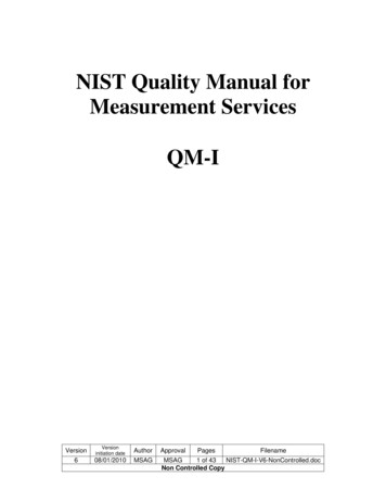
Indoor Unit RangeSizes & Accessories Available of all IDU’sTYPERound-flowCeiling mountedcassette4 way blow ceilingmounted cassetteA Complete Line Up of VRV Indoor UnitsUnder CeilingMounted CassetteCeiling-MountedCassette(Single Flow)Slim DuctedCeiling ConcealedDC DuctedConcealed CeilingLarge CapacityCellingConcealedFlat PanelWall MountedMODELFXFQ-TUNIT Q0718092412FXMQ FXUQFXMQ MFXAQFXHQ24Ceiling SuspendedFloorMountedConcealedFloorStandingMulti 448123054FXTQ-TA Filter Included Pump Included Filter Options Pump Options OA Connection07 Size Available363660
SYSTEM OVERVIEWFXEQ STD HumidifierAdaptor PCB STD EconomizerOption DZK (Zoning Kit) ElectricHeater KitsDESIGN OPTIMIZATIONOAConnection KitSPECIFICATIONS& ACCESSORIESMERV 13 Filters Presence Sensor CONTROLS ANDSTANDARDSSelf CleaningFilterHail GuardFXZQ FXTQFXUQFXNQFXMQ-MFXMQ-PB FXLQ FXHQ FXDQAUX HeatAdaptor PCBMERV 8 FiltersSYSTEM SELECTIONFXFQ-TOptionsFXAQOptional Indoor Unit Accessories availableto enhance your Daikin VRV solution: Outdoor Unit Accessory (RXYQ & REYQ only)19
Indoor Unit ConsiderationsCASSETTE UNITS provide the best combination of economicinstallation with a good level of flexible project design. Fresh airsupply is possible but limitedConsiderations:¡ Is there a ceiling void space?¡ What is the height of the void space?¡ What type of ceiling (grid or hardboard)?*¡ Is there a requirement to introduce fresh air?*Note: In hard-board ceilings, service hatches are requiredCassette RangeFXZQModelHeightAirThrowMax.O.A.All1113 /16 "12ft(per outlet)3% ofunit AFR07 309 11/16 "36 4811 /16 "14ft(per outlet)20% ofunit AFR*18 24713 /16 "12ft(per outlet)30 36713 /16 "14ft(per outlet)07 24111/16 "†15ftFXFQ5FXUQFXEQ†less than 10 inches in void spaceApplication Examples:20N/A15%*requires outdoor air kit (or else only 3%)FXZQsmall offices – 2' x 2' ceiling gridsFXFQlarge open plan areas – shallow void spacesFXUQretail outlets – restricted or no void spacesFXEQhotel bedrooms, perimeter retail and offices
SYSTEM OVERVIEWDUCTED units offer the ultimate in flexibility of design, airdistribution and integration of ventilation. It also tends to bethe most expensive installed cost option. However cost canbe minimized by serving multiple rooms with a single unit the loss of individual room units can be countered withthoughtful control design.SYSTEM SELECTIONConsiderations:¡ Is there a ceiling void space?¡ What is the height of the void space?¡ What level of ESP is likely to be required¡ Is there a requirement to introduce ventilation intothe space via the FCU?¡ What level of control is required?DESIGN OPTIMIZATIONDucted RangeModelFXDQ07 1218 24Height7 7/8 "07 15FXMQ-P18 481113/16"0.17"0.80"20% ofunit AFR0.56"18 1/8 "CONTROLS ANDSTANDARDSApplication Examples:72 96Max. O.A.0.12"0.40"54FXMQ-MMax. WGSPECIFICATIONS& ACCESSORIESNote: Multiple rooms can be served by one unit (See DZK control section)0.95"(1.1" 230V)FXMQ-PMost applications – multiple room zoningFXMQ-MLarge open plan areas – high ESP requirementsFXDQBulkheads – hotels – assisted living21
Indoor Unit Considerations (cont.)CONCEALED units offer the opportunity to hide away theequipment when there is no ceiling void but the client doesnot wish to use exposed units or else has similar equipmentexisting and sees the benefit of retro fitting with minimumdisruption and expense.In areas where heating is the primary role of the system, floorstanding units are sometimes installed around the perimeter ofa building for optimum air flow.Considerations:¡ Is there an existing unitary type system?¡ Is heating the primary requirement?¡ Does the client prefer not to ‘see’ the units?¡ Is there a requirement to introduce fresh ll24Minimal10%AFR*09 - 3645"42 - 4853 ½"0.9"20%AFR54 - 60Application Examples:58"FXNQPerimeter heating – hallwaysFXTQCondo’s – closet spaces – retrofits*Via underside - no duct22
SYSTEM OVERVIEWEXPOSED units usually offer the client the most economicalinstalled cost solution on a VRV system. These types of units aremost often used when there are budget constraints or where anarea has no void space/enclosure to conceal other unit types.None of these units have integral condensate pumps fitted.SYSTEM SELECTIONConsiderations:¡ How big is the space?¡ Where can the unit be located?¡ Is piping / condensate run clear?¡ Is the client accepting of exposed units?All20'FXAQAll13'FXLQAll7'Application Examples:TypicalO.A.N/ANONEFXHQClassrooms – retail – restaurantsFXAQHotels – small officesFXLQPerimeter heating – condos – churchesSPECIFICATIONS& ACCESSORIESFXHQMax.WGCONTROLS ANDSTANDARDSApprox.AirThrowDESIGN OPTIMIZATIONModelExposed Units23
Zoning VRV systems with DZKVRV Meets VAV - Features & BenefitsDZK - Daikin Zoning KitThe DZK solution increasest he f le x ib i l i t y o f V R Vapplications by allowingmultiple zones to be servedby one indoor unit fan coilwhile still providing individualtemperature control.Up to 6 separate dampers supply variable air flow to the zones inresponse to individual zone thermostats.Zoning BoxThe zoning box is a plenum with motorizeddampers that constantly modulate theconditioned air flow into each zone throughstandard ductwork, in response to the demandfrom the individual zone thermostat.Main ThermostatThe main thermostat is a wired color touchdisplay master unit used to configure the DZKsystem. It can also be used as the thermostatfor one or all of the zones.Zone ThermostatThe zone thermostat is a wireless, batterypowered, touch display unit that is used forone zone. Each zone thermostat monitors andallows the user to select a comfortable roomtemperature, and program or adjust the controlfunctions for the room.DZK BACnet Gateway ModuleThe DZK BACnet Gateway module allowsindividual room control via any BACnet/IPcompatible Building Management System.24
SYSTEM OVERVIEWStandard Ducted Set-UpSYSTEM SELECTIONAdvantages¡ Reduces system hardware cost - fewer Indoor units required¡ Increases comfort levels by allowing more individual zone control¡ Reduces installation expense and maintenance costsDESIGN OPTIMIZATION¡ Reduces the amount of refrigerant required in the installationSPECIFICATIONS& ACCESSORIES¡ Increases the flexibility of the VRV application designDucted Set-Up with DZKCONTROLS ANDSTANDARDSZoning Box RangeProduct ReferenceCompatibleDucted UnitDZK030E4DZK030E5FXMQ15PB FXMQ24PBDZK048E4DZK048E6FXMQ30PB FXMQ54PBNo. ofAir Duct Outlets4 x ø8"5 x ø6"4 x ø8"6 x ø6"Number of Zones2 to 42 to 52 to 42 to 6Note: The FXMQ indoor unit must still be connected to a BRC1E73 room controller25
Heat Pump or Heat Recovery?The Various Heat/Cool Changeover OptionsHeat Pump¡ The 2 pipe Heat Pump system is the equivalent of a 2-pipe chilledwater system¡ A heat pump system provides the means of heating OR cooling atany given time¡ Multiple heat pump systems can be zoned and will work independentlyof each other¡ When demand is met by an indoor unit the unit will work on fan only or thefan will cycle on/off until demand returns or mode change occursCoolingCoolingHeatingHeatingHeat Recovery¡ The 3 pipe Heat Recovery system is the equivalent of a 4-pipe chilledwater system¡ A heat recovery system has the ability to provide simultaneous heatingAND cooling¡ When both heating and cooling occur simultaneously, system and buildingenergy can be better utilized¡ When demand is met by an indoor unit the unit will work on fan onlyor the fan will cycle on/off until demand returnsCooling26CoolingHeatingHeating
SYSTEM OVERVIEWShould I Use Heat Pump or Heat Recovery?There are three main factors that dictate whether a HP or HRsystem should be selected. All these factors should be consideredin each case to determine an appropriate selection:SYSTEM SELECTIONClimate Zones of North AmericaSubarctic / ArcticSPECIFICATIONS& ACCESSORIESDESIGN OPTIMIZATIONVery CONTROLS ANDSTANDARDSGEOGRAPHYThe location or the project will often dictate what type ofsystem will be required. Projects in temperate climates tend touse Heat Recovery due to the changeable load demands thatcan occur through the course of a day. However areas withdefined seasons or little demand for simultaneous heating orcooling throughout the year will usually utilize Heat Pump.27
Heat Pump or Heat Recovery? (cont.)BUILDING LAYOUTSites with open plan areas and/or similar orientation will oftenbe satisfied by a heat pump system, irrespective of geography.On the other hand, if the site has many aspects, individualrooms and/or heat loads, this may define the client requirementtoward heat recovery. Differing internal room load demandsmay see the need for cooling for longer periods of the year.OCCUPANCYThe type of end user will often trump any other consideration.Typically a multi-tenanted site will require a heat recovery systemas the ability for individual mode control is paramount. Typicalexamples of this include hotels, assisted living, condos as wellas offices. It is always important to establish from the outset if anoffice application is to have multiple ngHEATRECOVERYUltimately there are many applications where the answer will beboth Heat Pump AND Heat Recovery28
SYSTEM OVERVIEWAir Cooled or Water Cooled?Factors that Benefit the use of VRV-IV W-SeriesAir to air VRV systems make up the majority of VRVinstallations This is due to the following:¡ Ease of installation (no water system required)¡ Less initial capital costsSYSTEM SELECTIONHowever Water Cooled VRV can have certainadvantages:¡ Greater energy efficiencies¡ Localized CU installation(reduced pipe runs)These advantages come in to playwhen the following are present:SPECIFICATIONS& ACCESSORIESDESIGN OPTIMIZATION¡ An existing chilled water loop¡ Extreme ambient conditions¡ An ability & desire to utilize alocal geothermal sourceInternal PlateHeat ExchangerWater Cooled VRV - Existing Water LoopCONTROLS ANDSTANDARDSBy utilizing anexisting water loopin the building, theadvantages of greaterenergy efficiency canbe promoted withouthaving to offset capitalcosts. In additionVRV-IV W-Series CUsare usually locatedlocally to the area theyare serving and willBoiler Tower Water Looptypically attach to thewater loop already running through the building. This negatesthe need to run copper piping through risers to a remoteplant space (be aware that VRV-IV W-Series CUs are internalmounting units).29
Air Cooled or Water Cooled? (cont.)Water Cooled VRV - GeothermalClosed Loop Buried in GroundA ground-source VRVheat pump system combinesthe advantages of bothtechnologies into onesystem, making it oneof the most efficient HVACsystems available andachieving savings overeither GSHP or VRF on theirown. The constant ambientconditions below groundalso ensure that these savingsare realized year round.There are two main typesof systems: closed loopand open loop. Closed loopsbury water pipes eitherin solid ground or in a watersource (like a pond or lake).An open loop draws fromgroundwater, like a well, andreturns it back to source.Closed Loop in Surface WaterOpen Loop using Ground Water30
SYSTEM OVERVIEWDesign Criteria:Water loop design is the responsibility of the engineer.However, two facts are needed from Daikin:The minimum & maximum entering water temperatures:50 F-113 F for Cooling27 F-113 F for Cooling on a Geothermal System50 F-113 F for Heating14 F-95 F for Heating on a Geothermal SystemSYSTEM SELECTION¡¡¡¡A suitable water flow rate:¡ 13.2gpm to 39gpm per module Boiler & Tower SystemSPECIFICATIONS& ACCESSORIESDESIGN OPTIMIZATION¡ 21gpm to 39gpm per module on a Geothermal System).* (Be aware that conditions need to be met when EWT for heatingis required below 50 F – seek assistance for these applications)Other consideration:¡ When VRV is to be applied with an open loop system, a 3rd partyCONTROLS ANDSTANDARDSheat exchanger is required to ensure the plate heat exchanger ofthe VRV condensing unit operates in a closed loop system.¡ The VRV condensing units have a heat output of approx. 2400btu’s.Where multiple units are placed in an enclosed area, any potentialheat build up must be addressed (either with adequate ventilationor even a fan coil unit).¡ From the CU pipe connection to the fan coils, the equipment,controls & selection process is identical to air cooled VRV.31
Solutions for VentilationRange & Limitations of our Ventilation OptionsCFM300100015002000250030005000750010000 FXMQ MF OAProcessingUnit630 – 1230DaikinVAM -300-1200Energy RecoveryVentilatorDVS DOAS AHU Unit 670 – 4000AHU Integration Kit(2-16 ton)Interlaced Coil up to34 ton (3 kits on oneHP system)Daikin AppliedDestiny AHU Only 600-15000 cfm optionsVision AHU Only 900-100,000 cfm optionsRebel Rooftop (DOAS)6-28 tons – 900 - 7,500 cfmMaverick II Rooftop(DOAS) 15-75 tonor 4500 - 23,000 cfm32
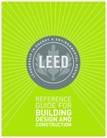
SYSTEM SELECTIONBasic Rules1. COOLING: Any percentage of OA can be used as longCoolingHeating70DESIGN OPTIMIZATION110as the resulting mixed air is between 57 and 77 FWBand 80% RH or lower.HEATING: Any percentage of OA can be used as longas the resulting mixed air is between 59 and 80 FDBand 80% RH or lower.SPECIFICATIONS& ACCESSORIES2.10060302040103020Range for warming up operation40Range for continuous operation50Outdoor Temperature ( FWB)60Range for pull-down operationRange for continuous operation7050CONTROLS ANDSTANDARDSOutdoor Temperature ( FDB)908050607080Indoor temperature ( FWB)90050SYSTEM OVERVIEWTypically Daikin equipment has been applied using a standard ruleof thumb that a maximum of 20% OA should be used for ducted fancoil units (FXMQ, FXDQ and FXNQ). However, this practice is notalways applicable as this rule of thumb is based upon introducingOA at nominal conditions.607080Indoor temperature ( FDB)90Note: Space temperature sensing should be done via the room zone controller orremote sensor kit if a “mixed air” approach is taken.33
Solutions for Ventilation (cont.)Method1. Untreatedventilation issupplied directlyto the indoor unit2. Small projectswhere low CFMvolumes arerequired3. Projects withbudget constraints4. Suitable for mildclimatesFXMQ1. Pretreatedventilation issupplied directlyto the indoor unit2. Small to mediumapplications3. Suitable for allclimates4. Allows for sharingload betweenventilation systemand VRV systemVAM5 F – 122 FDBNo LimitsFXMQ-MF23 FDB – 90 FWB(50 FDB – 82 FWB)50 - 100 - (130)%10 - 30 - (50)%EKEXVFCBA 50 FDB– 95 FDBFCB 90 -
PIPE LENGTH The estimated distance between the outdoor unit and the furthest indoor unit ¡ Both engineers and D&B contractors should have this information ¡ If this information is not at hand then use ASHRAE standard design conditions for the location ¡ This is the linear length