Transcription
Sepic Converter Design and OperationSubmitted 5/1/14 in partial completion of the requirements for aBS degree from WPIByGregory SharpAdvisor: Alex Emanuel
Table of contentsI) AbstractII) IntroductionIII) Topologya) Operationb) Specificationsc) Duty Cycle Calculationsd) Inductor Calculationse) Simulation resultsIV) Potentiometer Controlled PWMa) PWM Demonstrationb) Circuit diagramc) Simulation resultsV) Feedback Controlled PWMa) Feedback Flowchartb) Feedback Results at Various Levels of GainVI) SummaryVII) References23446677101213131516161920Table of FiguresFig 3.1 SEPIC operationFig 3.2 SEPIC SimulationFig 3.3 Graph of Vout and PulseFig 3.4 Graph of ICout, IL1 and PulseFig 3.5 Graph of VoutFig 3.6 Graph of Pout and PinFig 3.7 Graph of Vout, D and VCin with Vin 10VFig 4.1 Graph of Triangle wave and Sinusoidal control waveFig 4.2 Graph of controlled square waveFig 4.3 Labelled schematic of SEPIC converter using a potentiometer to control PWM.Fig 4.4 Graph of 555 and Triangle waveFig 4.5 Graph of Comparator output to MOSFET, Triangle Wave and Potentiometer Control SignalFig 5.1 Flow chart for feedback operationFig 5.2 Graph of Vout, as Vin increases. Gain is almost zeroFig 5.3 Graph of Vout, as Vin increases. Gain is too lowFig 5.4 Graph of Vout, as Vin increases. Gain is too highFig 5.5 Graph of Vout, as Vin increases. Gain is at a good value1455588912121313141617171818
I) AbstractThe purpose of this project was to design and optimize a SEPIC dc/dc converter (SingleEnded Primary Inductance Converter). The SEPIC converter allows a range of dc voltage to beadjusted to maintain a constant voltage output. This project talks about the importance of dc-dcconverters and why SEPIC converters are used instead of other dc-dc converters. This projectalso goes into detail about how to control the output of the converter with either a potentiometeror feedback to show how it can be implemented in a circuit. From this project, one learns dc-dcconverter optimization and control.2
II) IntroductionCircuits run best with a steady and specific input. Controlling the input to specific subcircuits is crucial for fulfilling design requirements. AC-AC conversion can be easily done with atransformer; however dc-dc conversion is not as simple. Diodes and voltage bridges are usefulfor reducing voltage by a set amount, but can be inefficient. Voltage regulators can be used toprovide a reference voltage. Additionally, battery voltage decreases as batteries discharge whichcan cause many problems if there is no voltage control. The most efficient method of regulatingvoltage through a circuit is with a dc-dc converter. There are 5 main types of dc-dc converters.Buck converters can only reduce voltage, boost converters can only increase voltage, and buckboost, Cúk, and SEPIC converters can increase or decrease the voltage.Some applications of converters only need to buck or boost the voltage and can simplyuse the corresponding converters. However, sometimes the desired output voltage will be in therange of input voltage. When this is the case, it is usually best to use a converter that candecrease or increase the voltage. Buck-boost converters can be cheaper because they only requirea single inductor and a capacitor. However, these converters suffer from a high amount of inputcurrent ripple. This ripple can create harmonics; in many applications these harmonicsnecessitate using a large capacitor or an LC filter. This often makes the buck-boost expensive orinefficient [2]. Another issue that can complicate the usage of buck-boost converters is the factthat they invert the voltage. Cúk converters solve both of these problems by using an extracapacitor and inductor. However, both Cúk and buck-boost converter operation cause largeamounts of electrical stress on the components, this can result in device failure or overheating.SEPIC converters solve both of these problems [2].3
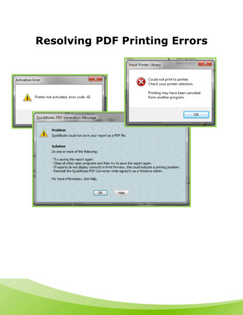
III) Topologya) Operation:All dc-dc converters operate by rapidly turning on and off a MOSFET, generally with ahigh frequency pulse. What the converter does as a result of this is what makes the SEPICconverter superior. For the SEPIC, when the pulse is high/the MOSFET is on, inductor 1 ischarged by the input voltage and inductor 2 is charged by capacitor 1. The diode is off and theoutput is maintained by capacitor 2. When the pulse is low/the MOSFET is off, the inductorsoutput through the diode to the load and the capacitors are charged. The greater the percentage oftime (duty cycle) the pulse is low, the greater the output will be. This is because the longer theinductors charge, the greater their voltage will be. However, if the pulse lasts too long, thecapacitors will not be able to charge and the converter will fail as shown in Fig 3.6.Fig 3.1 SEPIC operation [4]4
Fig 3.2 SEPIC SimulationFig 3.3 Graph of Vout and PulseThis graph shows the output ripple as a function of the input square wave.Fig 3.4 Graph of ICout, IL1 and PulseThis graph shows the ripple in the inductors and how the output capacitor charges and dischargesbased on the pulse.5
b) Specifications:The converter should meet certain standards6V Vin 18VVout 10VIout 1AFsw 50 kHzAn acceptable output current ripple is io, pp 0.5 AAn acceptable output voltage ripple is Vo, pp 0.1 Vc) Duty Cycle Calculation:The amount that the SEPIC converters step up or down the voltage depends primarily on theDuty Cycle and the parasitic elements in the circuit.The output of an ideal SEPIC converter isD * ViVo 1 DHowever, this does not account for losses due to parasitic elements such as the diode drop VD.These make the equation:D * Vi1 DThis becomesVo VDD Vi Vo VDVo VD The maximum Duty Cycle will occur when the input voltage is at the minimum. If VD .5V, theDuty Cycle is10V .5V .646V 10V .5VThe minimum Duty cycle will occur when the input voltage is at the maximum.D min D min 10V .5V .3718V 10V .5V6
d) Inductor Calculation:In theory, the larger the inductors are the better the circuit will operate and reduce theripple. However, larger inductors are more expensive and have a larger internal resistance. Thisgreater internal resistance will make the converter less efficient. Creating the best converterrequires choosing inductors that are just large enough to keep the voltage and current ripple at anacceptable amount.L Vi min ( D max)(6V )(.63) 151.2uH io max f sw(.5 A)(50kHz)Inductors with low internal resistance and around 150uH will be ideal for both of the inductors inthe circuit.e) Simulation Results:SEPIC WITH PARASITICSV1010RL1 11.5.07L11.52150u IC 0S20200SWK.MODELSWK VSWITCH (RON .2 ROFF 1MEG VON 1VOFF 0)VP200PULSE (01001n1n.01045m.02m)RCl 22.5.08C12.5310uIC 0L233.5150u IC 0RL2 3.50.07D34Dix.MODELDixD (RS .07 BV 480N .01)C244.5100u IC 0RC2 4.50.08R4010.PROBE.TRAN.005 .1.099 10uUIC.END7
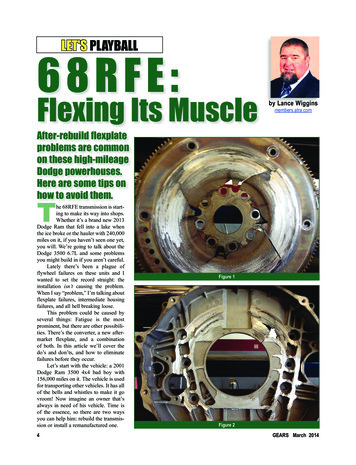
Fig 3.5 Graph of VoutFig 3.6 Graph of Pout and PinThis graph shows that the efficiency of the Converter Pin/Pout .918
SEPIC AVERAGED MODEL WITH PARASITICS AND D INCREASING FROM 0 TO 1VC300PWL (0, 0 100m, 1)D increasing from 0 to 1V1010L111.5150u IC 0RL1 12.3VD230E320Value {(1-V(30))/V(30)*V(5)}MOSFET V Vo*(1-D)/DVF2000C133.51uIC 0RC1 3.54.08L244.5150u IC 0RL2 4.50.3G45Value {((1-V(30))/(V(30)*V(30)))*I(VF)} Diode I Iin*(1-D)/D2C255.5100u IC 0RC2 5.50.08R5010.PROBE.TRAN0.1010uUIC.ENDFig 3.7 Graph of Vout, D and VCin with Vin 10VThis graph shows that as D increases from 0 to 1, Vout increases exponentially, reaching Vinaround D .5. When D gets too high, VCin cannot stay charged and this causes Vout to drop aswell.9
IV) Potentiometer Controlled PWMThe SEPIC converter is able to either increase or decrease an input voltage by controllingthe Duty Cycle of a pulse to the MOSFET. One way to do that is to directly control the Dutycycle using a potentiometer. There are some applications for which this control method issuitable but it is insufficient for many other applications.In order to drive the MOSFET, a pulse is needed. A 555 timer is used to produce a squarewave with a set frequency and a Duty cycle 50%. However, the duty cycle from the 555 cannotbe easily changed without switching resistors. In addition, the SEPIC requires a duty cycle below50% to buck the voltage when the input voltage is low. The pulse width will need to be modifiedseparately from the 555 because the 555 cannot change or produce a duty cycle less than 50%.First a resistor and a capacitor are used in lowpass to produce a triangle wave from the squarewave output of the 555. Afterwards, this is sent to the negative pin of a comparator. The positivepin of the comparator receives a controlled voltage signal. Whenever the controlled voltage isgreater than the triangle wave, the comparator will output voltage and otherwise it will be off.The greater this signal, the greater the duty cycle of the comparator output will be. One way tocontrol this signal is to step down voltage using a potentiometer. Luckily, this signal can be keptin the same range as the triangle wave by using the same input that drives the 555 timer. Theduty cycle will not change when the input or the output voltage changes which means there isfull control of how much the SEPIC steps up or down the voltage. This has both advantages anddisadvantages for the circuit.Full control of the circuit can be useful. The potentiometer allows the SEPIC to output awide range of voltage from a wide range of input. This could be useful in battery applications10
that need to run on various levels of power. One example would be a flashlight with adjustablebrightness. This SEPIC converter could allow it to run on a large range of power with greaterefficiency than simply reducing the voltage with a potentiometer to control the output. However,this control method does have its drawbacks.Most applications of the SEPIC converter control the voltage automatically. The problemwith relying on controlling the input for circuit control is that there is no circuit feedback. Whenusing a potentiometer, the only way to maintain the correct output is to watch the output andadjust accordingly. Visual feedback is only useful in certain circumstances. Usually it is best touse the SEPIC converter to hold a single output without the need for control when using a SEPICas part of a large circuit.11
a) PWM DemonstrationFig 4.1 Graph of Triangle wave and Sinusoidal control waveFig 4.2 Graph of controlled square waveThis graph shows the resulting output of the comparator with the inputs shown in Fig 4.1. Thepulse is high when the control signal is greater than the triangle wave. This results in a higherduty for high control signals.12
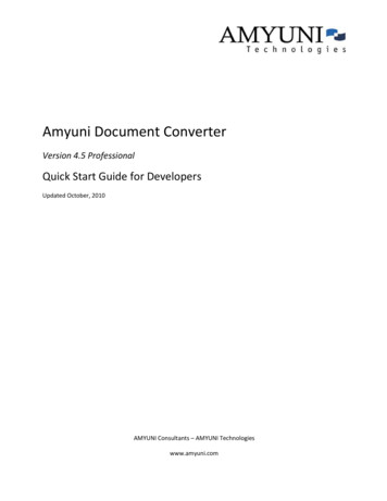
b) Circuit DiagramFig 4.3 Labelled schematic of SEPIC converter using a potentiometer to control PWM.c) Simulation ResultsFig 4.4 Graph of 555 and Triangle waveThis is the output of the 555 with the triangle wave produced by the capacitor in lowpass.13
Fig 4.5 Graph of Comparator output to MOSFET, Triangle Wave and Control Signal from PotentiometerThis graph shows that the comparator turns on soon after the triangle wave falls below thecontrol signal (which is a simulation error) and turns off immediately when the triangle waverises above the signal.14
V) Feedback Controlled PWMWhile a potentiometer allows for control of the SEPIC converter output during operation,it is unable to hold a constant output with a variable input that changes. This is used in themajority of SEPIC converter applications which require automation to correct an input voltage.The simplest way to maintain a constant output is to use a feedback loop that will change theoutput automatically instead of by manual control (using visual feedback from a voltmeter). Thefeedback loop should be able to increase the duty cycle to raise the output when the output is toolow and decrease it when the output is too high. To do this, the output will need to be comparedto a reference voltage which remains constant even if the input changes. The error between theoutput and the reference voltage is then amplified and added to a set bias voltage. The resultingvoltage is then used as the control voltage for PWM. When the output is too low, the amplifiederror increases which causes the control voltage to increase. The increase in control voltageincreases the duty cycle until the output is correct. When the output is too high, the amplifiederror becomes negative which decreases the duty cycle to correct output. Both of these scenarioswork together to constantly make slight adjustments to the duty cycle so that the output remainsstable. The simulations for feedback show how the output changes with the gain of the amplifier15
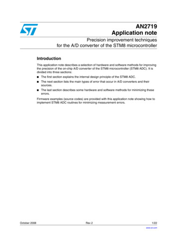
a) Feedback Flow ChartFig 5.1 Flow chart for feedback operationb) Feedback Results at Various Levels of GainSEPIC AVERAGED MODEL WITH FEEDBACKGainFeedback loopVe30010Ee330Value {(1 7*(V(30,0)-V(5,0)))}Eb340Value {.5*(1 (V(30,0) V(33,0))/10)}SEPIC averaged modelV.500VC1.5PWL(0,0 100m, 20)L111.5150u IC 0RL1 12.07VD230E320Value {(V(34,0)-1)/V(34,0)*V(5,0)}VF2000C133.51uIC 0RC1 3.54.08L244.5150u IC 0RL2 4.50.07G45Value {(V(34,0)-1)/(V(34,0)*V(34,0))C255.5100u IC 0RC2 5.50.08R5010.PROBE16Gain*(Vref-Vo) Gain*Errorthis value equals D
.TRAN.END0.1010mUICFig 5.2 Graph of Vout, as Vin increases. Gain is almost zeroThis graph shows that if the gain of the amplifier is around zero, Vout is uncontrolled.Fig 5.3 Graph of Vout, as Vin increases. Gain is too lowThis graph shows that if the gain of the amplifier is too low, Vout is controlled, but too high.17
Vin 6V MinimumFig 5.4 Graph of Vout, as Vin increases. Gain is too highThis graph shows that if the gain of the amplifier is too high, the converter cannot boostsufficiently and Vout does not reach 10V until after Vin is greater than the minimum value.Vin 6V MinimumFig 5.5 Graph of Vout, as Vin increases. Gain is at a good valueThis graph shows that with the correct amount of gain, Vout will be at the correct value as longas Vin is greater than the minimum value.18
VI) SummaryMost battery operated circuits require dc-dc conversion to maintain full operation. Inmost circumstances that require stepping up and down the input voltage, SEPIC converters areworth the price of the extra inductor and capacitor for the efficiency and stable operation theyprovide. While this project does go into detail about simulation results for the SEPIC converter,the physical potentiometer controlled SEPIC converter built was unsuccessful. Additionally, acost benefit analysis to determine peak efficiency with the cheapest cost for the inductors andcapacitors was never done. These are both things that could have been done with extra time andgroup members. From this project, one learns dc-dc converter optimization and control.19
VII) References1. Falin, Jeff. “Designing DC/DC converters based on SEPIC topology” 2008, TexasInstruments. December 2013 http://www.ti.com/lit/an/snva168e/snva168e.pdf 2. Dr. Ridly, Ray. “Analyzing the Sepic Converter” 2006, Ridley Engineering. March 2014 pic%20Analysis.pdf 3. Durán, E. Sidrach-de-Cardona, M. Galán, J. Andújar, J.M. “Comparative Analysis of BuckBoost Converters used to obtain I-V Characteristic Curves of Photovoltaic Modules” April 2014 r 04592243 Pictures from[4] Wikipedia user Mclausma http://en.wikipedia.org/wiki/File:S1 open.jpg http://en.wikipedia.org/wiki/File:S1 closed.jpg 20
May 01, 2014 · transformer; however dc-dc conversion is not as simple. Diodes and voltage bridges are useful for reducing voltage by a set amount, but can be inefficient. Voltage regulators can be used to provide a reference voltage. Additionally, battery voltage decreases as batteries discharge whic